

Triangle Engineering CC3623, CC3022, CC3023, CC3622, CC4223 Installation And Operation Manual
...Page 1

OWNER’S
MANUAL
Keep for
COMFORT COOLER
Whole House Fans
future reference
READ AND SAVE THESE INSTRUCTIONS!
INSTALLATION AND OPERATION
®
IMPORTANT: Carefully read these instructions
before you install or operate your new whole house
fan. Proper installation is important to achieve
maximum cooling efficiency. It is necessary to provide adequate ventilation to meet minimum exhaust
CAUTION - SAFETY RULES
WARNING - TO REDUCE THE RISK OF FIRE,
ELECTRIC SHOCK, OR INJURY TO PERSONS,
OBSERVE THE FOLLOWING:
Use this unit only in the manner intended by the
manufacturer. If you have questions, contact the
manufacturer.
Before servicing or cleaning unit, switch power
off at service panel and lock service disconnecting
means to prevent power from being switched on
accidentally. When the service disconnecting means
cannot be locked, securely fasten a prominent warning
device, such as a tag, to the service panel.
Installation Work And Electrical Wiring Must Be
Done By Qualified Person(s) In Accordance With All
Applicable Codes And Standards, Including Fire-rated
Construction.
Sufficient air is needed for proper combustion and
exhausting of gases through the flue (chimney) of fuel
burning equipment to prevent back drafting. Follow
the heating equipment manufacturer’s guideline and
safety standards such as those published by the
National Fire Protection Association (NFPA), and the
American Society for Heating, Refrigeration and Air
requirements. This prevents pressure build-up in
the attic which will reduce the fan's efficiency. Refer
to the ventilation work sheet on the back page of
this instruction sheet to determine the exhaust air
requirements.
Conditioning Engineers (ASHRAE), and local code
authorities.
When cutting or drilling into wall or ceiling, DO NOT
damage electrical wiring and other hidden utilities.
CAUTION - For General Ventilating Only, Do Not
Use To Exhaust Hazardous Or Explosive Materials
And Vapors.
CAUTION - This Unit Has An Unguarded Impeller.
Do Not Use In Locations Readily Accessible To
People Or Animals.
Your whole house fan will operate only on 120 Volt,
A.C., 60 Hz (cycle) current.
Permanent THREE WIRE (grounded) wiring must
be used. DO NOT USE AN EXTENSION CORD.
To avoid risk of electrical shock, fire and other
injuries DISCONNECT MAIN POWER SUPPLY prior
to installation.
This fan is to be mounted in a location where the
entrance of drawn in water (rain) is unlikely.
If shutter is removed for servicing, replace before
normal operation.
WARNING: TO REDUCE THE RISK OF FIRE OR
ELECTRICAL SHOCK, DO NOT USE THIS FAN WITH
ANY SOLID-STATE FAN SPEED CONTROL DEVICE.
Do not operate this fan in areas where gas or oil
fired equipment are in operation.
Wear safety goggles when drilling, hammering or
cutting materials.
TRIANgLE ENgINEERINg Of ARkANSAS, INc.
E-mail: mail@trianglefans.com • Website: www.trianglefans.com
TM
1101 North Redmond Road • Jacksonville, Arkansas 72076 • (501) 982-7558 • Fax (501) 982-5691 • 1-800-255-9014
LIMITED
10 YEAR
WARRANTY
INSTALLATION RECORD Please complete for future use.
Model # ____________________________________________
Serial # ____________________________________________
Purchased from ______________________________________
Date Purchased ____________ Date installed ______________
Page 1
Revised 5/12
Page 2

Tools required for installation
• Hammer
• Utility Knife or sheetrock saw
• Power or handsaw
• Pencil
• Framing square
• Straight edge
• Measuring tape
• Screwdriver
• Safety goggles
• Power or hand drill
Other materials required
• Framing lumber
• Platform lumber
• Automatic ceiling shutter
• Code required electrical materials
A
(square)
C
B
VERTICAL INSTALLATION:
Contact the factory
for information and
instructions on vertical
installation of the
Comfort Cooler Fan.
C.F.M. Blade Weight Dimensions Cools
Model H.P. Hi-Lo Dia. LBS. A B C Sq. Ft.
CC 2422 1/3 5,600 / 3,700 24" 57 30" 4" 15" up to 800
CC 3022 1/3 7,600 / 5,100 30" 62 34" 4" 15" 800 - 1,200
CC 3023 1/2 8,400 / 5,600 30" 67 34" 4" 15" 900 - 1,500
CC 3622 1/3 9,700 / 6,400 36" 77 40" 4" 15" 1,200 - 1,800
CC 3623 1/2 10,600 / 7,100 36" 82 40" 4" 15" 1,500 - 2,500
CC 4223 1/2 12,600 / 8,400 42" 91 46" 4" 15" 2,200 - 3,200
CC 4823 1/2 14,500 / 9,700 48" 107 52" 4" 15" 2,500 - 4,000
SPECIFICATIONS - FANS
STOP!
SHUTTER INSTALLATION NOTICE!!!
If you have purchased this fan with a Model “CSS”
shutter, read the section for “CSS” shutter installation
only. (See pages 4,5).
If you have purchased this fan with a Model
“AS” shutter, read the section for “AS” Shutter
installation only. (Pages 2,3).
LOCATION OF FAN: The most logical place to
locate your whole house fan is near the central part
of the house. Check attic area to be certain there
is a clearance space above the fan equal to the
diameter of the fan blade. Inspect the area where
the fan is to be installed. The area must be free of
electrical wiring and pipes.
CAUTION: DO NOT OPERATE THIS FAN UNTIL
SHUTTER IS INSTALLED!
“AS” SERIES SHUTTER INSTALLATION
“AS” SHUTTERS
Fan Outside Inside
Model Size Dimension Dimension
AS10 24" 26" x 26" 24" x 24"
AS11 30" 32" x 32" 30" x 30"
AS13 30" 32" x 38" 30" x 36"
AS14 30" 34" x 36" 32" x 34"
AS15 36" 35" x 38" 33" x 36"
AS16 36" 34" x 45" 32" x 43"
AS18 42" 36" x 48" 34" x 46"
AS26 48" 38" x 58" 36" x 56"
STEP 1. After the installation site has been
selected, clear the area of all insulation.
Establish the location of the shutter on the finished
side of the ceiling. Use the INSIDE DIMENSIONS of
the shutter and draw the four corners of the opening.
Drill a
1
/4" hole at each corner. Return to the attic
and inspect the area to make certain that the fan
and shutter installation area will not be obstructed
and that area is conveniently located for ease of
THE SAME SIZE
inside dimensions
as shown in this
CAUTION:
DO NOT CUT
THE SHUTTER
OPENING
AS THE FAN
OPENING.
Use the shutter
chart.
installation. Use a utility knife or sheetrock saw and
carefully cut the shutter opening. (See fig. 1).
STEP 2. From the attic side cut the ceiling joist 1
back from shutter opening. This is to accommodate
additional framing to support the joists that have
been cut. (See fig. 1).
STEP 3. Frame the opening using lumber EQUAL
TO THE EXISTING JOISTS. Attach the new framing to
the existing joists. Before fastening, make sure that
the existing joists that were cut DO NOT sag below
the uncut joists and new framing. (See fig. 2).
STEP 4. If additional framing or blocking is needed to
support the shutter, install it at this time. (See fig. 4).
STEP 5. Remove the two (2) screws that secure
the fan to the plenum. Pass the fan and plenum into
the attic through the framed opening in the ceiling
and set them aside at this time.
STEP 6. Build a platform to support the fan using
lumber, plywood or other material a minimum of
3
/4" thick. The platform must be constructed so that
it supports all four sides of the fan, and should be
wide enough to prevent Attic Air from being drawn
Page 2
1
/2"
Page 3
“AS” SERIES SHUTTER INSTALLATION, continued
into the fan. With some combinations of fan and
shutter, a portion of the opening may be blocked
by the platform. This will not effect the efficiency of
the fan. Fasten the platform to the joists and new
framing. (See fig. 2).
STEP 7. Center the plenum on the platform and
toe nail it in place. NOTE: WHEN TOE NAILING
PLENUM TO PLATFORM MAKE CERTAIN THAT THE
SIDES OF THE PLENUM REMAIN STRAIGHT AND
SQUARE OR THE FAN WILL NOT FIT PROPERLY.
STEP 8. To prevent Attic Air from entering the
plenum, tape all of the joints of the new framing,
platform and plenum with duct tape or aluminum
foil tape.
STEP 9. Place the fan on the plenum making sure
that the rubber isolation mount is in place between
the fan and plenum. DO NOT REPLACE SCREWS.
This is to permit the fan to “float” on the rubber
mount which helps reduce noise. (See fig. 4).
STEP 10. Install the flush mounted ceiling shutter
into the ceiling opening using the screws provided.
Caution should be taken not to effect the free
operating action of the shutter. (See figs. 3 & 4).
REFER TO THE “ELECTRICAL WIRING”
SECTION ON PAGES 5 & 6.
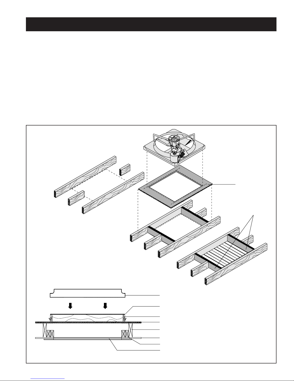
Fig. 1
Fig. 4
Platform
New framing
Fig. 2
Fig. 3
Fan Frame
Rubber Mount
Plenum
Platform
Existing Joist
Ceiling
Blocking as needed
Shutter
Page 3
Page 4

“CSS” SERIES SHUTTER INSTALLATION
Models CSS-24, CSS-30 & CSS-36, install on joists with 16" or 24" centers.
Model CSS-42 installs on 24” centers only.
CAUTION: DO NOT CUT THE SHUTTER OPENING
THE SAME SIZE AS THE FAN OPENING.
Use the shutter inside dimensions as shown in the
shutter specification chart below.
“CSS” SHUTTERS
OPENING SIZES - Installs centered on a joist with 16" or 24" centers.
Cut two openings, one on each side of center joist per shutter model:
Model Fan Size Outside Dimension Opening Size
1
CSS-24 24" 24" x 32" 10
CSS-30 30" 32" x 35" 14
CSS-36 36" 32" x 43" 14
*CSS-42 42" 38" x 49" 17
For 24" o.c. joists only
*
STEP 1. After the installation site has been
selected for the fan, remove any insulation from the
area and select a ceiling joist to be the center line
of the fan.
Use the shutter carton to make a template for the
opening your shutter requires. (See above) FROM
THE ATTIC SIDE OF THE INSTALLATION SITE place
/4" x 301/4"
1
/4" x 341/4"
1
/4" x 411/4"
1
/4" x 463/4"
the template on the ceiling and against the joist that
will be the center of the fan. With a pencil trace
around the template. Repeat this procedure on the
1
exact opposite side of the joist. Drill a
/4" hole at each
corner of the pencil lines. YOU SHOULD HAVE EIGHT
(8) HOLES. From directly below the attic, check to be
sure that the location is correct.
STEP 2. Return to the attic, and using a utility knife
or sheetrock saw carefully cut the shutter opening
following the pattern on both sides of the joist. (See
fig. 5).
DO NOT REMOVE THE SHEETROCK
FROM THE CENTER JOIST.
STEP 3. Frame the opening using lumber EQUAL
TO THE SIZE OF THE EXISTING JOISTS. (See fig. 6).
STEP 4. If the opening is less than the distance
between the joists, fasten supports between the new
framing along the edge of the opening. (See fig. 8.).
STEP 5. Remove the two (2) screws that secure the
fan frame to the plenum. Pass the fan and plenum into
the attic through the framed opening in the ceiling.*
Set them aside at this time.
Fig. 5
*If the fan does not fit through
the framed opening, use your
attic access opening. The current
building code requires this access
opening to be at least 22" x 30".
Platform
New framing
Fig. 6
Fig. 7
Page 4
Page 5

“CSS” SERIES SHUTTER INSTALLATION, continued
STEP 6. Build a platform to support the fan using
lumber, plywood or other suitable material a minimum
3
of
/4" thick. The platform must be constructed so
that it supports all four sides of the fan, and should
be wide enough to prevent Attic Air from being
drawn into the fan. With some combinations of fan
and shutter, a portion of the opening may be blocked
by the platform. This will not effect the efficiency of
the fan. Fasten the platform to the joists and new
framing. (See fig. 6).
STEP 7. Center the plenum on the platform and
toe nail it in place.
Fig. 8
Fan Frame
Rubber Mount
Plenum
Platform
Existing Joist
Ceiling
No Cut Joist Shutter (CSS)
Blocking as needed
NOTE: WHEN TOE NAILING PLENUM TO PLATFORM
MAKE CERTAIN THAT THE SIDES OF THE PLENUM
REMAIN STRAIGHT AND SQUARE OR THE FAN
WILL NOT FIT PROPERLY.
STEP 8. To prevent Attic Air from entering the
plenum, tape all of the joints of the new framing,
platform and plenum with duct tape or aluminum
foil tape.
STEP 9. Place the fan on the plenum making sure
that the rubber isolation mount is in place between
the fan and the plenum. DO NOT REPLACE SCREWS.
This is to permit the fan to “float” on the rubber
mount which helps reduce noise. (See fig. 8).
STEP 10. Install the flush
mounted ceiling shutter into
the ceiling opening using the
screws provided. Caution
should be taken not to effect
the free operating action of
the shutter. (See fig. 8).
REFER TO THE "ELECTRICAL
WIRING" SECTION BELOW.
This fan requires a 120 Volt AC. power source with
at least 15 amp capacity. All electrical wiring must be in
accordance with local electric codes. Use 12 gauge or
larger for all the fan wiring.
STEP 1. Get professional help If you are not familiar
with electrical wiring and local wiring codes.
STEP 2. Turn OFF power at the Fuse/Circuit Breaker
Box before wiring. (See safety rules on pg. 1).
STEP 3. WARNING: TO REDUCE THE RISK OF
ELECTRICAL SHOCK AND DAMAGE TO THE FAN
MOTOR, DO NOT USE THIS UNIT WITH ANY SOLID
STATE OR VARIABLE SPEED CONTROL DEVICE.
STEP 4. For ease of electrical wiring installation it is
recommended that a junction box is mounted in the close
proximity of the fan motor. This should be mounted to a
ceiling joist within a few feet of the fan. REFER TO THE
WIRING DIAGRAMS (figs. 9 & 10) BEFORE STARTING
INSTALLATION.
STEP 5. Select a wall in the structure in a convenient
location and as close to the fan as possible, to mount
the switch that will operate the fan. Once selected, cut a
rectangular hole in the wall to mount a standard electrical
box. This hole should be next to a stud and at the height
of the standard wall switches throughout the structure.
ELECTRICAL WIRING
STEP 6. Once this hole is cut, and before the electrical
box is mounted inside the wall, return to the attic space
and drill at least a 1" diameter hole in the wall top plate
directly above the location where the hole was cut in the
wall.
STEP 7. Feed the electrical wire through the 1" hole in
the top plate until the wire extends down through the wall
to the point it can be brought through the hole in the wall
at the switch location. Working from the switch location,
pull at least 18" of wire through the switch hole.
STEP 8. Feed the wire through the top hole of the
switch box making sure that the wire is anchored to the
box correctly, and insert the box into the rectangular
hole. When the box is installed correctly, the sides of
the box should be flush with the outside surface of the
sheetrock and the box must be secured to the stud.
NOTE: SINCE THERE ARE VARIOUS TYPES OF
ELECTRICAL BOXES THAT CAN BE USED,
CONSULT YOUR LOCAL ELECTRICAL SUPPLIER
STEP 9. Return to the location of the junction box
and insert the opposite end of the wire from the switch
through one of the holes in the side of this box. After the
wire is inserted and anchored properly, the wire may be
Page 5
FOR HIS SUGGESTIONS.
(continued)
Page 6

ELECTRICAL WIRING, continued
cut off leaving approximately 12" inside the junction
box. (See fig. 10).
STEP 10. Go to the fan motor and connect the wires
as shown in appropriate wiring diagram. (See fig. 9).
Route the wire from the motor through the junction
box, anchor securely, and cut leaving approximately
12" in the box. (See fig. 10).
STEP 11. For the power source, it will be necessary
to route from the fuse/circuit breaker box to the
junction box in the attic space. To accomplish this, it
will be necessary to add a circuit breaker. An alternate
method is to use an existing electrical source already
in the attic space. With either method, route this wire
to another hole in the junction box and cut off leaving
approximately 12" of wire in the box. YOU SHOULD
NOW HAVE THREE SEPARATE LINES (WIRES) IN THE
JUNCTION B0X, ONE FROM THE SWITCH LOCATION,
ONE FROM THE FAN MOTOR AND ONE FROM THE
POWER SOURCE.
STEP 12. Using wire nuts connect all wires as
shown in the wiring diagram. It will be necessary to cut
off some of the excess wire in the switch and junction
boxes since these wires must be placed inside these
boxes with the covers anchored securely in place.
When the switch is installed in the switch box BE SURE
THAT THE WALL SWITCH IS IN THE OFF POSITION.
Fig. 9
Fig. 10
STEP 13. Return to the attic. MAKE CERTAIN THAT
THE FAN BLADES ARE CLEAR AND THAT NO WIRES
OR OTHER OBSTRUCTIONS ARE NEAR THE BLADES.
STEP 14. Verify all electrical connections. Switch
power ON at the Fuse/Circuit Breaker Box.
NOTE: WINDOWS IN AT LEAST ONE ROOM OF
STRUCTURE MUST BE OPEN BEFORE TESTING THE
FAN.
STEP 15. TESTING THE FAN. (See fig. 9). Turn
the switch on to High, allow the fan to run for several
seconds, then turn the switch to Low.
STEM 16. With the fan operating, return to the attic
and observe the fan. If the V-Belt is vibrating, turn
OFF the fan, and switch the power at the Fuse/Circuit
Box to the OFF position. See the SAFETY RULES on
page 1. Move the fan spring to the end hole of the
motor-mounting plate. (See page 7). After repositioning
the spring, switch the power at the Fuse/Circuit Breaker
Box to the On position. Re-test the fan.
STEP 17. After testing, replace the insulation around
the plenum and new framing.
Junction Box
To 120V
Power Source
Wall Switch
Page 6
Page 7

REPAIR & REPLACEMENT PARTS
Key
No. Description
1 Fan Frame 24" (Venturi)
Fan Frame 30" (Venturi)
Fan Frame 36" (Venturi)
Fan Frame 42" (Venturi)
Fan Frame 48" (Venturi)
1
2 Motor
Motor
/3 HP, 2 Speed
1
/2 HP, 2 speed
3 Blade Assembly 24"
Blade Assembly 30"
Blade Assembly 36"
Blade Assembly 42"
Blade Assembly 48"
5
4 Carriage Bolt
/16" 18x3/4"
5 Nut 5/16" 18 (4 req'd)
6 Fan Spring
7 Wood Frame 24"
Wood Frame 30"
Wood Frame 36"
Wood Frame 42"
Wood Frame 48"
8 V-Belt 24"
V-Belt 30"
V-Belt 36"
V-Belt 42"
V-Belt 48"
9 Motor Pulley 24"
Motor Pulley 30"
Motor Pulley 36"
Motor Pulley 42"
Motor Pulley 48"
10 Fan Pulley 24"
Fan Pulley 30"
Fan Pulley 36"
Fan Pulley 42"
Fan Pulley 48"
11 Fan Shaft
12 Bearing (2 req'd)
†* 2-Speed Wall Switch
†* 12 Hour Timer
(4 req'd)
REPAIR PARTS
When ordering repair parts, always give the
following information:
1. Part description
2. Fan model no.
3. Fan serial no.
10
12
11
8
9
12
6
4
7
NOTICE:
been removed.
TO REPOSITION OR REPLACE SPRING:
A. Remove V-Belt (8).
B. Hook spring (6) as shown.
C. Position V-Belt (8) onto motor pulley (9)
while pulling the V-Belt to position it onto the
fan pulley (10).
SAFETY WARNING: Do not rotate fan by pulling
on V-Belt. Severe injury could result if fingers are
entrapped between the V-Belt and pulley. Read the
safety rules on page 1 of this manual.
5
2
3
Replace spring (6) in area shown if it has
1
SEE
NOTICE
BELOW
ON
SPRIN
G
†* = optional
Page 7
Page 8

VENTILATION REQUIREMENTS
The following work sheet is provided so you may determine the existing ventilation in your attic. It is necessary
that you provide adequate ventilation to meet the minimum
exhaust requirements for the fan you have selected. Should
Turbine Ventilator
(12" throat) 3
A
Roofcap
2
Under Eave Vent
1
A
B
B
Type QTY.A (ft.) B (ft.)
A
xxxx
1
2
3
4
5
OTHER FORMS OF VENTILATION
TOTA L NET FREE EXHAUST AREA
NET VENT
(sq. ft.)
1
.13
you calculations show your exhaust area is inadequate,
additional ventilation must be provided. Failure to meet
minimum exhaust requirements will result in a reduction
of fan efficiency and motor failure.
Roof Ridge
Ventilator
4
LOSS
FACTOR
.5
.6
.6
(sq. ft.)
A
NET FREE
=
AREA (sq. ft.)
B
Louvers
5
(Rectangular &
Triangular)
B
A
Min. Free
Exhaust
Model Area Req’d
CC 2422 8 sq. ft.
CC 3022 10 sq. ft.
CC 3023 11 sq. ft.
CC 3622 12 sq. ft.
CC 3623 16 sq. ft.
CC 4223 18 sq. ft.
CC 4823 22 sq. ft.
LIMITED TEN YEAR WARRANTY
Do not return product to original place of purchase
Triangle Engineering of Arkansas, Inc. (Manufacturer) warrants, from
the date of purchase, to the original purchaser only, that the product
manufactured by Manufacturer is free from defects in material and
workmanship for a period of TEN (10) YEARS. Motors, capacitors,
v-belts and switches are excluded from this warranty, but shall have
a limited one year warranty from date of purchase to the original
purchaser.
If a failure of the product occurs, contact the Manufacturer at: 1-800-
255-9014 and give the model number of the product, the purchase
date, and a description of the problem to the customer service agent.
Once the problem is diagnosed, and proof of purchase date is
verified, Manufacturer will have the option of shipping the necessary
repair part(s) to the Customer, freight prepaid or having the product
returned to Manufacturer for repair or replacement. If the product is
returned to the Manufacturer, Customer is responsible for prepayment
of all inbound freight charges. Upon repair or replacement, which shall
be at the discretion of Manufacturer, the Manufacturer will prepay all
outbound freight charges for the return of the product to the customer.
However, if Manufacturer finds product to be in operating condition
and no problems are diagnosed, product will be returned to customer
freight collect.
THERE ARE NO WARRANTIES WHICH EXTEND BEYOND THE
DESCRIPTION ON THE FACE HEREOF except as provided by this express
warranty, the goods are sold “as is” without any implied warranties.
This limited warranty does not cover labor to replace warrantied parts
or motors, nor does it cover failure of the installer to provide adequate
ventilation to meet minimum exhaust requirements, damage resulting
from accident, misuse or abuse, lack of proper maintenance, improper
installation, affixing of any parts or attachments not authorized by
Manufacturer, or loss of parts.
In no event shall Manufacturer be liable for any special, incidental, or
consequential damages; which may result from any defect in material
or workmanship.
It is expressly understood that Buyer’s sole and exclusive remedy
shall be repair or replacement of defective parts, and that Triangle
Engineering shall not be liable for injury to persons or property. Should
the goods prove so defective, however, as to preclude the remedying
of warranted defects by repair or replacement, the Buyer’s sole and
exclusive remedy shall then be a refund of the purchase price.
This warranty gives you specific legal rights, and you may also have
other rights which vary from state to state.
MOTOR REPLACEMENT DURING WARRANTY PERIOD:
If the motor on your WHOLE HOUSE FAN should fail during the first
year of operation, simply remove the LABEL ONLY from the motor
and mail the original label and copy of purchase receipt to Triangle
Engineering. Once the label is received, and if the motor is still under
warranty, we will ship a new motor within 24 hours, UPS prepaid. DO
NOT RETURN MOTOR.
Page 8
 Loading...