

Trianco EuroTrader 50/90, EuroTrader 100/125, Utility 50-65, Utility 70-90, Utility 100-125 User, Installation, Commissioning & Servicing Instructions
Page 1

To be retained by householder
USER, INSTALLATION
COMMISSIONING & SERVICING
INSTRUCTIONS
EuroTrader 50/90
EuroTrader 100/125
OIL FIRED CENTRAL HEATING BOILERS
FOR BALANCED OR CONVENTIONAL FLUE
TRIANCO
BED 92/42 EEC
EMC 89/336 EEC
Page 2

HEALTH AND SAFETY
INFORMATION FOR THE INSTALLER AND SERVICE ENGINEERS
Under the Consumer Protection Act 1987 and the Health and Safety at Work Act 1974, it is a
requirement to provide information on substances hazardous to health (COSHH Regulations
1988).
The Company takes every reasonable care to ensure that these products are designed and constructed to meet these general safety requirements, when properly used and installed.
To fulfil this requirement products are comprehensively tested and examined before despatch.
This appliance may contain some of the items below
.
When working on the appliance it is the Users/Engineers responsibility to ensure that any necessary personal protective clothing or equipment is worn appropriate to parts that could be considered as being hazardous to health and safety.
INSULATION AND SEALS
Glass Rope, Mineral Wool, Insulation Pads, Ceramic Fibre, Glass Insulation.
May be harmful if inhaled. May be irritating to the skin, eyes, nose or throat. When handling avoid
inhalation and contact with eyes. Use (disposable) gloves, face masks and eye protection.
After handling wash hands and other exposed parts. When disposing, reduce dust with water
spray, ensure parts are securely wrapped.
GLUES, SEALANTS & PAINT
Glues, Sealants and Paints are used in the product and present no known hazards when used in
the manner for which they are intended.
KEROSENE & GAS OIL FUELS (MINERAL OILS)
1. The effect of mineral oils on the skin vary according to the duration of exposure.
2. The lighter fractions also remove the protective grease normally present on the surface of the
skin rendering the skin dry, liable to crack and more prone to damage caused by cuts and
abrasions.
3. Skin rashes (oil acne). Seek immediate medical attention for any rash, wart or sore
developing on any part of the body, particularly the scrotum.
4. Avoid as far as possible any skin contact with mineral oil or with clothing contaminated with
mineral oil.
5. Never breathe any mineral oil vapours. Do not fire the Burner in the open i.e. out of the Boiler
as a misfire will cause unburnt oil vapours.
6. Barrier cream containing lanolin such as Rosalex Antisolv, is highly recommended together
with a strict routine of personal cleaning.
7. Under no circumstances should mineral oils be taken internally.
Page 3

CONTENTS
PAGE
USER INSTRUCTIONS 1/2
After sales service information 3
1. INTRODUCTION 4
2. INSTALLATION 5
Regulations 5
Siting the Boiler 5
Combustion Air 5
Extractor fan 5
Water System 5
Electrical Supply 5
Oil Supply 6
3. FLUE SYSTEM 7
Conventional chimney 7
Balanced flue (Room sealed) optional extra 8
2270 & 2271 Horizontal telescopic BF kit 9/10
Assembly Notes 11
2272 High level adaptor kit 12
Assembly method 13
2272 Universal High Level BF Adaptor Kit 14
2272 Universal High Level BF Adapter Kit 1 5
Assembly method 16
2273 Vertical BF Kit 16
2273 Vertical BF Kit - Exploded View 17
2273 Universal High Level BF Adaptor Kit 17
4. ELECTRICAL 18
5. COMMISSIONING 21
Procedure 21
Handing over 21
6. SERVICING 22
Oil Tanks 22
Line Filters 22
Boiler 22
7. FAULT FINDING 23/24
SPARES 24
Boiler parts 24
Page 4
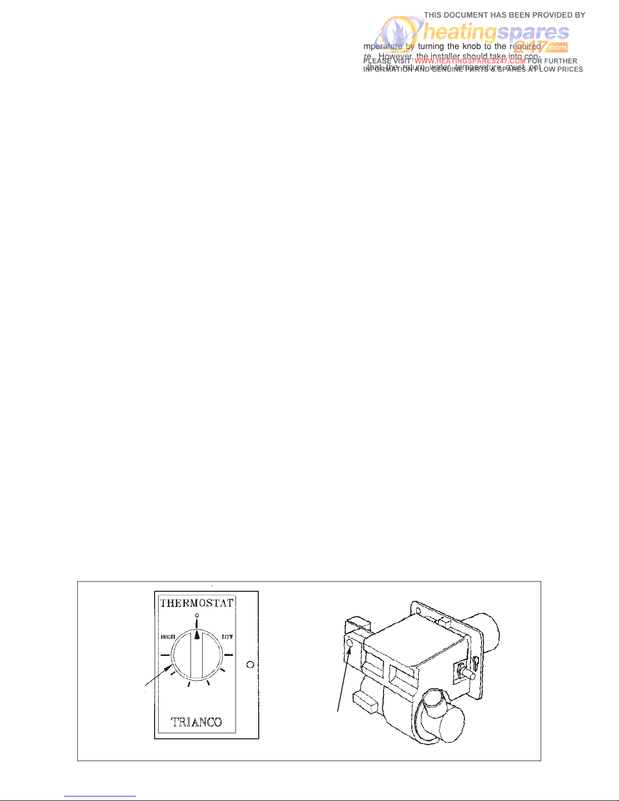
1
BOILER
THERMOSTAT
BURNER LOCK-OUT
LIGHT & RESET BUTTON
PUSH TO RESTART
BURNER
Set the temperature by turning the knob to the required
temperature. However, the installer should take into con-
sideration that the return water temperature must not
drop below 60°C when the appliance is up to full operating
temperature.
The thermostat is switched off when the knob is turned
fully anti-clockwise with pointer opposite ‘O’
BURNER LOCK-OUT
If the burner fails to light, it will go to lock-out. If this
occurs, wait about one minute then remove the front
panel and press illuminated reset button to start burner.
In the event of the burner not firing wait a further minute
and then press the reset button again. If the burner still
fails to start, switch off the electrical supply to the boiler.
WARNING - DO NOT ATTEMPT TO START BURNER
MORE THAN TWICE
(See Simple Fault Finding before contacting your
Service Engineer).
SYSTEMS CONTROLS
ROOM THERMOSTAT
The room thermostat should not be positioned near a
source of heat such as a radiator or exposed to the sun
as this will cause the central heating to switch off before
the room is up to temperature. Follow the manufacturer’s
instructions for best siting position for the thermostat.
TIME-SWITCH/PROGRAMMER
When choosing the operating times for your boiler, it is
useful to remember that central heating usually takes
between half an hour to an hour before it becomes
effective.
It is suggested that the Time-Switch/Programmer is set to
bring on the heating about an hour before heating is
required.
1. Users Instructions
HOW TO USE YOUR TRIANCO BOILER
The Trianco EuroTrader B/H has been designed and
constructed to give years of trouble free service and
these instructions are provided to assist you in obtaining
the best performance with the least trouble and cost.
The boiler is fully automatic in operation and requires
little attention other than the setting of the thermostat and
any system controls such as a room thermostat and
time-switch.
TO FIRE THE BOILER
Before firing the boiler, ensure the system is full of water,
there is sufficient oil in the storage tank and all valves are
open.
1. Check that the Time-switch/Programmer (if fitted) is
ON and the room thermostat is calling for heat.
2. Set the boiler thermostat to the desired temperature.
3. Switch on the electrical supply to the boiler and the
burner should fire after a few seconds of fan
pre-purge.
4. Set the Time-switch/Programmer (if fitted) to the
times and programme required.
5. The boiler will now operate automatically, cutting in
and out according to the heat demand.
TO STOP THE BURNER
The burner may be stopped by turning the Boiler Control
Thermostat fully anti-clockwise to the OFF position ‘O’
If the boiler is to be off for a long time, it is recommended
that the mains supply to the boiler is switched off or the
Time-switch/Programmer (if fitted) is switched to the OFF
position.
BOILER CONTROL THERMOSTAT
The boiler control thermostat enables you to select the
temperature of the water leaving the boiler. It is
calibrated between High and Low in five intermediate
setting, corresponding to a temperature range of 82° C
(high) to 55° C (low).
Page 5
2
Boiler Model
Serial Number
Fuel Type
Oil Tank Capacity
Oil Supplier 1
Oil Supplier 2
It is also worth noting that the heating system will
usually remain effective for up to half an hour after
boiler shut down. The timer can therefore be switched
off earlier as an economy measure.
FROST PROTECTION
If the boiler and central heating is shut down for many
hours during very cold weather, the water may be in
danger of freezing and, as such, it is advisable to protect
the installation with a frost thermostat.
Where the system is not protected, the boiler should be
left switched on and the room thermostat set to a low
setting e.g. 7° C (45° F) to prevent the building temperature falling too low.
If the system is shut down for a long period during very
cold weather, it is advisable to completely drain the
system. However, frequent draining should be avoided,
especially in hard water areas, as this could lead scaling
of the boiler waterways.
SHUTTING DOWN FOR THE SUMMER
If the boiler is shut down for the summer months, it is
advisable to have it serviced and thoroughly cleaned as
soon as possible to minimise corrosion of the heating
surfaces.
OIL
The recommended oil for your boiler is 28 sec.Kerosene
(BS 2869:1983 Class C2).
OIL TANK
Always ensure the tank is topped up at regular intervals,
do not wait until the tank is nearly empty before refilling,
otherwise sludge and water could be sucked into the oil
pipe to affect the burner’s operation and reduce pump
life.
After a delivery of oil, it is recommended that the oil is
allowed to settle in the tank for about half an hour before
restarting the burner.
Sludge and water caused by condensation should be
drawn off at the tank drain-cock annually.
SIMPLE FAULT FINDING
If the burner fails to start for no apparent reason, make
the following checks before calling your Service
Engineer.
1. Check for failure in the electrical supply e.g. a power
cut
2. Check for a blown fuse. If the fuse has blown and on
replacement blows again, switch off the mains
electrical supply to the boiler and call your Service
Engineer.
3. Check that there is adequate oil in the tank and the
shut-off valves are open.
4. Check for burner lock-out. Press the reset button
and burner should fire. DO NOT PRESS MORE
THAN TWICE. Refer to ‘Burner lock-out’ for further
advice.
Note: If the boiler has been off as a result of a power
failure, it will be necessary to reset the
Time
Switch/Programmer to the correct time unless it
has a built-in power reserve.
SERVICING
To ensure efficient and reliable operation of the boiler, it
is essential that the oil burner is initially commissioned by
an OFTEC trained and registered engineer and an annual
service is given thereafter.
Notes:
ELECTRICAL
SAFETY CHECKS SHOULD BE CARRIED
OUT BY A QUALIFIED ELECTRICAL ENGINEER
a It is the responsibility of the installer to ensure proper
commissioning is carried out.
b
It is a requirement of the boiler’s guarantee and any
extended warranty that an annual service is carried
out by a qualified engineer.
Commissioning Engineer
Signature ..........................................................................
Company Name ...............................................................
..........................................................................................
Address ............................................................................
..........................................................................................
..........................................................................................
..........................................................................................
Tel. No: .............................................................................
Page 6

3
TRIANCO
CUSTOMER AFTER SALES SERVICE INFORMATION
SERVICE CENTRE AND TECHNICAL SUPPORT
Tel: 0114 257 2300 Fax: 0114 257 2338
Hours of business Monday to Thursday 8.30am - 4.45pm
Friday 8.30am - 2.30pm
A step by step guide to reporting a fault
with your appliance
A qualified field SERVICE ENGINEER is available to
attend a breakdown or manufacturing fault occurring
whilst the appliance is under guarantee.
The appliance must be made available for service during
normal working hours, Monday to Friday (no weekend
work is accepted).
A charge will be made where:
•
Our Field Service Engineer finds no fault with the
appliance
or
•
The cause of a breakdown is due to other parts of the
plumbing/heating system (including oil line/lack of
oil), or with equipment not supplied by Trianco.
or
•
Where the appliance falls outside the guarantee
period (see terms and conditions enclosed).
or
•
The appliance has not been correctly installed,
commissioned or serviced as recommended (see
commissioning, installation and servicing
instructions)
or
•
The breakdown occurs immediately following an
annual service visit. In this instance your appointed
Service Agent must check all his work PRIOR to
requesting Trianco to attend.
NOTE: Burner nozzles are currently guaranteed
until the first service.
Over 50% of all service calls made are
found to have no appliance fault.
What to do in the event of an appliance
fault or breakdown:
Step 1: Always contact your installer or commissioning
engineer in the first instance, who must
thoroughly check all his work PRIOR to
requesting a service visit from Trianco.
Step 2: If your appliance has developed an in-guarantee
fault your installer should contact
Trianco
Service Centre for assistance.
What happens if my installer/engineer is
unavailable?
Step 3: Contact Trianco Direct. We will provide
you with the name and telephone number of our
Service Agent. However, a charge may apply if
the fault is not covered by the appliance
guarantee (payment will be requested on site by
our independent Service Agent).
PLEASE NOTE:
Unauthorised invoices for attendance and repair work
carried out on this appliance by any third party will not be
accepted by Trianco.
Page 7

4
Please note: It is essential in the interest of boiler effi-
ciency and reliable performance that once the boiler has
been installed it is first commissioned, preferably by an
OFTEC registered engineer.
It is the responsibility of the installer to ensure that the
boiler is commissioned.
Always switch off the electrical supply before removing
any of the covers for cleaning.
If any part of the boiler or its flue is modified, then the
guarantee/warranty will be invalidated.
We recommend that you keep these instructions in a
place near your appliance for easy reference.
Balanced Flue Kits
The boilers are supplied suitably equipped for connection
to a conventional chimney, but can readily be converted
into a room-sealed balanced flue appliance by using a
Trianco balanced flue kit. These kits allow the boiler to be
installed in a wide variety of site conditions, from low-level
discharge through the wall, to high-level discharge (see
balanced flue kit details - section 3 ).
Two distinct styles of flue kit are available. The circular
balanced flue kit is available in both low-level horizontal
and vertical set-ups. The square balanced flue kit is
available in a low-level horizontal format and a high-level
horizontal format (in conjunction with a circular vertical
adaptor kit).
Note:
Both the square and circular low level horizontal
balanced flue kits can be used for left-hand, righthand, and rear exhaust.
1. INTRODUCTION
The Trianco Eurotrader Boiler has been designed to
conform to European Directive/Standards BED 92/42
EEC LVD EN 60335-1 EMC 89/336/EEC.
The matched pressure jet burner which is exceptionally
quiet in operation, ensures clean and efficient
combustion with low NOxemissions
The Eurotrader boiler is suitable for installation in a
garage.
The Eurotrader boilers are suitable for all normal open
vented central heating and indirect hot water systems
and can also be used with sealed systems up to a
working pressure of 3 bar with the appropriate sealed
system safety equipment.
Two flow and return sockets are provided to facilitate
connection to the heating and hot water systems.
Due to high efficiency of this range of boilers; it is recommended that they are filled on fully pumped system using
diagonally opposite connections of the heat exchanger
The boiler is fully automatic in operation and incorporate
all necessary safety controls to ensure safe and reliable
operation.
Trianco EuroStar boilers are supplied with the burner set
for Kerosene 28 sec. Class C fuel to meet the Building
Regulation requirements for low level flue discharge. It is
recommended this fuel is also used when the boiler is
connected to a conventional chimney because of the
clean burning characteristics of Kerosene.
Important Notice:
To comply with regulations in force, your new boiler must be installed and commissioned
by an OFTEC-registered engineer. The installation must also comply with current
Building Regulations, Part L.
Failure to meet the terms of these requirements may invalidate your guarantee.
THE PERSON(S) WHO INSTALLS THIS
APPLIANCE, COMMISSIONS, SERVICES OR
CARRIES OUT ANY REMEDIAL WORK, IE ELECTRICAL FAULT FINDING, MUST
HAVE SUITABLE ENGINEERING QUALIFICATIONS
Page 8

Combustion Air
British Standard Code of Practice for Oil Firing BS 5410:
Part 1 requires a permanent air inlet opening of 550mm
2
per kW of boiler rated output. (over 5kW) The provision of
an adequate supply of combustion air is essential for the
efficient and safe operation of the boiler. The air opening
should be positioned so as to cause the least possible
draught to the occupants and located so it is not liable to
be accidentally blocked.
Ventilation (Conventional Flue Boilers)
Where the boiler is installed in a compartment or a confined space, ventilation openings are also required to pre-
vent overheating of the appliance controls.
Extractor Fan
If the boiler room has an extractor fan, the combustion
performance of the appliance must not be affected when
the fan is running and all doors and windows are closed.
A flue gas check on the CO
2
% and smoke number should
be carried out to prove that combustion is satisfactory.
Water System
The installation must comply with the requirements of the
following Codes of Practice:
BS 5449: Part 1 - Forced Circulation Hot Water Systems.
BS 7074: Part 1 - Code of Practice for Sealed Water
Systems.
Electrical Supply
230V 1 Phase 50Hz (Fused 5 Amp)
Note: THIS APPLIANCE MUST BE EARTHED
All electrical wiring must be carried out by a qualified
electrician in accordance with current I.E.E. Regulations
and any Local Regulations that may apply.
The mains electrical supply can be taken from a double
pole switch (fused 5 amp) situated near the boiler
. The
cable should be heat resisting and routed either along the
top side of the casing in the cable clip provided or run
from the bottom side through the hole in the base tray. It
should be secured with the strain bush in the bottom of
the control panel.
Terminal connections are also provided in the control
panel for ancillary controls.
See wiring diagram Fig. 11
Warning - High and Low Voltage
In certain parts of the country, where there is a known risk
of high or low voltage fluctuations, the oil burner shall be
prevented from starting by the use of a voltage sensitive
device if the voltage drops or increases suf
ficiently to
endanger the installation.
5
Model Minimum FREE Area opening ‘A’
50 105cm
2
(16in2)
90 145cm2(22in2)
100/125 202cm2(31in2)
2. INSTALLATION
Regulations
Installation of the boiler must comply with the following
British Standards and Regulations:
BS 5410: Part 1 - Code of Practice for Oil Firing.
BS 5449 - Forced Circulation Hot Water Central Heating
Systems.
The Building Regulations - Part ‘J’ (England and Wales)
Part ‘F’ Section 111(Scotland)
Part ‘L’
The Control of Pollution (Oil) Regulations
Current I.E.E. Regulations
Local Water Undertakings By-laws
OFTEC Installation Requirements for Oil Fired Boilers
and Oil Storage Tanks.
Health And Safety At Work Act
The installer should be aware of his responsibilities under
the Act and provide, where necessary, appropriate
protection for persons carrying out the installation.
In the interest of safety, the boiler should be installed and
commissioned by an OFTEC trained and registered
engineer.
A useful guide to Safe Working Practices for Oil Firing
Technicians is published by OFTEC.
ELECTRICAL WORK SHOULD BE CARRIED OUT BY
A QUALIFIED ELECTRICAL ENGINEER
Siting the Boiler
Sound Levels
Whilst the low sound level of the Trianco EuroStar boiler
makes it eminently suitable for utility room installation,
the following aspects should be considered before
installation:
(a)
Some people are particularly sensitive to even low
noise levels so this aspect should be discussed with
the householder.
(b) Small rooms tend to amplify noise, particularly if the
wall construction is hollow or the surface tiled.
(c) A chimney passing through a bedroom can some
times transmit noise.
(d) Low level flue terminals produce some exhaust
noise, so care should be taken when siting adjacent
to neighbouring property, patios and play areas.
Clearance and Service Access
When siting the boiler, ensure adequate clearance is
allowed for making water and flue connections and a
headroom of 450mm (18'') is provided for removal of flue
baffles and flu-way cleaning.
A clearance of 750mm (30'')
is also required at the front of the boiler for burner
maintenance.
Hearth
The boiler MUST be fitted on a non-combustible base.
Also the floor must be level and capable of supporting the
installed weight of the boiler, including its water content.
Page 9

6
OIL SUPPLY
Oil
The oil burner is factory set to burn 28 sec. Kerosene
to BS 2869.
Note: Only Kerosene is permitted for low level balanced
flue discharge.
Oil Storage Tanks
Size and Location of Tank
The tank should be large enough to allow for economic
deliveries and be located in the most unobtrusive
position, having regard to the need for safety
, filling,
maintenance (if steel tank) and the head of oil required.
Whilst it is highly unlikely that a fire could start from an
oil tank, it does however need to be protected from a fire
that may originate in a nearby building. The tank should
therefore not be located nearer than 1.8 metres from a
building, nor closer than 760mm from a site boundary.
Where a tank has to be less than 1.8 metres, the building
wall must not have any openings other than small
ventilation openings. The wall shall have a half hour
resistance to an internal fire and extend 1.8 metres from
any part of the tank.
Alternatively, a non-combustible radiation barrier must be
provided which meets the requirements of BS 5410.
This standard applies to tanks up to a capacity of 3,400
litres.
Steel Tanks
Steel tanks should comply with the requirements of
BS 799, Pt.and mounted on brick or block piers with a
waterproof membrane between the piers and tank.
The tank should be fitted with fill and vent connections
(weather protected), a drain-off cock, shut-off valve and
an oil level indicator.
Plastic Tanks
Polyethylene tanks are now widely used because of their
advantages over traditional steel tanks:
(a)
They do not need pier supports and can be mounted
directly on any flat surface giving uniform support for
the tank base.
(b) They do not corrode and therefore never need
painting.
(c) They are easier to handle because of their lower
weight.
(d) They have a 10 year manufacturer’s guarantee.
Plastic tanks should be fitted with similar components to
those used with steel tanks.
Fire Protection
To comply with building regulation Section J5:
1 Where a storage tank is close to a dwelling, fire
cladding must be provided to the eaves, if less than
1.8m from the top of the tank.
2
The cladding must extend 300mm beyond the tank.
3 The tank must be sited on a non-combustible base.
Pollution Protection
To comply with building regulation section J6, the tank
must be ‘bunded’ (i.e. double walled) if:
1 The tank is less than 10m from a stream.
2 The tank is less than 50m from a well, spring, or drinking
water.
3 The tank cannot be viewed from the delivery point.
4 In the event of a leak, there is a risk of oil reaching a
manhole cover or drain.
5 The tank capacity exceeds 2500 Litres.
Oil supply line
A long life flexible oil hose is also supplied with the boiler.
A filter and shut-off valve are also required.
The oil shut-off valve should be fitted as close to the
burner as practicable to enable the burner to be
disconnected without undue loss of oil. The filter must be
connected in the oil supply pipe and positioned either
inside or outside the building.
Fire Valve
A fire-valve must be fitted in the oil line outside the
building with its sensing phial positioned within the boiler
casing below the control panel. A clip is provided for
retaining the phial.
All oil line joints must be completely sealed and the total
pipe run thoroughly flushed out before connecting to the
burner. No soldered joints are permitted in the oil line.
The oil line can be fed into the back of the boiler base tray
or through the holes at the side.
Single pipe oil supply
When, the bottom of the oil supply tank is above the
burner, a single pipe gravity system can be used. The oil
supply pipe must be connected to the suction port on the
burner pump via the flexible hose.
Two pipe oil supply
Where, the bottom of the oil storage tank is below the
burner, a two pipe suction lift system is necessary.
When using a two pipe system, it is important that the
by-pass plug (supplied with burner) is fitted, in the pump
as shown in separate burner details leaflet. An additional
flexible hose is also required.
A spring loaded non- return valve must be fitted in the
suction line to stop the oil running back to the tank.
A filter, shut-off valve and fire valve must also be fitted in
the line.
No valves are permitted in the return line which must
remain unobstructed at all times.
Notes:
(1) The pump suction should not exceed 0.4 bar, other
wise dissolved gas will be released from the oil to
af
fect combustion.
(2) The return pipe must end at the same level as the
suction outlet to prevent loss of prime.
(3) The outlet from the tank should be approximately
75mm (3 in) above the bottom to prevent sediment
and water being drawn into the supply pipe.
Page 10
7
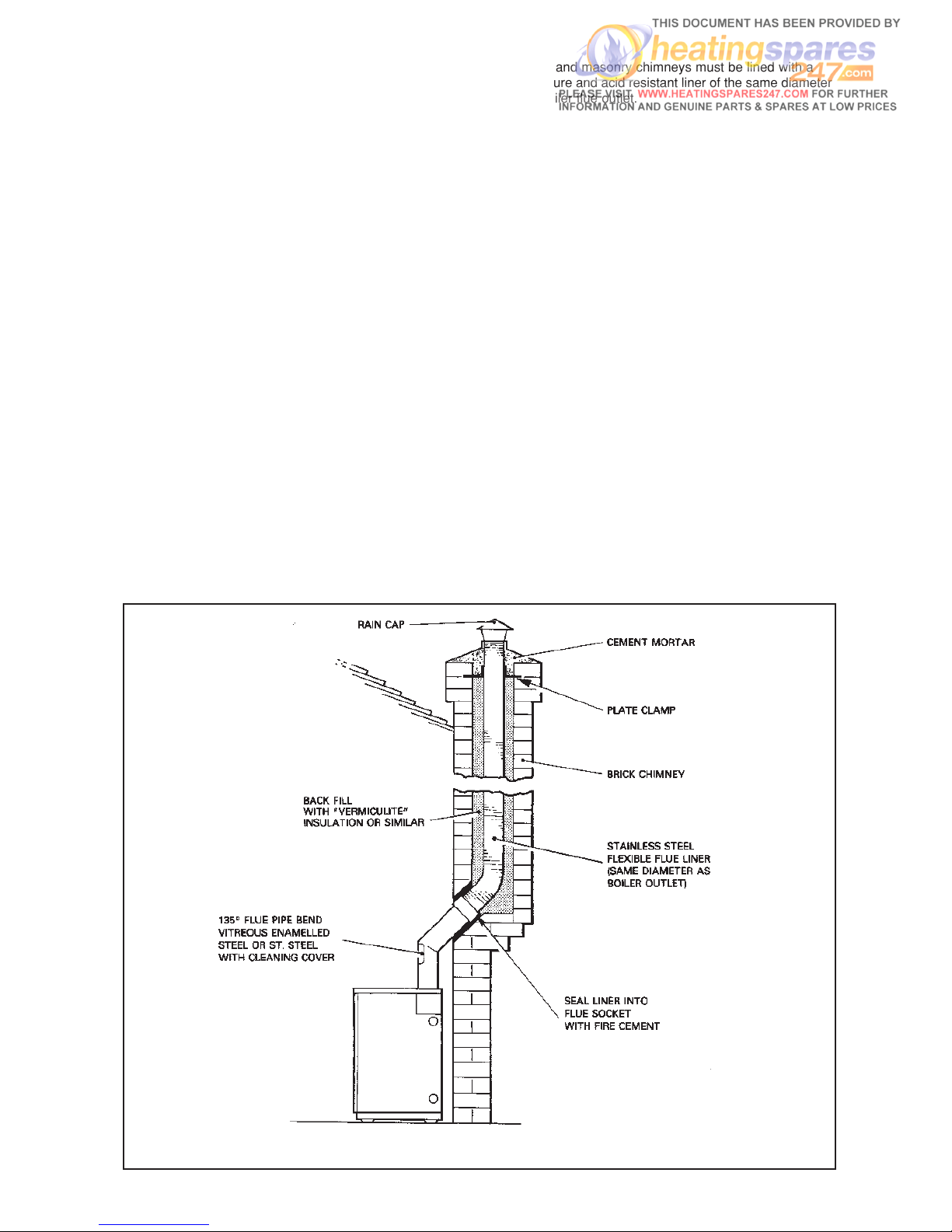
FIG.2 CONVENTIONAL BRICK CHIMNEY WITH LINER
3. FLUE SYSTEMS
Flue Socket Plate (conventional flue only)
The flue socket plate is packed separately in the burner/
thermostat box - to fit:
1. Remove four top casing retaining screws.
2. Remove top casing
3. Place flue socket plate in position on top of gasket.
4. Replace top casing using four screws.
Reference should also be made to BS 5410 Part 1 if further
information is required on conventional chimneys.
Conventional chimney (Fig. 2)
(a) The chimney should rise as vertically as possible and
terminate at a point not subject to down draughts or
wind eddies.
b) Brick and masonry chimneys must be lined with a
moisture and acid resistant liner of the same diameter
as boiler flue outlet.
The use of a flexible stainless steel liner is a convenient
method of lining brick and masonry chimneys.
A flexible liner should also be used in chimneys fitted with
large diameter clay liners to reduce the flue bore and
improve the thermal insulation.
Notes:
(1) In view of the EuroTrader’s high thermal efficiency,
it is important that a liner is fitted, otherwise
condensation problems could result.
(2)
Before fitting a liner, the chimney must be
thoroughly cleaned free from all traces of soot
and scale.
(c) A factory made insulated chimney complying with
BS 4543 Part 3 may be considered as an alternative
to a structural chimney both for new and existing
buildings.
(d) The in-built flue gas resistance of the EuroTrader is
such that it allows the boiler to operate reliably over
the wide range of chimney draughts encountered
from typical domestic chimneys.
(e) We would recommend the back filling of flues with
‘vermiculite’ to ensure maximum efficiency.
The use of a draught-stabiliser should not be necessary
nor is it desirable since it allows flue noise to be emitted
into the room and it could cool the chimney condensing
conditions.
Oil De-aerator Single pipe supply
Where a two pipe suction lift system is required, but the
return pipe is too long, or impractical to run, an Oil Deaerator can be used. The burner is piped as for a two
pipe system up to the Oil De-aerator but only a single
pipe is required from oil storage tank. A none-return
valve is not required with this system but the bypass plug
must be fitted in the pump as for a two pipe system.
The Oil De-aerator which should be fitted close to but not
inside the boiler casing, is available from most Builders
Merchants and some Oil Tank manufacturers.
Page 11
8
Note (1) The terminal should be positioned so as to avoid
products of combustion entering the building.
Note (2) If the terminal is less than 2 metres above the
ground level, balcony or place to which any
person has access, the terminal must be
protected by a guard.
Note (3) The flue must be positioned so that it does not
cause nuisance and permits the dispersal of
combustion products.
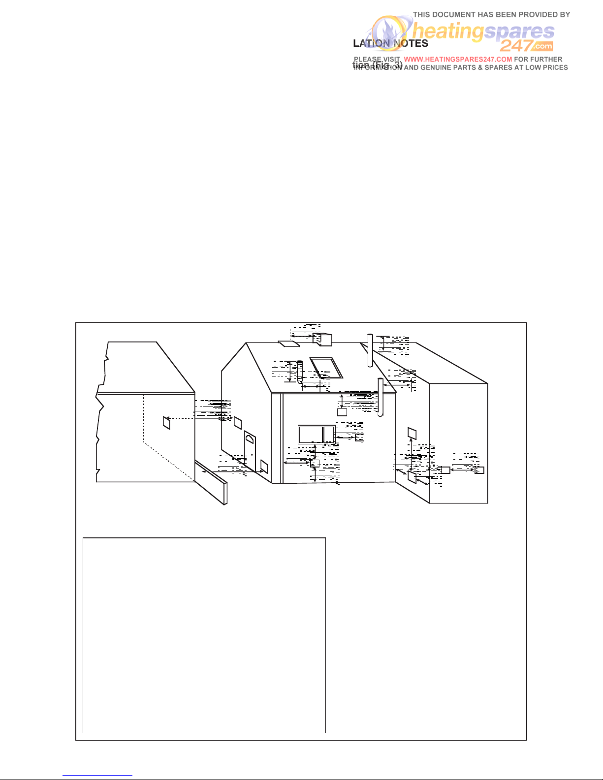
RECOMMENDED MINIMUM DISTANCES
FOR TERMINAL POSITION
FIG. 3 TERMINAL POSITION
Appliance burner type - Pressure Jet
Minimum distances to terminals in millimetres as measured from top of chimney
or the rim of a low level discharge opening
A Directly below an opening, air brick, window etc 600
B Horizontally to an opening, air brick, window etc 600
C Below a gutter, eaves or balcony with protection 600
D Below a gutter or balcony without protection 600
E From vertical sanitary pipework (*600) 300
F From an internal or external corner
(*600) 300
G Above ground or balcony level
(*600) 300
H From a surface or boundary facing the terminal 600
J From a terminal facing the terminal 1200
K Vertically from a terminal on the same wall 1500
L Horizontally from a terminal on the same wall 750
M Above the highest point of an intersection with the roof 600
N From a vertical structure on the side of the terminal 750
O Above a vertical structure less than 750mm from the side of the terminal 600
P From a ridge terminal to a vertical structure on the roof 1500
*Scotland 1990
Balanced Flue Systems
(optional extra)
The Trianco balanced flue system offers much greater
flexibility for siting, the boiler compared with a
conventional chimney. The only requirement is for a
suitable outside wall to fit the horizontal discharge
terminal or, alternatively, a single storey roof for a vertical
discharge.
In additional to the siting benefit, the performance of
balanced flue boilers is virtually unaffected by high wind
conditions since the wind pressures are applied equally
to both air intake and flue gas discharge, thus creating a
balanced condition.
Whereas some balanced flue boilers rely on case sealing
to achieve a room seal, Trianco boilers have a sealed air
duct system which maintains the room sealed
performance even when the casing door is removed for
burner commissioning or adjustments.
The use of the balanced flue principle also enhances the
overall thermal efficiency of the boiler since the incoming
air extracts waste heat from the flue and returns it as
pre-heated air to the burner where it aids combustion.
INSTALLATION NOTES
(a) Location (Fig. 3)
Modern balanced flue boilers are designed to
operate at low noise levels. However, when
positioning your boiler, it is not recommended to
have the terminal facing a neighbours property
or patio etc. It should also be positioned to avoid
products of combustion entering the building.
(b)
Flue Sealing
As the flue system operates under positive
pressure, it is essential to seal all flue joints.
Apply a thin bead of silicone sealant (supplied)
around flue pipe spigot before inserting into
socket and all other joints.
(c)
Fuel
Only Kerosene 28 sec. Class C2 is permitted for
boilers using low level flue discharge.
(d)
Important
Trianco Balanced Flue Kits have been designed
primarily to use with Trianco boilers and as such
compatibility with other makes of boiler cannot
be guaranteed.
Page 12
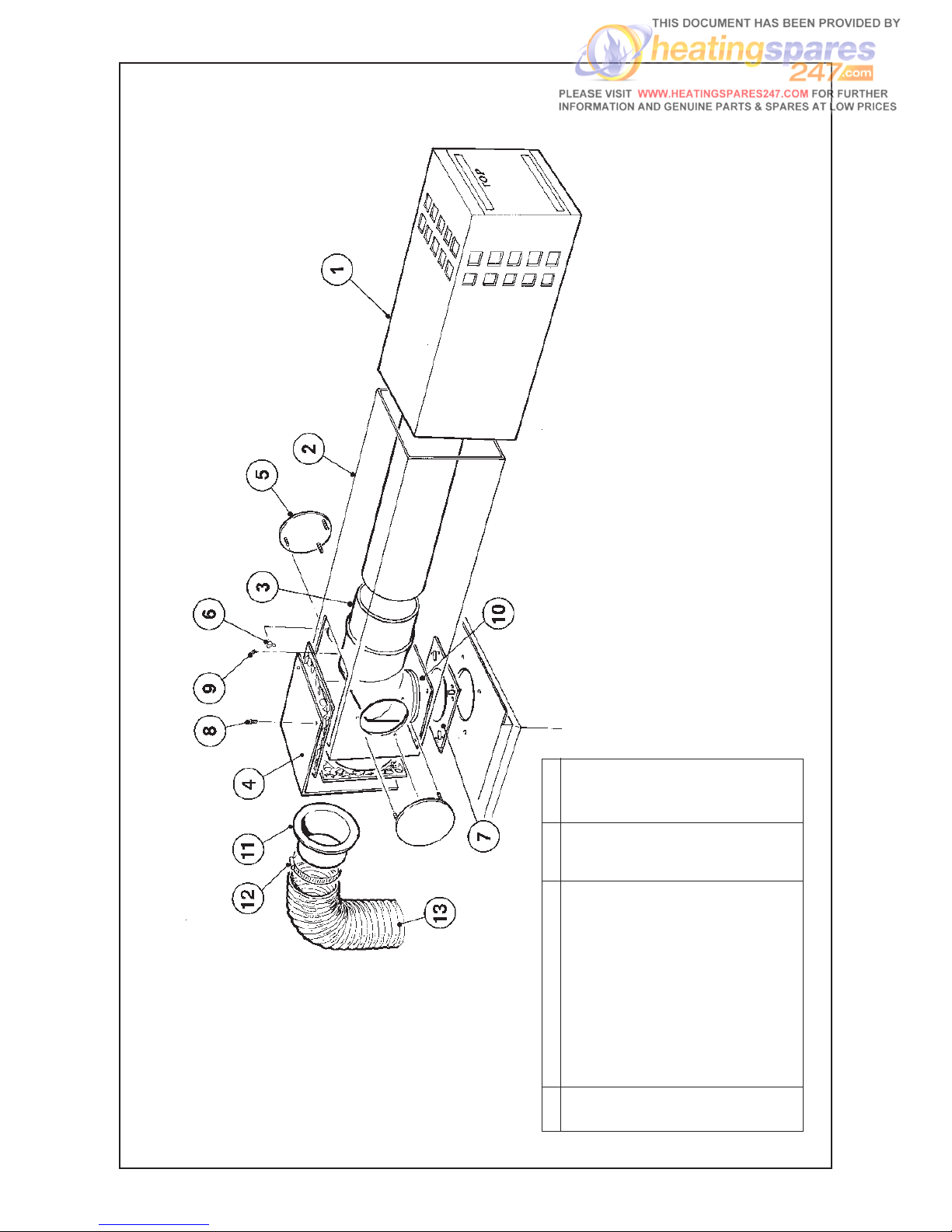
Fig. 4
Item Description Part no. No. Off
1 Flue terminal 208540 1
2 Flue Box 208555 1
3 Flue elbow 208547 1
4 Blanking plate 208554 1
5 Round sealing plates 208551 3
6 M4 wing nut 94380 9
7 Blanking plate gasket 208559 3
8 No. 6 x 12mm STS Hex. HD 91601 2
9 No. 6 x 12mm STS Pozi. HD 91523 6
10 Inner flue pipe spigot plate 208566 1
11 Air hose spigot 206933 1
12 Clip 95256 1
13 Hose fitted on boiler 20693 1
- 208575 on 2271 kit only
- 221731 on 2271 kit only
9
Page 13
50/90 715mm
100/125 775mm
50/90 715mm
100/125 775mm
Fig. 5
10
7”
175mm MIN
18” 455mm
MAX
23”
585mm MIN
33” 850mm
MAX
Page 14
11
267mm
343mm
300mm
All sizes in mm approximate.
TERMINAL GUARDS
When the terminal is positioned where there is the
possibility of accidental contact by persons, or of damage
to the terminal, an approved guard is necessary.
Generally, exhaust 2 metres above ground level
alleviates the necessity for a guard.
A suitable guard is available from Trianco,
part NO. 204123
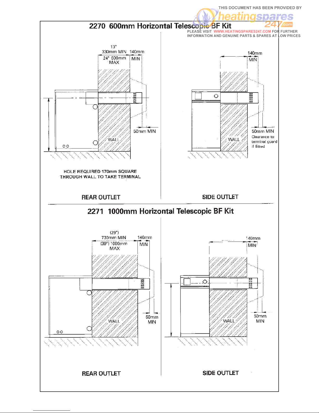
600mm HORIZONTAL TELESCOPIC BF KIT
ASSEMBLY METHOD (Fig 4/5)
1. Having decided the position of the boiler cut a
hole 170mm square in the wall.
2.
Remove the top casing and the flue socket from the
top of the boiler. Ensure that the gasket is on top of
the boiler and then place the white flue box on top of
the gasket. Fit the stainless steel flue spigot plate into
flue box and screw to the top of the boiler, trapping
the gasket and box in position.
3. Fit the flue elbow to the stainless steel pipe on the
terminal. Slide the terminal into the flue box from the
outside and locate the elbow over the spigot plate.
4. Measure from the face of the outside wall to the end
of the terminal. Subtract 140mm. This will give the
length that requires cutting from the terminal inner
pipe.
5. Remove the terminal form the flue box, remove the
elbow from the pipe and then cut the terminal pipe to
the required length. Replace the elbow in the end of
the pipe and slide the terminal into the flue box,
locating the elbow securely onto the spigot.
6. When terminating from the rear of the boiler, fit the air
hose spigot over the hole in the L-shaped blanking
plate, securing it with the M4 wing nuts provided.
When terminating from the side of the boiler, fit the air
hose spigot to the side of the flue box.
7. Fit the L-shaped blanking plate to the flue box. Blank
off the remaining holes with the round sealing plates,
using silicone sealant and the M4 wing nuts.
8. Fit the air hose between the burner and the spigot on
the flue box, securing it using the clips provided.
9. Close any gaps around the terminal on both sides of
the wall and replace the top casing.
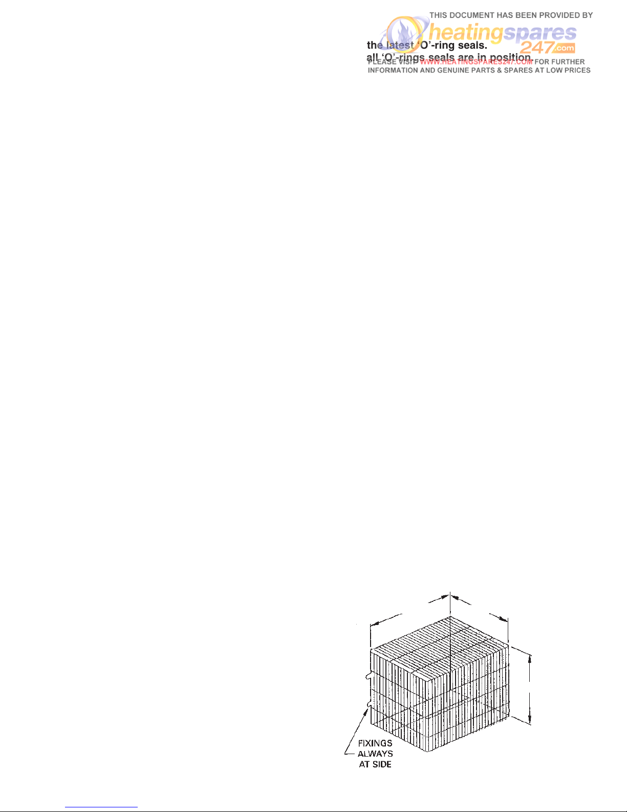
Trianco flue kits are designed to incorporate the latest ‘O’-ring seals.
Before commencing assembly, please make sure that all ‘O’-rings seals are in position.
1000mm HORIZONTAL TELESCOPIC BF KIT
ASSEMBLY METHOD (Fig 4/5)
1. Having decided the position of the boiler
, cut a hole
170mm square in the wall.
2. Remove the top casing and the flue socket from the
top of the boiler. Ensure that the gasket is on top of
the boiler and then place the white flue box on top of
the gasket. Fit the stainless steel flue spigot plate into
the flue box and screw to the top of the boiler,
trapping the gasket and box in position.
3. Fix the flue elbow to the stainless steel pipe of the
terminal. Slide the terminal into the flue box from the
outside and locate the elbow over the spigot plate.
4. Slide the terminal inwards over the elbow pipe until it
is in the position required, making sure that there is a
minimum distance of 140mm from the outside wall to
the end of the terminal.
5. When terminating from the rear of the boiler, fit the air
hose spigot over the hole in the L-shaped blanking
plate, securing it with the M4 wing nuts provided.
When terminating from the side of the boiler, fit the air
hose spigot to the side of the flue box.
6. Fit the L-shaped blanking plate to the flue box. Blank
off the remaining holes with round sealing plates,
using silicone sealant and the M4 wing nuts.
7. Fit the air hose between the burner and the spigot on
the flue box, securing it using the clips provided.
8. Close any gaps around the terminal on both sides of
the wall and replace the top casing.
IMPORTANT: TO AID ASSEMBLY, IT IS NECESSARY
TO APPLY A THIN BEAD OF LUBRICANT (E.G.
WASHING - UP LIQUID OR VASELINE) TO ALL
FLUE
JOINTS THAT INCORPORATE ‘O’- RING SEALS.
AS THE FLUE SYSTEM OPERATES UNDER
POSITIVE PRESSURE, ALL FLUE JOINTS THAT DO
NOT INCORPORATE ‘O’- RING SEALS SHOULD BE
SEALED WITH SILICONE SEALANT.
Page 15
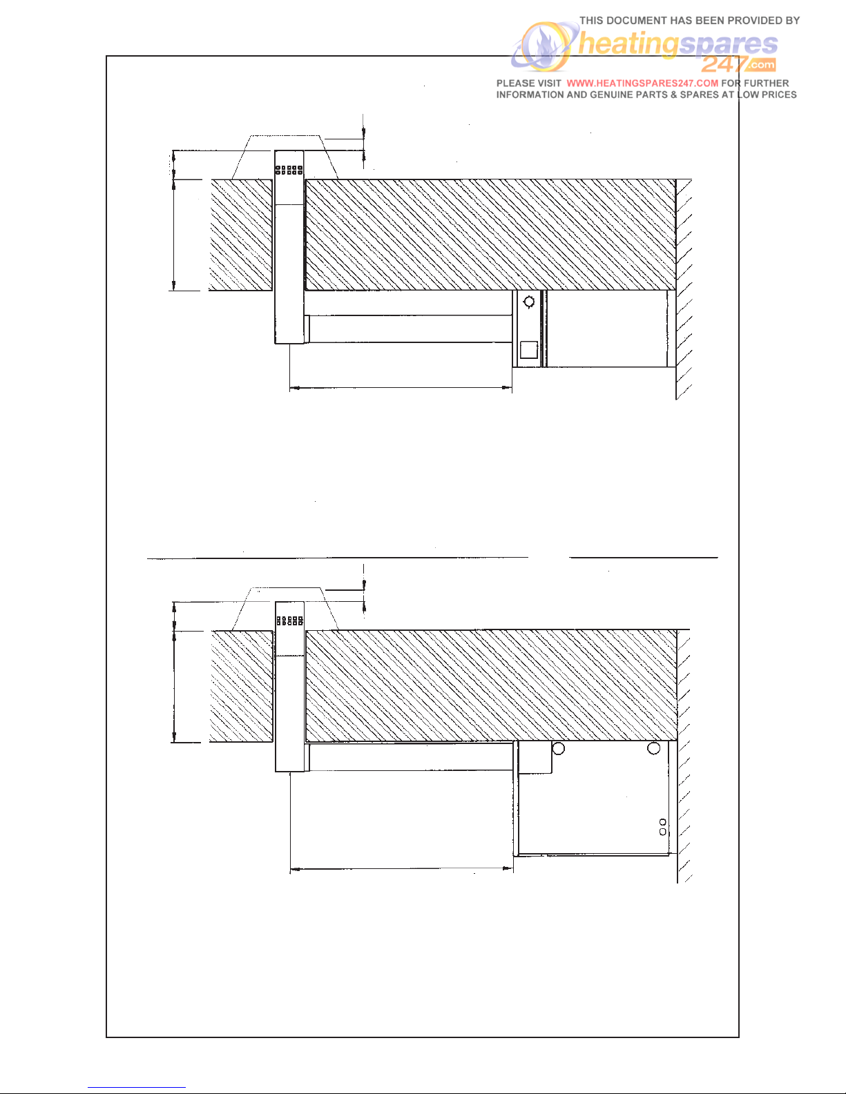
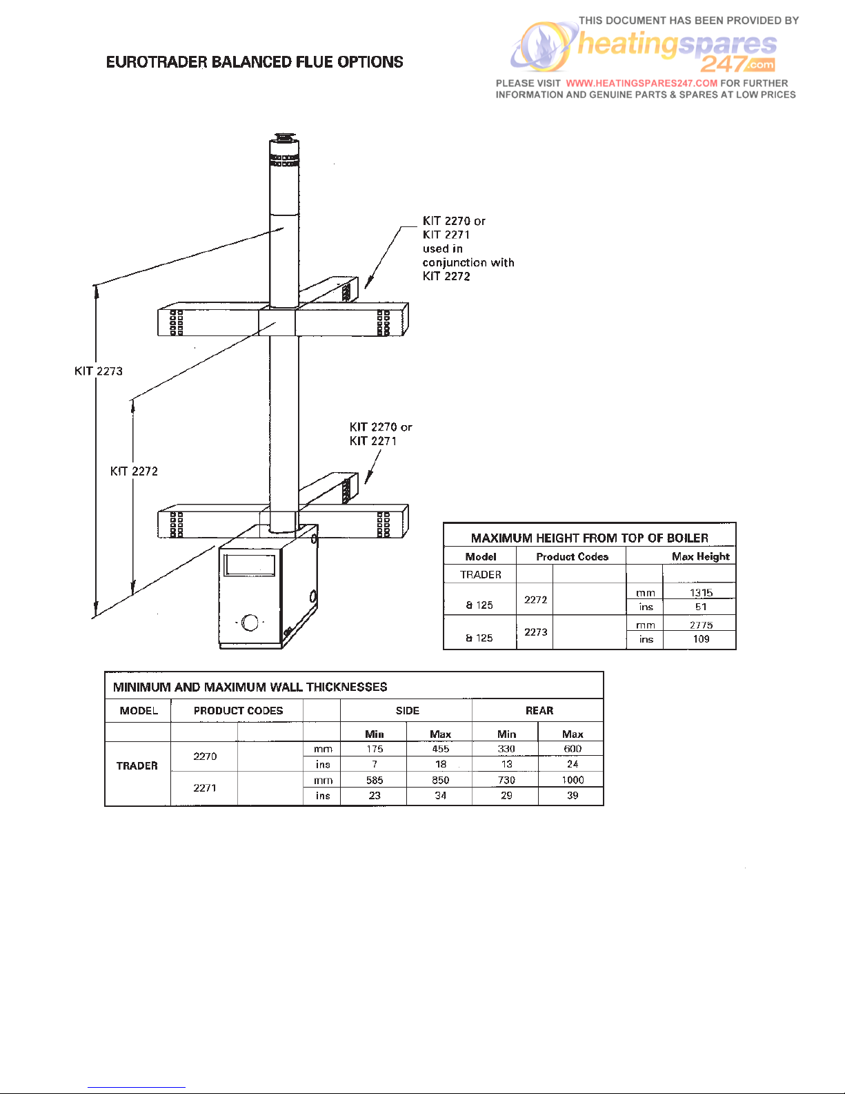
2272 HIGH LEVEL ADAPTOR KIT USED IN CONJUNCTION WITH 2270 OR 2271
50/90 (42'') 1060mm
100/125 (43'') 1095mm
50/90 (42'') 1060mm
100/125 (43'') 1095m
(Dimension ‘A’)
KIT 2270
(7'') 175mm MIN
(18'') 455mm MAX
KIT 2271
(23'') 585mm MIN
(33'') 850mm MAX
REAR OUTLET
SIDE OUTLET
HOLE REQUIRED 170mm SQUARE
THROUGH WALL TO TAKE TERMINAL
(2'')
50mm
MIN
(2'')
50mm
MIN
140mm
MIN
140mm
MIN
DIM ADIM A
(Dimension ‘A’)
KIT 2270
(13'') 330mm MIN
(24'') 600mm MAX
KIT 2271
(29'') 730mm MIN
(39'') 1000mm MAX
Fig. 6
12
Page 16

13
ASSEMBLY METHOD (Fig 6/7) - High Level Adaptor Kit used with 600mm Horizontal Telescopic BF Kit
Supplied with the kit are two spigots. Use the spigot that does not have chamfered corners. The other spigot is
not required for this installation. Each vertical section of pipe has a different diameter. The lowermost pipes have
the smallest diameter, the uppermost the largest.
To aid assembly, it is necessary to apply a thin bead of lubricant (e.g. washing up liquid or Vaseline) to all flue
joints that incorporate ‘O’-ring seals. As the flue system operates under positive pressure, all flue joints that do
not incorporate ‘O’-ring seals should be sealed with silicone sealant.
Trianco flue kits are designed to incorporate the latest ‘O’-ring seals.
Before commencing assembly, please make sure that all ‘O’-rings seals are in position.
1. Having decided the position of the boiler, cut a 170mm
square hole in the wall.
2. Take the collar piece and slide onto the top inner flue
pipe (identified by lack of plate connection piece at
base), making sure that the stop pieces are closest
to the top of the collar
. Line up the holes in the collar
with the holes in the flue pipe and screw the collar
into position using self-tapping screws.
3. Remove the top casing and remove the spigot plate
from the top of the boiler. Place gasket on top of the
boiler and then the inner flue pipe over the gasket.
Use spigot plate (previously removed) as a clamping
plate. Screw it down on top of the boiler, trapping the
pipe and gasket in position.
4. Place outer lower pipe (identified by hose connection
piece) over inner lower pipe (identified by flat spigot
connection at base) and fit onto spigot plate.
5. Fit top inner flue pipe to lower flue pipe, using holes
provided. Fit outer pipes together in same manner.
making sure that top outer and inner pipes are level
with each other.
6. Take the flue box and to the underside of the box
(identified by twelve holes around the square cut
out), fit the flue pipe spigot and gasket.
7. Slide the flue box through the cut out in the wall and
locate outer flue pipe to the spigot on the flue box.
8. Slide telescopic inner flue pipe over inner flue pipe of
flue terminal. Fix flue elbow onto end of telescopic
inner pipe and slide terminal into the flue box from
outside, locating elbow over collar piece.
9. Push terminal inwards. A minimum dimension of
140mm from the wall to the end of the terminal is
required.
10. Fit round sealing plates in position on flue box using
silicone sealant and M4 wing nuts.
11. Fit round sealing plates onto blanking plate and
secure using four self-tapping screws.
12. Make good wall inside and outside.
13. Use clip provided to secure air hose from burner to
connection on flue pipe.
14. Replace top casing.
1. Having decided the position of the boiler, cut a 170mm
square hole in the wall.
2. Take the collar piece and slide onto the top inner flue
pipe (identified by lack of plate connection piece at
base), making sure that the stop pieces are closest
to the top of the collar
. Line up the holes in the collar
with the holes in the flue pipe and screw the collar
into position using self-tapping screws.
3. Remove the top casing and remove the spigot plate
from the top of the boiler. Place gasket on top of the
boiler and then the inner flue pipe over the gasket.
Use spigot plate (previously removed) as a clamping
plate. Screw it down on top of the boiler, trapping the
pipe and gasket in position.
4. Place outer lower pipe (identified by hose connection
piece) over inner lower pipe (identified by flat spigot
connection at base) and fit onto spigot plate.
5. Fit top inner flue pipe to lower flue pipe, using holes
provided. Fit outer pipes together in same manner,
making sure that top outer and inner pipes are level
with each other.
6. Take the flue box and to the underside of the box
(identified by twelve holes around the square cut
out), fit the flue pipe spigot and gasket.
7. Slide the flue box through the cut out in the wall and
locate outer flue pipe to the spigot on the flue box.
8. Fix flue elbow onto flue box inner pipe and slide
terminal into the flue box from outside, locating elbow
over collar piece.
9. Measure from the face of the outside wall to the end
of the terminal and subtract 140mm. This will give the
length of pipe to be cut off of the flue terminal inner
pipe.
10. Remove the flue terminal from the flue box and
remove the elbow. Cut the terminal inner pipe to the
desired length and reassemble flue.
11. Fit round sealing plates in position on flue box using
silicone sealant and M4 wing nuts.
12. Fit round sealing plates onto blanking plate and
secure using four self-tapping screws.
13. Make good wall inside and outside.
14. Use clip provided to secure air hose from burner to
connection on flue pipe.
15. Replace top casing.
ASSEMBLY METHOD (Fig 6/7) - High Level Adaptor Kit used with 1000mm Horizontal Telescopic BF Kit
Page 17
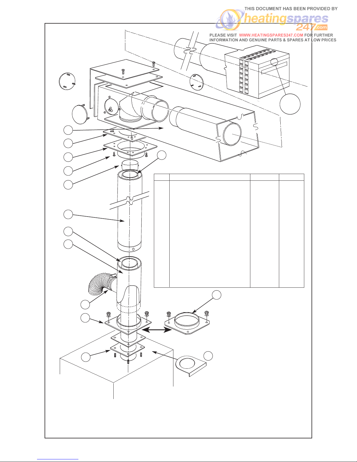
14
TOP
1
13
2
3
4
5
6
7
8
9
14
11
12
10
Item Description Part no. No. Off
1 600mm or 1000mm Horizontal Kit 2270 or 2271 1
2
Flue spigot terminal to outer 221716 1
3 No 6 Self tapping screws 91523 17
4 Outer flue pipe - Long 221725 1
5 Inner flue pipe - Short 221668 1
6 Outer pipe with hose connection 221662 1
7 Jubilee clip
(supplied with either 2270 or 71)
95256 2
8 Flue socket plate
(supplied with boiler)
207772 1
9 Gasket
(supplied with boiler)
204072 1
10 Collar piece 211707 1
11 Flue spigot boiler to outer
(WM70 ONLY)
221648 1
12 Inner flue pipe - Long 221726 1
13 Gasket
(supplied with kit)
208559 3
14 Flue infill plate 209597 1
- Inner ‘O’ ring 221647 3
- Outer ‘O’ ring 221666 3
Fig. 7 2272 UNIVERSAL HIGH LEVEL BF ADAPTOR KIT
Page 18
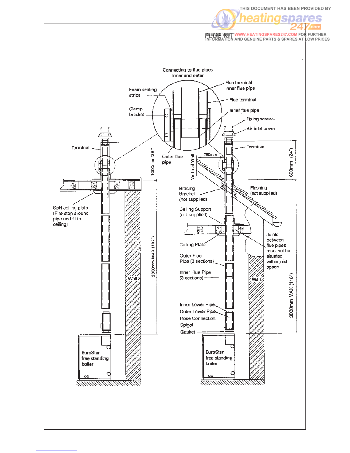
FLAT ROOF
PITCHED ROOF
2273 VERTICAL BALANCED FLUE KIT
Fig. 8
15
Page 19

16
IMPORTANT: FLUE SEALING
TO FIT FLUE PIPES TOGETHER THAT INCORPORATE ‘O’ RING SEALS, IT IS ESSENTIAL TO APPLY A THIN BEAD
OF LUBRICANT (E.G. WASHING UP LIQUID, VASELINE) AROUND ALL RUBBER SEALING RINGS.
AS THE FLUE SYSTEM OPERATES UNDER POSITIVE PRESSURE, IT IS ESSENTIAL TO ACHIEVE
A TOTAL SEAL ON FLUE JOINTS. APPLY A THIN BEAD OF SILICONE SEALANT AROUND
THE BASE OF FLUE PIPE BEFORE INSERTING INTO BOILER SPIGOT.
EXPOSED PIPE:
ANY PIPE EXPOSED TO THE ELEMENTS SHOULD BE PROTECTED WITH A SUITABLE MATERIAL.
WHEN ASSEMBLING THIS KIT, PLACE ALL WELD SEAMS TO THE REAR.
ASSEMBLY METHOD (Fig.8/9)
1. Having secured the boiler in position cut a hole
175mm diameter or square in the ceiling and roof.
2. Remove top casing of boiler and remove the flue
socket from the top of the boiler body.
3. Determine the flue length required, ensuring that the
top outer flue pipe will finish above the roof flashing
line. If possible, pre-assemble the entire flue on a flat
surface. Use the pre drilled holes at the base of each
pipe to drill 2.8mm diameter holes near the top of
each pipe for use with the self-tapping screws.
Note: The lowermost inner pipe will protrude from the
top of the lowermost outer pipe by approximately
40mm to ensure easy accessibility when fixing the
inner pipes together
. The bottom sections already
have pre-drilled holes, located near to the top of the
pipes.
The flue spigot plate must fit over the inner lower pipe
before the outer lower pipe is put in position.
The flue infill plate is placed on the top casing (once
replaced), however it should be fitted around the
outer pipe before the full flue is assembled.
4. If possible to do so, lift the entire assembled flue
through the ceiling and secure in position on top of the
boiler
. Fasten down with existing nuts and washers.
Vertical Balanced Flue Kit
The vertical balanced flue kit is designed to be telescopic in nature and incorporates the latest ‘O’ring seals. It is
therefore unnecessary for any ‘cutting down’ of pieces to the required size.
Please note that to facilitate the connection process, each section of pipe has a different diameter. The lowermost
pipes have the smallest diameter, the size increasing with each subsequent section of pipe. The lowermost pipes
are also the shortest, with the subsequent inner and outer sections being the next shortest. The next sections are
all the same length, however the highest inner and outer pipes have a single hole at the top above the ‘O’ ring seal.
Before commencing the assembly process, please make sure that you have correctly identified the placement of
each pipe section and that all ‘O’ ring seals are in position.
5. If this is not possible, then fit the flue piece by piece,
being aware that none of the flue joints should be
situated within the joist space.
Note: The air inlet holes on the terminal must not be
blocked on the outside, or on the inside by the upper
flue pipe.
6. Fit ceiling plate centrally over hole, ensuring that the
outer flue pipe has a minimum clearance of 25mm
from any combustible material. Pack space with glass
fibre insulation.
7.
Fix pipe bracket (where necessary) to roof space and
fit waterproof flashing (not supplied) around outer flue
pipe at roof line.
8. Fit clamping strap (supplied) around joint line of
terminal and upper flue pipe. Use foam sealing strip
inside clamping strap.
9. Fit the apron cravat (air inlet cover) to the terminal
using 4 self-tapping screws (supplied).
10. Use clip provided to secure air hose from burner to
connection on the outer lower pipe.
11. Replace top casing.
Page 20
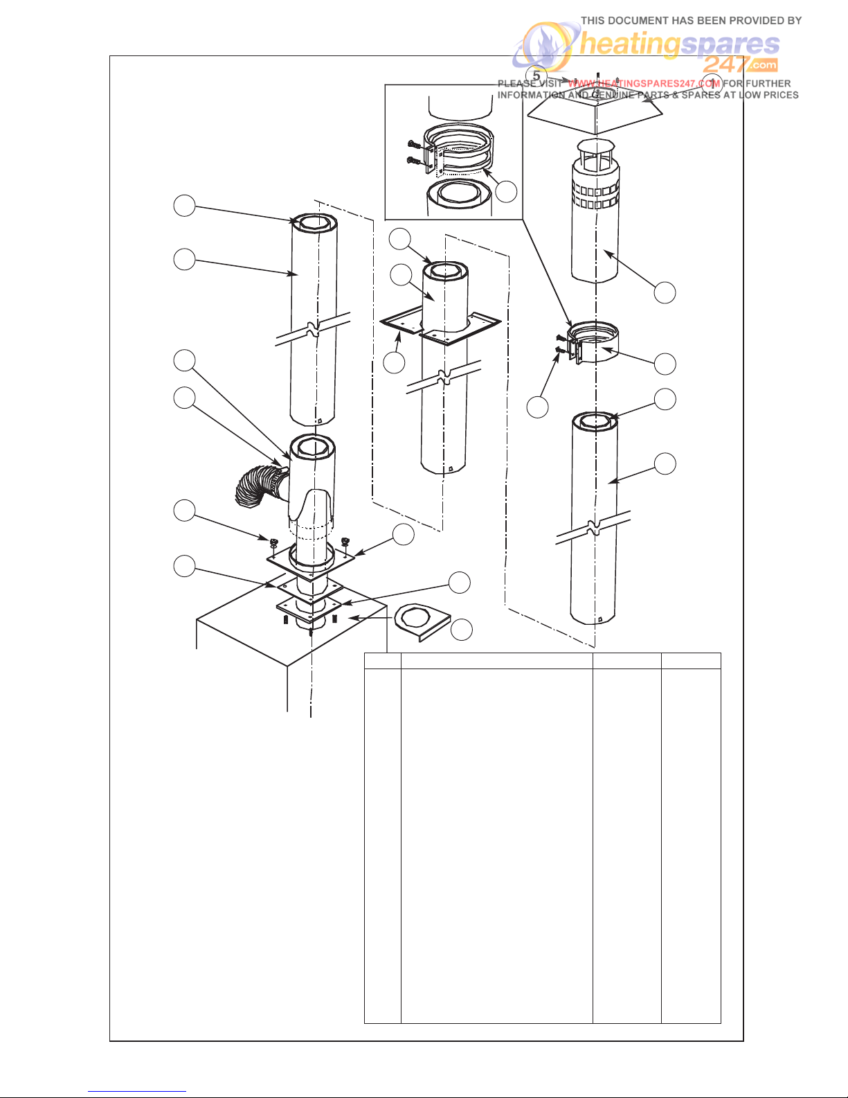
17
14
15
6
5
1
2
3
18
19
4
8
9
20
16
17
7
13
12
11
10
Item Description Part no. No. Off
1 Apron Cravat 221674 1
2
Vertical terminal silencer 221672 1
3 Clamping strap 221673 1
4 M4 x 35 Pan head Pozi - 4
5 No. 8 Self tapping screw - 4
6 Silicone sponge 98112 2
pcs
7 Ceiling plate half 208583 2
8
Flue socket plate
(supplied with boiler)
207772 1
Flue socket plate
(WH70 only)
221648 1
9 Gasket
(supplied with boiler)
204072 1
10 Inner pipe bottom lower section 221668 1
11 M6 nuts & washers - 4
12 Jubilee clip 95256 2
13 Outer flue pipe with hose connection 221662 1
14 Inner pipe lower section 221726 1
15 Outer pipe lower section 221725 1
16 Inner pipe middle section 221669 1
17 Outer pipe middle section 221665 1
18 Inner pipe top section 221670 1
19 Outer pipe top section 221667
20 Flue infill plate 209597 1
- Inner ‘O’ ring 221647 4
- Outer ‘O’ ring 221666 4
{
Fig. 9
2273 UNIVERSAL VERTICAL
BALANCED FLUE KIT
Page 21
Oil Pipe Connections
The burner is supplied for use with a one pipe oil supply system. If used on a two pipe system, it is necessary
to fit the by-pass plug in the oil pump.
It is essential that for reliable operation and a condition
of the guarantee that an oil filter with a maximum mesh
of 70ppm is fitted in the oil pipe from the tank to the
burner, as close to the boiler as possible but NOT inside
the boiler casing. A fire valve MUST also be fitted in the
oil supply line, preferably where it enters the building.
18
50/90
50/90
50/90 &
100/125
FIG 10
Page 22
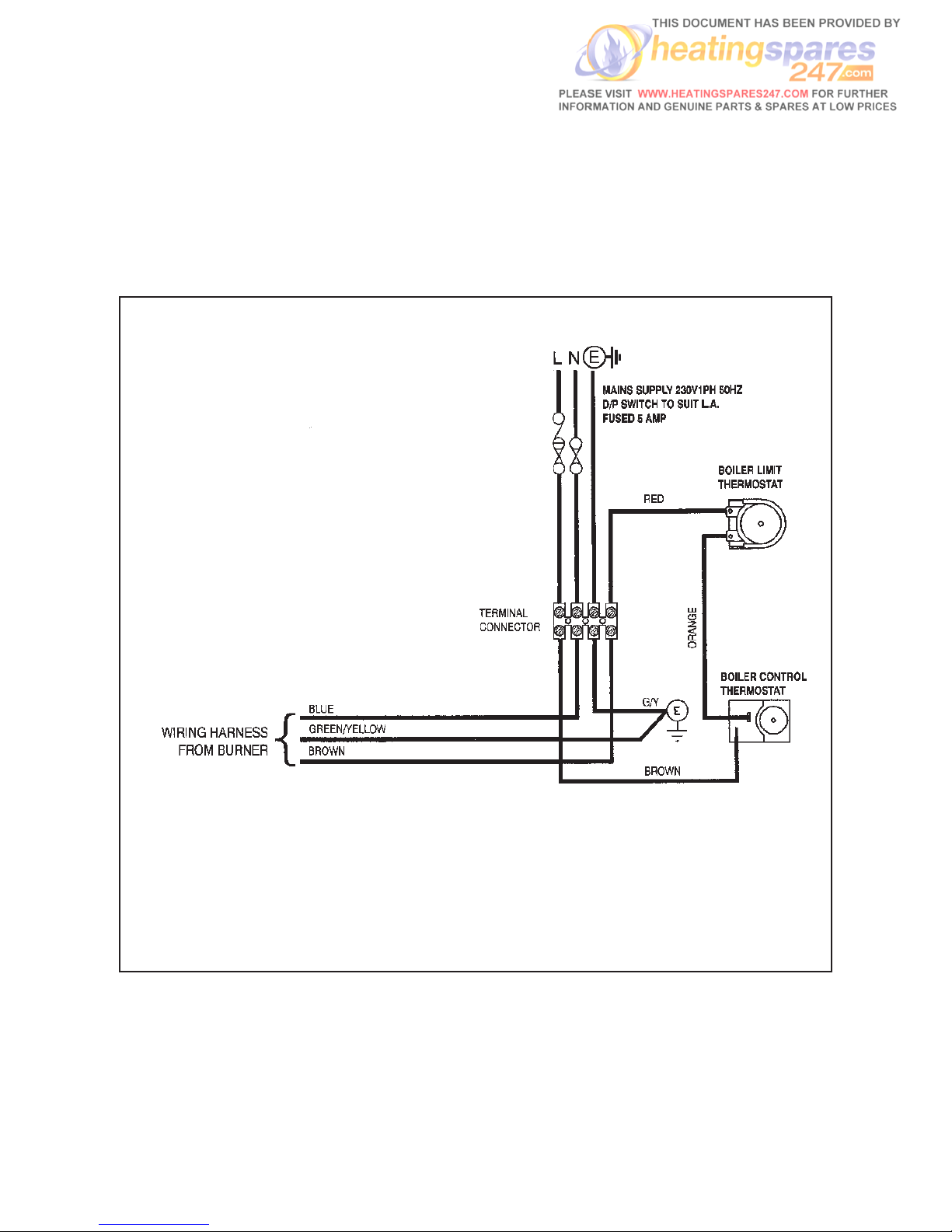
4. ELECTRICAL
Control Box Installation
Electricity Supply 230V, Single Phase 50Hz
All wiring to supply and all system components external to
the boiler must comply with the latest edition BS 7671 IEE
Wiring Regulations.
Insert thermostat phial into the top phial pocket on the
L/H side of the boiler making sure not to trap the thermostat capillary. Secure control box to top L/H side of
boiler fixing with one screw.
19
Fig. 11 WIRING DIAGRAM
Page 23
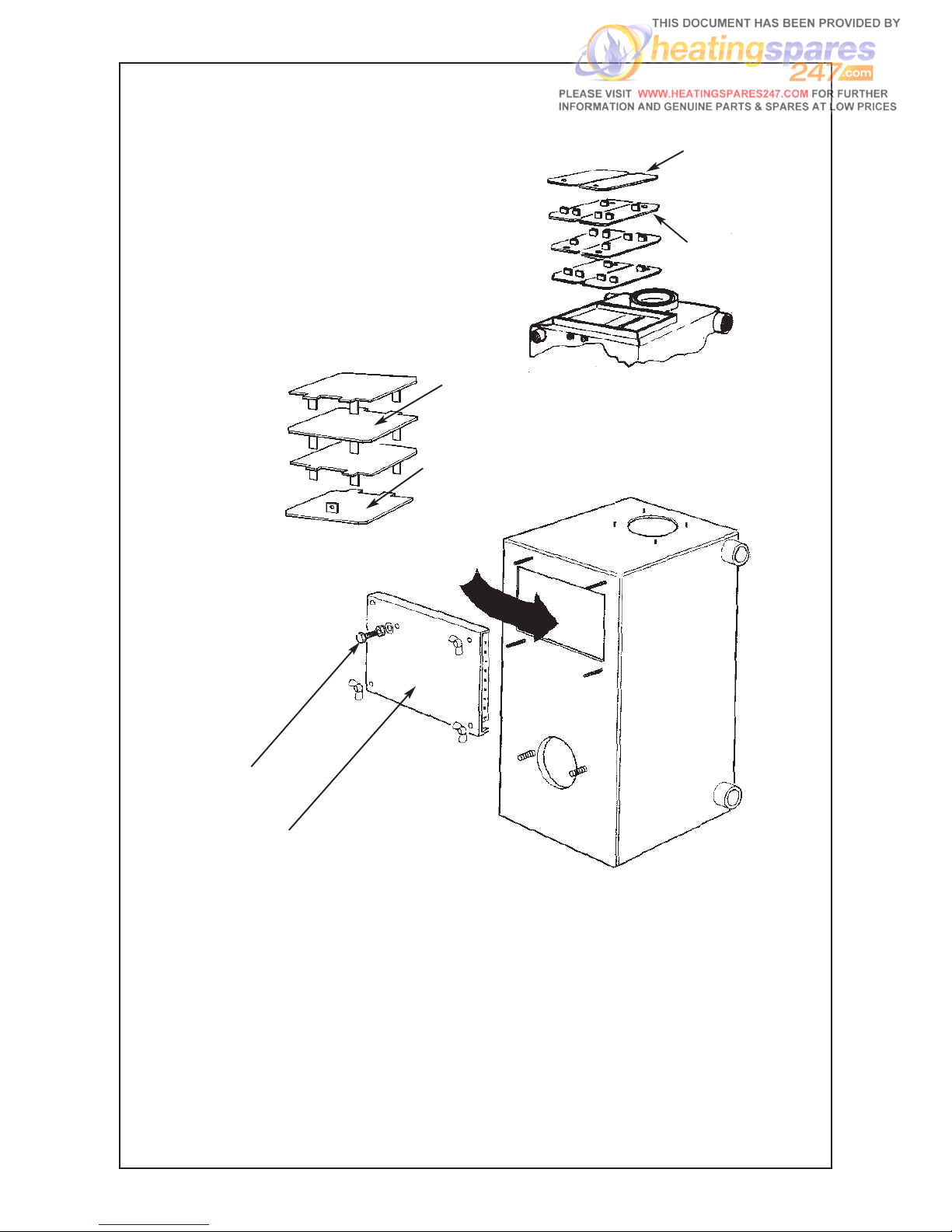
FIG. 12 BAFFLE DETAILS
EuroTrader 125
BAFFLE ARRANGEMENT
PART NO.
208865
2-OFF
PART NO.
208871
6-OFF
FLUE GAS
SAMPLING POINT
20
BAFFLES MUST BE FITTED IN
THE ARRANGEMENT SHOWN
i.e. GAP ALTERNATING FROM
BACK TO FRONT
FLUE
COVER
EuroTrader 50/90
BAFFLE
ARRANGEMENT
PART NO.
208838
3-OFF
PART NO.
208834
1-OFF
Page 24

21
5. COMMISSIONING
It is the responsibility of the installer to ensure the boiler
is properly commissioned, failure to do so will make the
boiler’s guarantee and any extended warranty null and
void.
Although all burners are factory tested before
despatch, they will usually need further air adjustment to achieve the readings indicated in ‘Burner
detail leaflet’
because of site variations in flue
draught and back pressure.
Procedure
1. Switch off electrical supply to the boiler.
2. Ensure boiler is full of water and all valves are open.
3. Remove flue-cover and check that flue-baffles are
correctly positioned (See Fig 12 for baffle arrangement).
4. Disconnect oil hose from burner, open shut-off valve
and run off a quantity of oil into a container to check
for a clean air free supply then reconnect hose. (This
applies to single pipe gravity system only).
5. Check that the time-switch (if fitted) is in the ON
position and room and boiler thermostats are calling
for heat.
6. Switch on electrical supply and the burner should
start.
Note: The burner may lock-out on first firing due to
air in the pump, if this happens, wait about a minute
before pressing reset button to restart burner. If a
further lock-out occurs, the air should be bled from
the pump pressure gauge connection.
7. Start and stop the burner two or three times until
the flame cuts off sharply - this indicates any
remaining air has been dispersed.
8.
Allow the burner to run for about 15 minutes, then
take a CO
2
reading through the sampling hole in
flue-cover. Compare the reading with that given
under ‘Burner Settings’ and adjust the air setting if
necessary to achieve the required CO
2
%. Also,
check the smoke and flue gas temperature.
Handing Over
After completing the boiler installation, the installer
should make a thorough check of the system to ensure it
is completely satisfactory and demonstrate to the user
the operation of the boiler and any system controls.
All instructions should be handed to the user for retention
and advice regarding the need for annual servicing.
Air Adjustment
The air damper is factory set at a nominal position to
suit typical conventional flue conditions. However
because of variations in flue draught it will usually be
necessary to slightly adjust the air damper in order to
achieve the CO2 level indicated under ‘Burner Setting’.
N.B. When used with a Trianco Balanced Flue it will be
necessary to increase the air setting by 2 to 3 divisions
in order to obtain the correct CO2 level with zero smoke
reading.
The adjustment can be carried out by removing the end
cover from the burner and using a 4mm Allen Key rotate
screw 16 - clockwise to increase air lowering the CO2
and anticlockwise to raise CO2.
The air should be reduced until there is just a trace of
smoke (measured with a smoke pump) then opened
slightly to achieve a zero smoke reading. This provides
the optimum setting.
Page 25

22
Servicing the Boiler
(Burner removed)
1. Remove flue-cover and lift out flue-baffles
(See Fig. 12).
2. Brush all deposits from flue-baffles and internal
surfaces of the boiler.
3. Remove flue deposits from the combustion chamber
floor using a vacuum cleaner.
4. Replace flue-baffles in the correct arrangement
(See Fig. 12 for order of assembly). Refit the fluecover and fully tighten wing-nuts to make a gas tight
seal.
5. Refit burner to boiler, connect flexible air hose
(balanced flue boilers only) and plug-in burner lead.
6. Turn on oil supply, switch on electricity and burner
should fire.
7. Finally check the combustion readings with those
given under ‘Burner Settings’ and make any air or oil
pressure adjustments necessary.
6. SERVICING
IMPORTANT: ISOLATE ELECTRICAL SUPPLY TO THE
BOILER BEFORE SERVICING
To maintain the boiler’s high thermal efficiency and
reliable operation, it should be serviced annually by a
qualified engineer preferably OFTEC trained and
registered. Electrical work should be carried out by a
qualified engineer
.
If the boiler is used to provide central heating and hot
water all year round, the best time for its annual service
is just before the start of the heating season.
Where the boiler is shut down for the summer months,
the service should be carried out as soon as possible
after the end of the heating season.
Oil tank
Open tank drain-cock to draw off any accumulated water
and sludge.
Line filters
Turn off oil supply and remove filter bowl. Wash filter element clean with kerosene.
Servicing the burner
See separate leaflet ‘Burner Details’.
Page 26

23
7. FAULT FINDING
ELECTRICITY SAFETY - Before making any electrical checks, switch off mains supply to boiler.
FAULT POSSIBLE CAUSE ACTION
BURNER WILL NOT START Control box locked out - Light on Press reset button on front of burner.
N.B. ONLY TRY TWICE
Boiler thermostat or other system Ensure all controls are calling for heat.
controls satisfied
Fuse blown Fit new 5 amp fuse, if it blows again, check
for short circuit in wiring.
Check for live supply continuity up If live supply confirmed, change control box
to burner
Motor or pump seized Check for rotation and replace as
necessary.
BURNER STARTS No oil supply Check oil level in tank and feed to burner.
BUT FLAME NOT
ESTABLISHED Photo-cell not seeing flame Clean photo-cell and ensure it is fully
plugged in.
Air trapped in pump Bleed off air through pressure gauge
tapping.
Solenoid valve faulty Check coil for continuity and
replace if faulty.
Nozzle blocked Replace nozzle with one of same
specification.
Electrodes incorrectly set Reset gap and position
electrodes as shown in Burner diagram.
Electrode insulator cracked Check and replace if insulator cracked or
crazed.
Ignition transformer and H.T. Check for spark and condition of HT
contacts contacts. Replace as necessary.
Low oil pressure Check pump pressure and adjust to
correct setting.
FLAME ESTABLISHED Oil contaminated with water Run off oil at burner until free of
BUT BURNER LOCKS
water and drain condensation from tank
OUT AFTER FEW SECONDS
Oil filter partially blocked Wash filter clean with kerosene.
Photo-cell fault Clean photo-cell and ensure
it is fully plugged in. Replace if faulty.
Oil pressure low Check pump pressure and adjust
to correct setting.
POOR FLAME CUT-OFF Air in pump or at back of nozzle Bleed pump through pressure gauge port,
also check for leaks in oil line if 2-pipe
system.
Oil contaminated with water Run off oil at burner until free of water and
drain condensation from tank.
Dirt in solenoid valve Clean or replace valve.
Pump shut-off piston sticking Replace pump.
Page 27
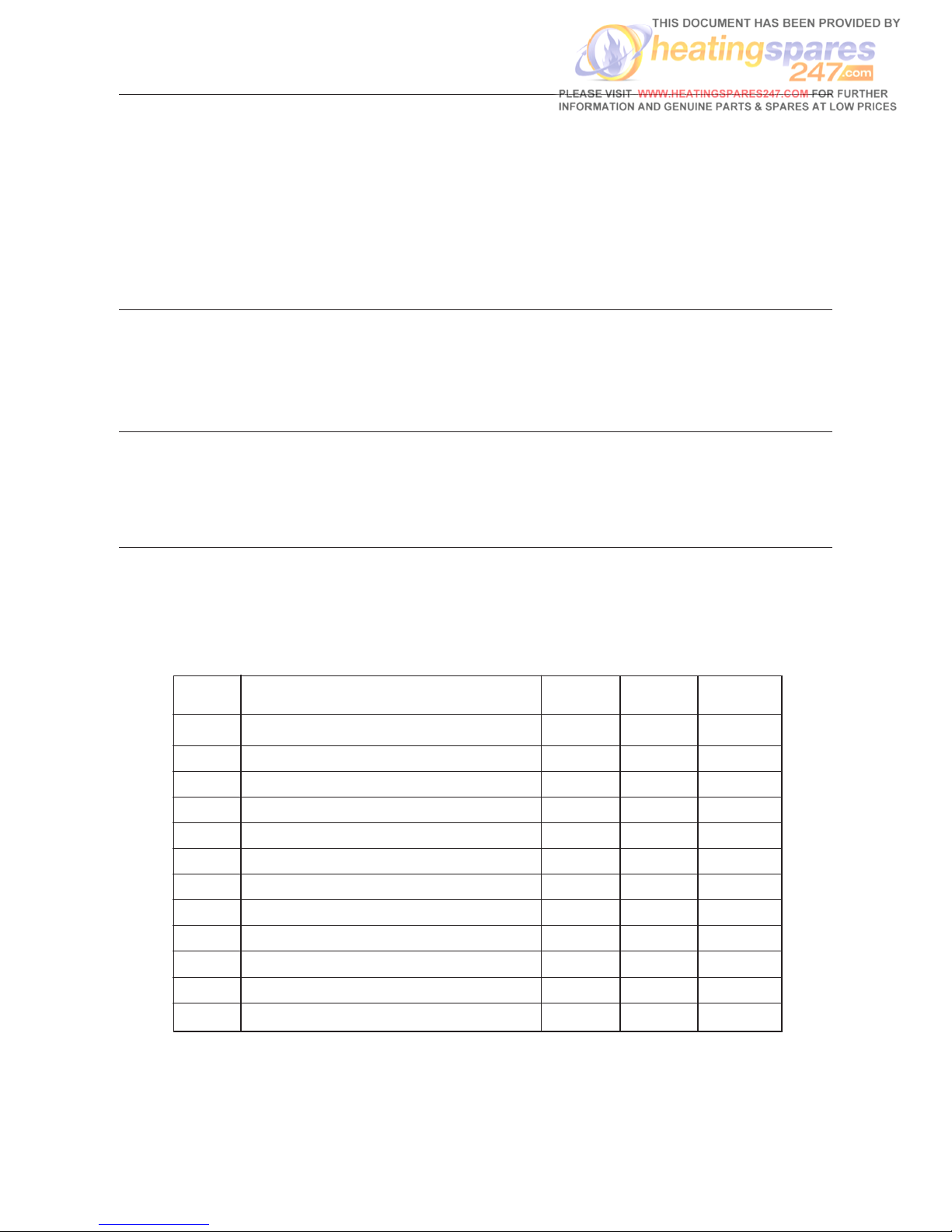
24
EuroTrader Boiler Parts
FAULT FINDING (Cont’d)
FAULT POSSIBLE CAUSE ACTION
MORNING START LOCK-OUT Faulty non-return valve or air leak Replace non-return valve and cure leak.
in two pipe system
Low voltage Check with local Electricity Board.
Combustion readings incorrect Check combustion under normal running
conditions and compare readings with
those given under ‘Burner Settings’.
Oil level in tank falling below burner Raise tank or fit a 2-pipe system.
DELAYED IGNITION - Nozzle partially blocked Replace nozzle
BURNER PULSATES ON Oil pressure too low Check and recommission
START UP Flue blocked or damaged Check and rectify
Fan slipping on shaft Check and retighten
Pump coupling loose or worn Check and replace
BURNER STARTS VIOLENTLY Delayed ignition Check electrode setting and adjust to
correct gap
Check electrodes for damage
Check H.T. leads for damage and positive
connection
Item Description No. Off 50/90 100/125
Boiler Body 1 222220 222240
Burner Assembly 1 221330 221350
Control Box Assembly 1 208256 208256
Limit Thermostat 1 206892 206892
Boiler Control Thermostat 1 206896 206896
Flue Cover Assembly 1 208803 208876
Baffle Top W.U. 3 208838 -
Baffle Top W.U. 2 - 208865
Baffle Bottom W.U. 1 208834 -
Baffle Bottom W.U. 6 - 208871
Flue Socket Plate 1 207772 207772
Gasket 1 204072 204072
Page 28
TRIANCO LIMITED
Thorncliffe, Chapeltown, Sheffield S35 2PH
T
el: Sheffield (0114) 257 2300
Fax: (0114) 257 1419
www.trianco.co.uk
© Trianco Limited, Copyright in this brochure and the drawings or illustrations contained in it is vested in Trianco Limited and neither
the brochure or any part thereof may be reproduced without prior written consent.
Trianco policy is one of continuous research and development. This may necessitate alterations to this specification.
Printed by WFO Press Ltd. (01709) 740078 February 2005 Item No.221685 Issue No. 5
 Loading...