

Page 1
AIR-TO-WATER
AIR SOURCE HEAT PUMP
S1800 S
USER, INSTALLATION,
COMMISSIONING & SERVICING
INSTRUCTIONS
Please read these instructions carefully before installing,
commissioning and using this appliance.
To be retained by the householder
1
Page 2

HEALTH AND SAFETY INFORMATION
i
INFORMATION FOR THE INSTALLER AND SERVICE ENGINEERS
Under the Consumer Protection Act 1987 and the Health and Safety at Work Act 1974, it is a requirement
to provide information on substances hazardous to health (COSHH Regulations 1998).
TR Engineering takes every reasonable care to ensure that these products are designed and constructed
to meet these general safety requirements, provided they are properly installed and used.
To fulfil this requirement, products are comprehensively tested and examined before despatch.
When working on the appliance, it is the responsibility of the user/engineer to ensure that any necessary
personal protective clothing or equipment is worn appropriate to parts which could be considered
hazardous or harmful.
This appliance may contain some of the items below:
Refrigerants
The appliance contains R407c refrigerant. The constituents of R407c are HFC’s R32, R125 and R134a,
all of which have low toxicity levels.
When handling, avoid inhalation and contact with the skin and eyes. Suitable personal protective
equipment must be worn (gloves, overalls, eye protection) and a comprehensive first-aid kit (containing
eye wash) should be easily accessible.
Site engineers should have a certificate of competence and should know and understand the properties
and hazards before handling liquid refrigerants.
When the appliance has come to the end of its life span, the equipment and refrigerant must be disposed
of in accordance with EU law, by an approved engineer.
Seek urgent medical attention if inhaled or ingested. Immediate cleansing of the affected areas
and medical attention if necessary should follow exposure to eyes and skin.
Insulation
Fibre insulation may be irritating to the skin, eyes, nose and throat. When handling, avoid
inhalation and contact with the eyes. Use disposable gloves, facemasks and eye protection.
After handling, wash hands and other exposed parts. When disposing, reduce dust with water
spray and ensure all parts are securely wrapped.
Glues, Sealants and Paints
Glues, sealants and paints are used in this appliance and present no known hazards when used
in the manner for which they are intended.
Page 3

ii
IMPORTANT SAFETY INFORMATION FOR THE END-USER
Installation of the appliance must only be carried out by persons with suitable engineering qualifications
Do not attempt to modify, repair or service the appliance yourself
Do not insert body parts or any other items into the air inlet or air outlet
Do not start or stop the unit by removing the power cable; always use the controls and switches provided
Ensure the appliance is protected from prolonged exposure to large quantities of water
Do not operate the unit or the programmer with wet fingers
Upon replacement of the fuse, ensure an adequate replacement is used (e.g. not fuse wire)
Keep the programmer unit out of reach of children
The electrical supply must be isolated during a heightened risk of lightning strikes
Do not attempt to move the appliance once installed; this must be carried out by a qualified engineer
Isolate the electrical supply to the appliance if an odour presents, or scorching is detected
Only use this appliance for the purpose intended
Ensure the area around the appliance is clean, well-ventilated and kept free of all obstructions
Do not keep items on top of the appliance or use it to support other appliances
Do not under any circumstances stand on the appliance
Isolate the electrical supply to the appliance if it is to be switched off for a period of more than two weeks
Drain the water from the water circuit if power to the unit is to be switched off during very cold weather
Periodically check the condition of any supports for deterioration
Do not wash the unit with water, alcohol, benzine, thinners, glass cleaner, polish or powders
During cleaning, isolate the electrical supply to the appliance
3
Page 4

The following information should be completed upon installation of the
iii
Installation Engineer’s Signature: ……………………………………………….
Company Name (if applicable): …………………………………………………..
Company Address: ……………………………………………………………..
……………………………………………………………..
……………………………………………………………..
Company Tel. No: ……………………………………………………………..
appliance, for householder reference:
Manufacturer’s Declaration of Conformity
European Directives Covered by this Declaration:
EN 55014-1 : 2000 (+A1:2001, A2:2002);
EN 55014-2: 1997 (+A1:2001);
EN 61000-3-2 : 2000 (+A2:2005);
EN 61000-3-3 : 1995 (+A1:2001);
EN 50366 : 2003;
EN 14511 : 2004 (parts 1 to 4)
EN 60335-2-40 : 2003 (+A11:2004) used in conjunction with
EN 60335-1:2002 (+A11:2004, A1:2004).
The Basis on Which Conformity is Being Declared
The products identified herein comply with the requirements of the
Low Voltage Directive (73/23/EEC) and the EMC Directive (89/336/EEC).
Samples of the product have been tested by the manufacturer
and a third-party certification body.
4
Page 5

CONTENTS
PAGE
Health & Safety (Materials) i
Important End-User Safety Information ii
Declaration of Conformity iii
Introduction 6
Operating Instructions 6
Setting the Clock/Timer 6 & 7
Non-timed Control 7
Setting the Water Temperature 7
Operating Parameter Display 8
Safety Cut-out Devices 8
Servicing 8
Simple Fault-Finding 9
Tips for Lowering Energy Usage 9
After-Sales Service Information 10
Technical Information 11
Dimensions & Clearances 11
Water Connection Dimensions 11
Mounting Dimensions 11
Technical Specification 12
Performance Data 12
Installation Instructions 13
Introduction 13
Regulations 13
Siting & Ventilation 13 & 14
Electrical 14
Internal Wiring Diagram 15
Health & Safety 16
Heating & Domestic Hot Water Systems 16
Flushing & Water Treatment 16
Mounting 16
Example System Schematics
17 & 18
Sealed System Components 19
System Filling 20
Commissioning 20
Servicing & Maintenance 20
Operating Parameters & Fault-Finding 21 & 22
Spares
23
Spares List 27
5
Page 6
INTRODUCTION
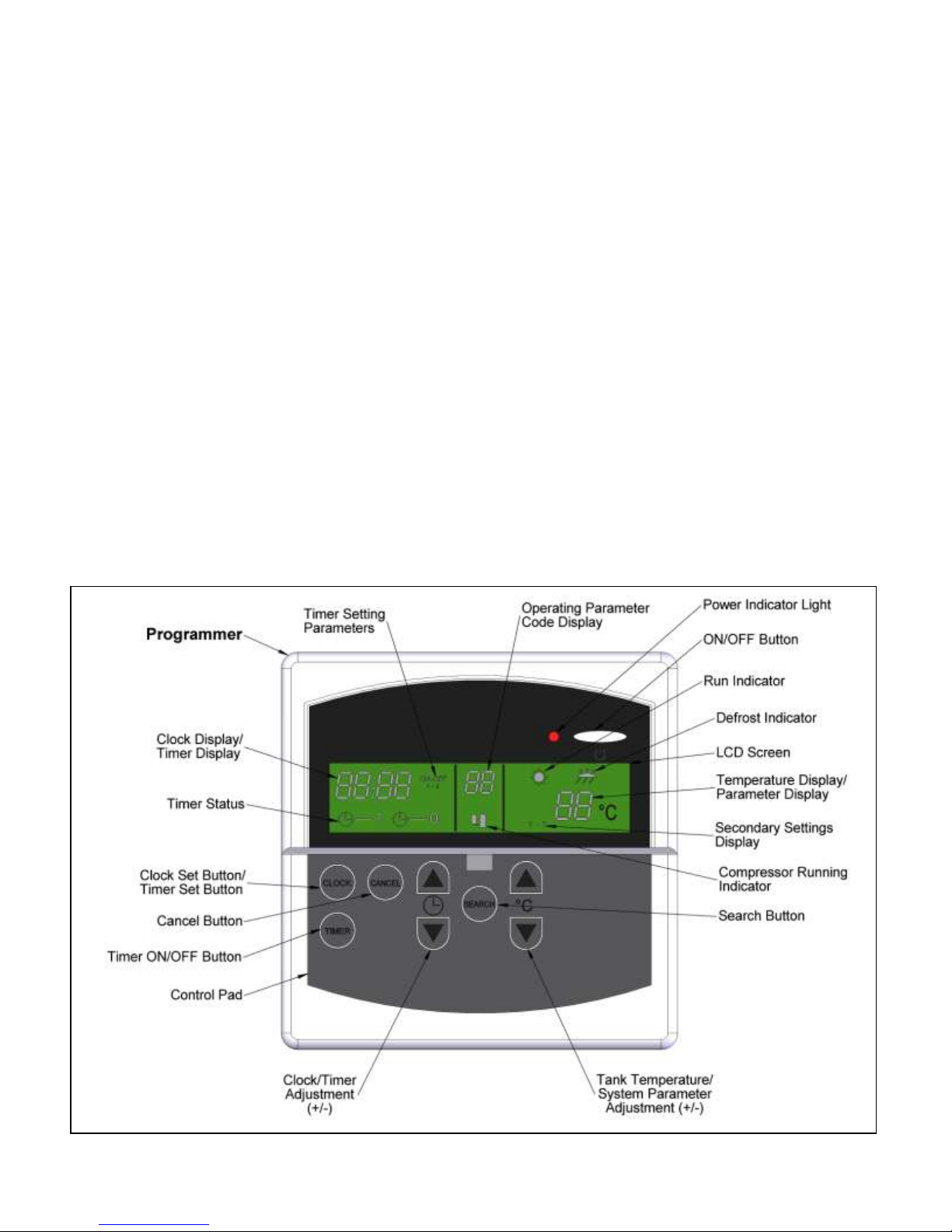
FIG 1
Please note, to assist TR Engineering in improving customer
service, it is important that the guarantee/registration card is
completed and returned.
The Activair is a single component unit air source heat
pump, designed to provide hot water or low-temperature
heating by extracting heat energy from the surrounding air.
The Activair has been designed and constructed to give
years of trouble-free service, and these instructions are
provided to assist you in obtaining the best performance with
the least trouble and cost.
OPERATING INSTRUCTIONS
The appliance is controlled via the remote programmer
included with the unit. This can be situated anywhere in the
property, enabling management of the settings without
having to access the main unit.
Before starting the appliance, ensure that it has been
installed in full accordance with these instructions and that
all necessary safety checks have been carried out.
The diagram below (fig. 1) shows the programmer layout with
the controls uncovered (lift off the protective flap).
SETTING THE CLOCK
Before starting the appliance, the clock should be set to enable
control of the heat pump via the timer.
Note: the appliance operates on a 24-hour clock only.
Ensuring the programmer is on standby (LCD screen will not be
illuminated), press the CLOCK button once. The first pair of
digits in the clock display will begin to flash. Press the CLOCK
ADJUSTMENT buttons (+/-) until the current hour is set.
Press the CLOCK button once more; the second pair of digits in
the clock display will begin to flash. Press the CLOCK
ADJUSTMENT buttons (+/-) until the minutes past the hour are
set.
To return to standby mode, repeatedly press the CLOCK button
until the current time is displayed in full.
6
Page 7
SETTING THE TIMER
Using the timer, it is possible to set two separate time periods
at which the appliance will operate.
Ensuring the programmer is on standby (LCD screen will not
be illuminated), press the CLOCK button three times. The first
pair of digits on the clock display will flash and the timer
settings display will read ‘ON’. The number immediately below
this will indicate that programme #1 is currently being
modified.
Press the TIMER ADJUSTMENT buttons (+/-) until the time is
set to the hour you wish the appliance to start.
Press the CLOCK button; the second pair of digits in the clock
display will begin to flash. Adjust in the same way to set the
minutes past the hour.
Press the CLOCK button and set the hour you wish the
appliance to cease operation. Press the CLOCK button once
more and set the minutes past the hour.
To return to standby mode, repeatedly press the CLOCK
button until the current time is displayed. To set a second
programme, instead press the CLOCK button once.
The first pair of digits on the clock display will flash and the
timer setting display will read ‘ON’. The number immediately
below this will indicate that programme #2 is currently being
modified.
Use the TIMER ADJUSTMENT buttons (+/-) as described
above to set the second programme. After setting the minutes
past the hour, press the CLOCK button once to return to
standby mode.
To activate the programme(s), press the TIMER ON/OFF
button once. The timer status display will read ‘1’.
The Activair should now cut in and out according to the times
set. The running indicator will display the SUN symbol
whenever the appliance is operating.
Please note that during the time periods at which the
appliance is set to operate, it will not do so constantly. When
the cylinder water temperature has reached the required level,
the heat pump will cease operation until the water has cooled
or has been used. During these periods, the SUN symbol will
flash in the running indicator display.
Please ensure that all other required parameters, such as
cylinder water temperature (see adjacent column), have been
set before operating the appliance.
To cease operation in this mode, press the TIMER ON/OFF
button once. The timer status display will read ‘0’ and the
appliance will return to non-timed control mode.
NON-TIMED CONTROL
It is possible to operate the appliance without using the timer
control. Ensure that the clock and all other required parameters
have been set before continuing.
Ensure the timer status display reads ‘0’ and press the ON/OFF
button at the top right of the programmer. The LCD display and
power indicator light will illuminate and the appliance will start.
The running indicator will display the SUN symbol whenever the
appliance is operating.
The appliance will now run until the required cylinder water
temperature is reached, at which time the SUN symbol will flash
in the running indicator display.
Please ensure that all other required parameters, such as
cylinder water temperature (see below), have been set before
operating the appliance.
To cease operation in this mode, press the ON/OFF button
once. The LCD screen and power indicator light will fade.
SETTING THE WATER TEMPERATURE
The appliance can be set to heat water between a range of
20°C and 55°C, depending upon your preference. The water
temperature can be adjusted at any time, whether the heat
pump is running or inactive.
To set the cylinder water temperature, press the
TEMPERATURE ADJUSTMENT buttons (+/-). The temperature
display will change accordingly, before returning to displaying
the current cylinder water temperature.
When the cylinder water temperature has reached the required
level, the appliance will cease to operate until the water in the
cylinder has been used or has cooled.
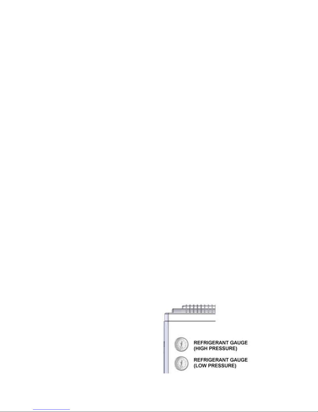
REFRIGERANT PRESSURE GAUGES
The appliance incorporates two refrigerant pressure gauges.
The lower gauge displays the refrigerant pressure at low levels
(pre-compression); the top gauge displays the refrigerant
pressure at high levels (post-compression). The default reading
for both when the Activair is idle is 9.6 bar (20°C ambient).
7
Page 8

OPERATING INSTRUCTIONS
(continued)
OPERATING PARAMETER DISPLAY
In certain circumstances, the unit may enter a temporary lock
out mode in order to maintain efficient operation. During such
times, a code will appear on the programmer display (fig. 1).
This is entirely normal and the unit will automatically resume
functioning once it has completed its reset cycle.
In the unlikely event the appliance does not resume operation,
full descriptions of the operating parameters and their causes
can be found on page 21.
FROST PROTECTION
As the appliance may be fitted externally to the property being
heated, the water in the system may be in danger of freezing
in very cold weather. As such, the Activair has frost protection
which will bring the heat pump on should the temperature drop
too low. However, to provide protection in the event of a power
outage, a suitable antifreeze should be added to the system.
DEFROST MODE
If the temperature is cold enough for ice to develop on the coil,
this may become clogged and cause the appliance to cease
operation. Should this occur, the unit will automatically enter
defrost mode. This will divert heat from the heating circuit back
to the coil until the ice has melted. The DEFROST symbol will
appear above the temperature display (see fig. 1) during such
times.
PRESSURE SWITCH
Should the refrigerant pressure within the appliance reach too
high a level, the unit will automatically switch off until the
pressure has been reduced, whereupon the unit will restart
automatically. Please note that the unit may take several
minutes to restart after the pressure switch has operated.
Refer to the operating parameter descriptions, page 21, for
further details.
AMBIENT TEMPERATURE CUTOUT
Should the ambient temperature around the appliance reach
too high a level, the unit will automatically switch off until the
temperature has been reduced, whereupon the unit will restart
automatically. Please note, that the unit may take several
minutes to restart after the cut-out has operated.
Refer to the operating parameter descriptions, page 21, for
further details.
COIL TEMPERATURE CUTOUT
Should the coil temperature reach too high a level, the unit will
automatically switch off until the temperature has been reduced,
whereupon the unit will restart automatically. Please note that
the unit may take several minutes to restart after the cut-out has
operated.
Refer to the operating parameter descriptions, page 21, for
further details.
COMPRESSOR OUTLET TEMPERATURE CUTOUT
Should the compressor outlet temperature reach too high a
level, the unit will automatically switch off until the temperature
has been reduced, whereupon the unit will restart automatically.
Please note that the unit may take several minutes to restart
after the cut-out has operated.
Refer to the operating parameter descriptions, page 21, for
further details.
SHUTTING DOWN FOR LONG PERIODS
If power to the heat pump is shut down for a long period during
very cold weather, it is advisable to completely drain the system.
However, too frequent draining of the system should be
avoided, especially in hard water areas, as this could lead to the
build-up of scale in any heating circuit.
SERVICING
While it is not necessary to carry out an annual service on the
appliance, regular inspections may be required, depending upon
where the unit is sited. Full details can be found on page 20.
8
Page 9

SIMPLE FAULT-FINDING
TIPS FOR IMPROVING PERFORMANCE AND EFFICIENCY
1) Unit maintenance has a dramatic impact upon system performance and service life. Ensure regular inspections are
carried out over the lifetime of the appliance. Dirty coils and fans reduce airflow through the system, resulting in
decreased performance. Regular checks should be carried out to ensure the cleanliness of these components.
2) Programme the appliance to operate at times when the surrounding ambient temperature is at its highest (e.g. noon).
A thermal store may be employed to allow the retention of hot water at this time for later use.
3) If installed externally to the property being heated, the unit should be protected from high winds, as this can lead to
reduced airflow and efficiency, and also cause frost problems; though avoid siting in areas where the airflow is too
restricted, resulting in recirculation of air over the coil.
4) Well-insulate the pipework to and from the appliance to retain as much heat as possible.
5) Where possible, subscribe to economy electricity tariffs (contact your electricity supplier for more information).
6) Lower temperature settings will reduce the amount of energy consumed by the unit.
If the appliance fails to start for no apparent reason, carry out
the following checks before referring to the operating parameter
and fault-finding guide (page 22)
engineer:
1. The unit may be running through a process to clear an
operating parameter condition. In most cases, this will be
cleared automatically, though if it persists, check the
programmer display (fig. 1) for an operating parameter
number. Refer to the guide on page 21 for full descriptions
and remedies.
2. Ensure there is a current ‘heat demand’ from the
programmer. Ensure the programmer clock and timer
controls have been set in accordance with the instructions
on pages 6/7 or that it is switched on (if in non-timed mode).
3. Check for failure in the electrical supply.
4. Check for a blown fuse. If the fuse has blown and the
replacement also fails, switch off the mains electrical supply
to the appliance and contact your service engineer.
5. Check the circuit breaker (if fitted). If this has tripped, reset
and restart the appliance. If the circuit breaker trips for a
second time soon after, switch off the mains electrical supply
to the appliance and contact your service engineer.
Note: if the appliance has been shut down due to a failure of the
power supply, the programmer contains a battery backup which
will allow the preservation of all settings and timings.
If the appliance is operating, but the water temperature is lower
than expected:
1. Check that all isolation valves are fully open.
2. Check the water temperature setting is not too low. This
can be increased by following the instructions on page 7.
, or calling your service
3. Check that the vents on the back of the unit and the coil
have not become blocked, impeding the air flow.
4. Check the unit has not entered defrost mode (the DEFROST
symbol will appear above the temperature display – see fig.
1). Should this occur, the heat output from the appliance will
be diverted to the coil, until any ice build-up has been
removed.
5. Ensure there is no air trapped in either the Activair or the
heating/hot water system (page 20).
If sounds are heard from the appliance which sound like the
passage of water, this is merely the normal movement of the
refrigerant within the unit.
If there is power to the appliance and the programmer is
providing a 'heat demand’ to the unit, yet the unit has not
entered running mode (the SUN symbol has not appeared
above the temperature display), it may be that one of the safety
cut-outs (see page 8) has operated. These will typically take
several minutes to clear before the unit restarts.
Other Checks
Ensure the default system settings have not been altered.
These are accessed by holding in the SEARCH button for five
seconds when the programmer is switched off. These are
factory-set and should not require adjustment.
Setting 1 - Factory-set at 26.
Setting 2 - Factory-set at 18.
Setting 3 - Factory-set at 14.
These settings should not be altered from the above without the
express permission of Trianco.
If for some reason the settings do not match the figures given
above, alteration is made via the TEMPERATURE
ADJUSTMENT buttons (+/-).
9
Page 10

Appliance Serial No.: ___________________
Cust. ID No.: ______________________
Installation Date: ____/____/____
Corrosion Inhibitor Fitted: Yes: ___ No: ___
SERVICE CENTRE AND TECHNICAL SUPPORT
Tel: 0114 257 2300
Fax: 0114 257 1419
Hours of Business
Monday – Thursday: 8:30am – 17:00pm
Friday: 8:30am – 14:30pm
AFTER-SALES SERVICE INFORMATION
A qualified field service engineer is available to
attend a breakdown or manufacturing fault occurring
while the appliance is under guarantee.
The appliance must be made available for service
during normal working hours, Monday to Friday.
Please note, upon attendance by a
TR Engineering field service engineer, a charge
will be made on-site where:
The field service engineer finds no fault with the
appliance
The cause of a breakdown is due to other parts
of the system not manufactured by
TR Engineering
The cause of the breakdown is due to incorrectly
fitted spare parts, or third-party spares not
designed for specific use with the appliance
The appliance has not been correctly installed
as recommended in these instructions, or by
unqualified persons
The breakdown occurs outside the guarantee
period
The appliance has not been maintained correctly
The breakdown occurs due to use of the
appliance not sanctioned by these instructions
The breakdown occurs as a direct result of
unauthorised third-party work on the appliance
Important:
Invoices for attendance and repair work carried
out on this appliance by any third party will not
be accepted unless authorised in advance by the
TR Engineering service centre.
TECHNICAL ASSISTANCE
A team of trained technical advisors are available to
discuss any problem with the appliance which may
occur. In many cases, the problem may be solved
over the telephone, eliminating the need for a service
visit.
HOW TO REPORT A FAULT
Step 1:
Contact your installer or service engineer, who
should thoroughly check all recent work before the
attendance of our field service engineer is requested.
Step 2:
Contact the TR Engineering service centre for
assistance. Please make a note of any operating
parameter codes, which appear, on the programmer
display before making contact.
If your own installer/service engineer is unavailable,
contact the TR Engineering service centre. Please be
aware that a charge may be made for any visit not
covered by the appliance guarantee.
Before contacting either the TR Engineering
service centre or the technical advice line, please
have the following information ready:
1) Appliance serial number or your unique
customer identification number (issued upon
registration of the appliance with
2) TR Engineering)
3) Description of fault, including any operating
parameter code which may be displayed on the
programmer
4) Date of installation
10
Page 11
TECHNICAL INFORMATION
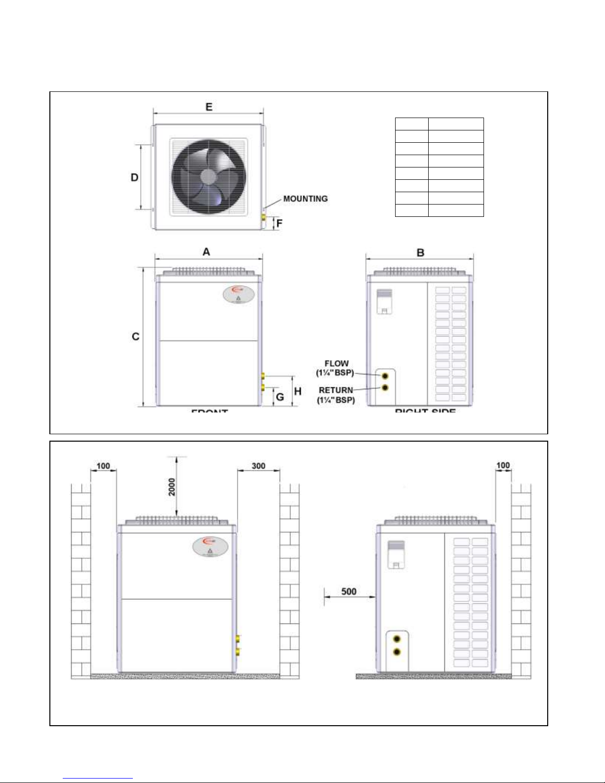
FIG 3 - CLEARANCES
FRONT VIEW
SIDE VIEW
A
748 B 748
C
1030
D
619 E 753
F
72.5
G
130 H 285
ALL DIMENSIONS IN mm
FIG 2 – OVERALL DIMENSIONS
11
Page 12
TECHNICAL SPECIFICATION
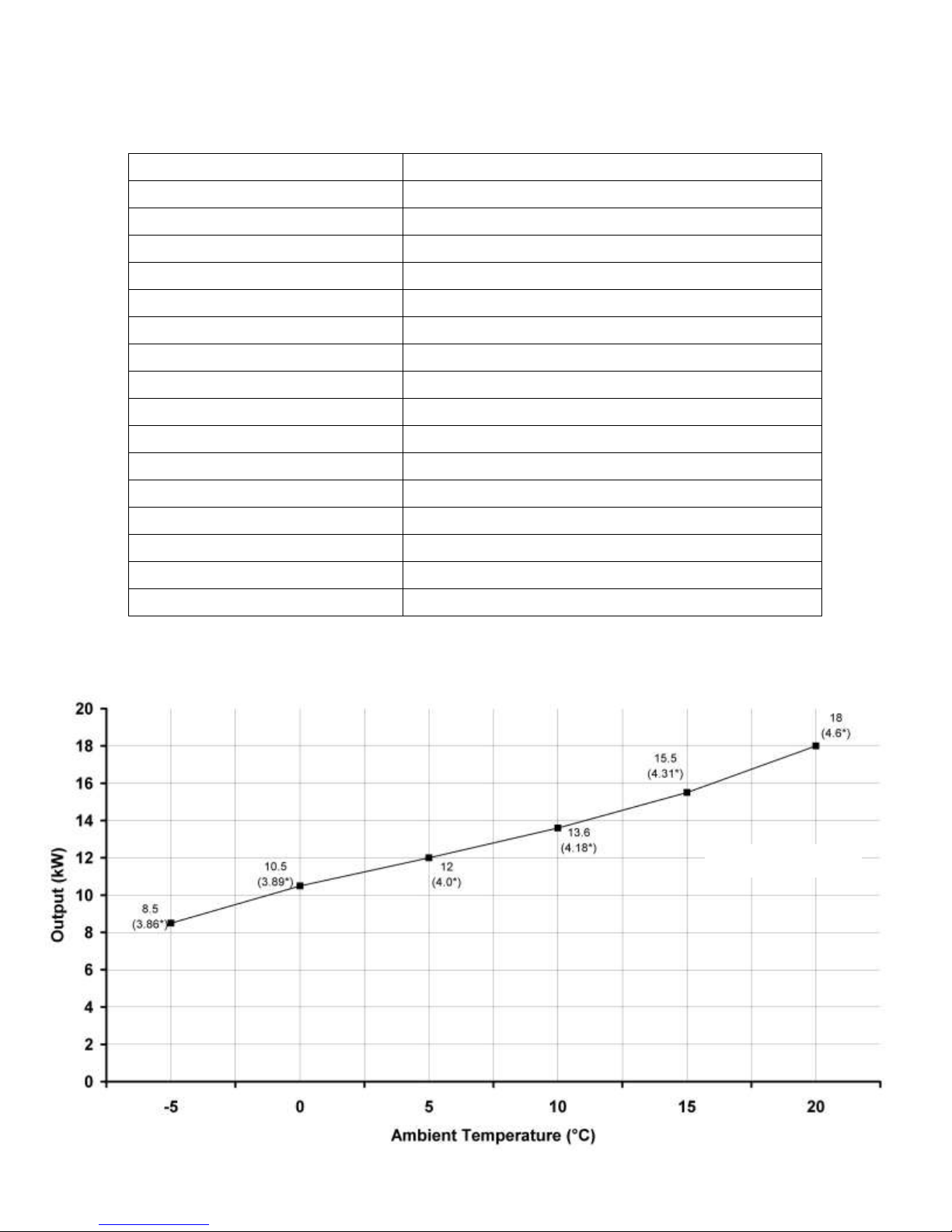
Output / Ambient
See graph below
Max. Input Power
6.5kW
Max. Input Current
29 amp
Cable Size
6mm
Required Flow Rate (primary water)
70 litres/min
Weight (empty)
150kg
Noise Level
60 dB(A)
Min. Water Output Temperature
20°C
Max. Water Output Temperature
55°C
Power Supply
Working Ambient Temperature Range
Flow & Return Connections
Refrigerant
Refrigerant Pressure (20°C ambient)
Electrical Shock Protection
Water Protection
Casing Finish
*Denotes input
HEATING PERFORMANCE
230V - 50Hz Fused at 32 amp
-5°C to 43°C
1¼” BSP
R407c (4.2kg)
9.6 bar (idle)
1
IPX4
White
12
Page 13

INSTALLATION
CAUTION: Uneven Load
INTRODUCTION
The Activair air source heat pump must be installed in full
accordance with these instructions and all relevant
standards.
Installation must be carried out by a fully qualified engineer.
All specialised work (e.g. electrical and handling of
refrigerants), must be carried out by suitably qualified
individuals.
All heat pumps are provided charged with refrigerant and are
fully tested and programmed, requiring only connection to a
suitable wet system, a suitable electrical supply and the
setting of the clock parameters and required water
temperature.
The Activair operates best with well-insulated buildings
which comply with current Building Regulations (Part L).
The unit utilises R407c refrigerant.
REGULATIONS
These installation notes are for guidance only, and should
be superseded by any national or local regulations which
may apply.
Installation of the appliance must comply with BS 15450
Design of Heat Pump Heating Systems, and all other
relevant British Standards and Regulations, Building
Regulations, current I.E.E. Regulations, and the Local Water
Undertakings Bylaws.
HEALTH AND SAFETY
Health and Safety at Work Act
The installer should be aware of his responsibilities under
the Act and provide, where necessary, appropriate
protection for all persons carrying out the installation
Lifting
The appliance may require two persons, or specialised lifting
equipment, to lift into position. Ensure all lifting equipment is
fully approved and checked for safety before use.
Do not under any circumstances stand on the appliance.
SITING & VENTILATION
Important note: if the unit has been moved significantly from an
upright position prior to installation, it must be left standing for at
least 24 hours before use.
The Activair can be fitted either internally or externally to the
property being heated.
The appliance must be installed in a clean, well-ventilated area
which is free of all obstructions. Please ensure enough space is
left around the unit to enable access for routine inspections.
See page 11, fig. 3 for appropriate clearance dimensions.
Failure to ensure adequate clearances may hinder correct and
efficient operation of the unit.
Please note that the appliance may have to be moved in order
to gain access to some of the serviceable items from the rear.
The appliance should not be boxed-in, as the movement of free
air is vital to the correct operation of the appliance.
Do not install the appliance in areas which have a potential for
gas leakage or with a high concentration of salts, oils, soot and
sulphur.
Do not install the appliance on a moving vehicle (e.g. a ship or
barge).
If the unit is installed outside, ensure it is adequately protected
from prolonged exposure to large quantities of water. Note: the
unit is designed to operate normally in wet conditions.
It is preferable, though not essential, that the unit is sited in a
position that receives maximum sunlight.
The appliance controls should always be sited within the
property.
The appliance should only be installed on a sturdy base, which
is level and capable of supporting the installed weight of the
unit, including its full water content. The base should be firm
enough to prevent vibration.
The use of vibration pads is recommended to prevent excess
vibration and noise transmission.
To obtain the best performance from the S1800S
it is recommended that the unit be sited externally
to the property being heated.
Do not site above doorways or other openings.
13
Page 14

SITING AND VENTILATION
(continued)
Do not install the appliance within 1000mm of television, radio
or stereo equipment.
The appliance should not be installed where it will be exposed
to unusually high wind speeds.
Sound Levels
Whilst the low sound levels of the appliance makes it suitable
for siting externally and internally, the following factors should
be taken into consideration before installation:
a) Some people are particularly sensitive to low noise levels
– discuss with the end-user and site in a place where the
least nuisance would be caused to neighbours. If in doubt,
contact the local council. If necessary, construct an
acoustic barrier.
b) Small rooms tend to amplify noise, particularly if the room
construction is hollow or the surface tiled.
MOUNTING
The appliance should be screwed firmly to a sturdy base via
the mounting feet on the underside of the unit. The base
should be level and capable of supporting the installed weight
of the unit, including its full water content. The base should be
firm enough to prevent vibration.
INTERNAL INSTALLATION
Ensure adequate clearances are in place to enable the heat
pump to pass through any entrances (see page 11, fig 2 for
unit dimensions). Ensure adequate provisions are in place for
maintenance and potential removal of the heat pump at a
future date. The room must be well insulated.
Ventilation/Air Flow
Inadequate airflow over the coil may result in reduced
performance. The airflow requirement is 1175 cubic feet per
minute. If adequate airflow cannot be achieved, ventilation
from the outside may be required.
PUMP CHOICE AND FLOW RATE
Please note that a 15/50 or 15/60 pump will not
be suitable to achive the minimum flow rate required.
Failure to achive the flow rate can cause serious
damage to the appliance and will invalidate the warranty.
(see page 12 for required flow rate)
ELECTRICAL
230V single-phase 50Hz (fused 32 amp).
Electrical work should be carried out in accordance with BS
7671:2001, current I.E.E. regulations and any local
regulations which may apply, by a qualified electrical
engineer.
Important: isolate the electrical supply before accessing the
inside of the appliance.
This appliance must be earthed and the earth cable must be of
a greater length than the current-carrying conductor cables (i.e.
live and neutral supply cables).
Connection to the appliance should be hard-wired to the
consumer unit.
The minimum supply cable size is 6mm
In the event of a fault after installation, the electrical system should
be thoroughly checked for fuse failure, short circuits, incorrect
polarity, resistance to earth, and earth continuity.
In certain areas of the country, where there is a known risk of
high or low voltage fluctuations, the appliance should be
prevented from starting by the use of a voltage-sensitive device
if the voltage drops or increases sufficiently to endanger the
installation.
The programmer is connected to the unit via the plug supplied
with the appliance.
If the supply cord is damaged, it must be replaced by the
manufacturer, its service agent or similar, for one of the same
specification as that fitted.
fig. 4
See
PUMP AND WATER FLOW SWITCH WIRING
The pump should be wired into the appliance as shown on the
wiring diagram opposite (into terminals 4 (live) and N (neutral)).
A water flow switch can be fitted to terminals SL and PCOM.
Should a water flow switch not be fitted, these must be linked.
BACKUP WIRING
A backup system, such as an inline boiler or an immersion
heater, can be controlled by the Activair by wiring controls into
terminals 3 (live) and N (neutral). This will cause the backup to
operate should the ambient temperature around the Activair
drop to 0°C or below. Alternatively, a separate low-temperature
thermostat can be used.
NOTE: Any backup should have its own independent power
supply. The Activair is providing a switched live only.
for internal wiring details.
14
Page 15
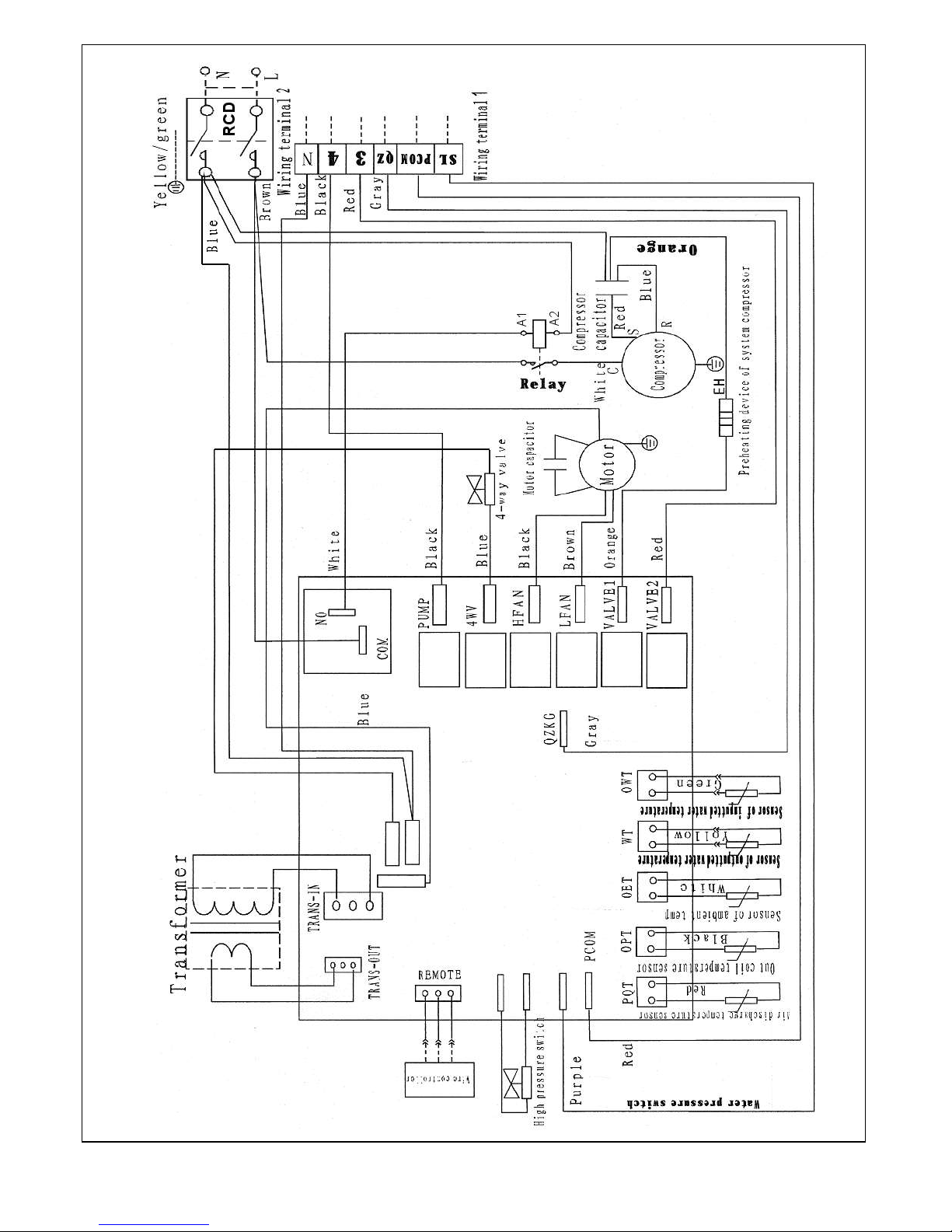
FIG 4 – INTERNAL WIRING DIAGRAM
15
Page 16

INSTALLATION (continued)
DOMESTIC HOT WATER AND HEATING SYSTEMS
Heating systems must be installed in accordance with HVCA
Codes of Practice and BS 5449 Part 1.
The flow and return water connections are made on the right
side of the unit. Flexible connectors must be fitted to the flow
and return tappings to prevent vibration to the pipework. Refer
to fig. 2 for pipework dimensions.
Isolation valves must be fitted on the flow and return pipework
close to the appliance, for ease of disconnection and servicing.
On sealed systems, a 3 bar pressure relief valve must be
situated between the heat pump and the first isolation valve on
the return side. The system should be fitted with an automatic
air vent.
Some typical DHW and central heating system schematics are
shown on figs. 5-10 overleaf. See page 20 for filling
instructions.
It is strongly recommended that 35mm diameter pipework
is used. This will help to
water through the system.
All pipework should be insulated in accordance with the relevant
Building Regulations. All pipework external to the property
should be kept to a minimum, and must be insulated.
ensure an appropriate flow of
FLUSHING AND WATER TREATMENT
The performance of the appliance could be impaired by system
debris or the effects of corrosion. New systems must be
thoroughly flushed to remove metal filings, solder, machining
oils and any other fluxes or greases before connecting the unit.
When fitting the appliance to an existing system, it is advisable
to clean the system by using an appropriate flushing and
descaling agent. Refer to BS 7593 [1992] for guidance. System
additives – antifreeze, corrosion inhibitors and all flushing
agents/descalers should be suitable for this type of appliance.
Always refer to manufacturers' instructions.
Failure to flush and add inhibitors to the system may
invalidate the appliance warranty. The appliance must not
be run without water in the system.
HEATING PERFORMANCE
The Activair provides hot water and heating by extracting
ambient heat energy from the surrounding air. Therefore, in
lower temperature conditions, the output of the unit will be
reduced. All hot water system, cylinder, central heating and
underfloor heating sizing calculations must take this into
account. A chart of Activair heat outputs at various ambient air
temperatures can be found on page 12. Should a backup
system be required, such as an immersion heater or inline
boiler, this can be controlled by the Activair. See page 14 for
wiring details.
CYLINDER AND UNIT SIZING
The size of the cylinder to be used in conjunction with the
appliance is determined by the type of cylinder fitted. Modern
cylinders will provide details on heat-up times based upon a
particular heat input. A cylinder sized to the requirements of the
end user can then be selected.
Alternatively, approximate cylinder recovery times can be
calculated using the following formula:
(Cylinder size (litres) x 1.16 x required temperature rise)
/ 1000
This will return the kW input required for the cylinder to fully heat
up in one hour.
Example
The following example calculation is based upon a 100-litre
cylinder and a required temperature rise of 40°C (from 15°C to
55°C):
100 x 1.16 = 116
116 x 40 = 4640
4640 / 1000 = 4.64kW
This is the kW input required to heat the cylinder in one hour.
Therefore, an Activair unit running at a 12kW output would heat
the cylinder in 23 minutes.
Please note that some differences may apply depending upon
the age and type of cylinder used.
CENTRAL HEATING
If required, the Activair can provide low-temperature comfort
heating. The maximum water temperature from the appliance is
55°C. As such, radiators should be sized approximately 33%
larger than would otherwise be recommended for more
conventional forms of heating. Alternatively, instruct the end
user to programme the heating to come on earlier than with
conventional heating, or use double-panelled radiators.
The use of a thermal store (buffer tank) is
required in order to maintain correct water flow rates. The
store may be a direct or indirect cylinder. See figs 5-10 for
some example system schematics.
UNDERFLOOR HEATING
The use of a thermal store is required in order to properly
regulate the flow of water through the system. It will also help to
prevent short cycling, improving the efficiency of the unit. The
store may be a direct or indirect cylinder. See figs 5-10 for
some example system schematics. See page 19 for buffer tank
sizing directions.
16
Page 17
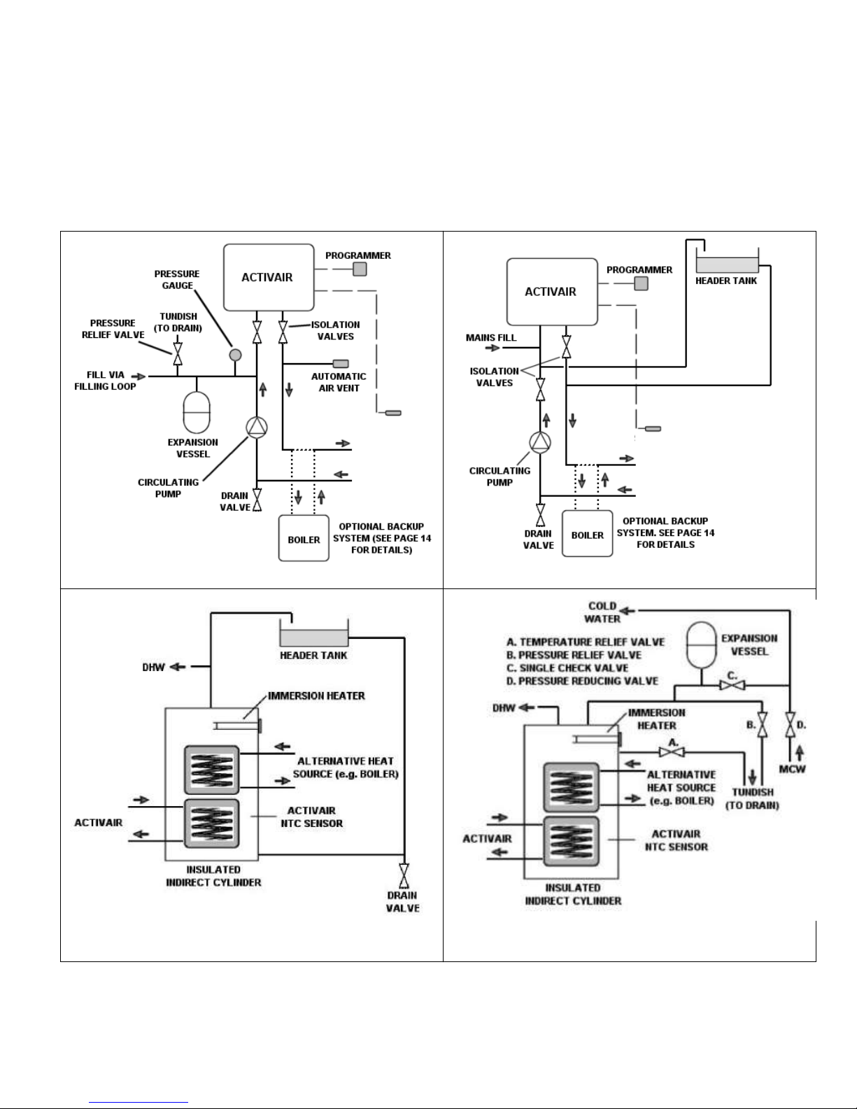
FIG 5 – ACTIVAIR SIDE (SEALED SYSTEM)
FIG 6 – ACTIVAIR SIDE (OPEN VENT SYSTEM)
FIG 7 – DHW CYLINDER (OPEN VENT SYSTEM)
FIG 8 – DHW CYLINDER (SEALED SYSTEM)
SENSOR IN
BUFFER TANK
BUFFER
TANK
SENSOR IN
BUFFER TANK
BUFFER
TANK
SYSTEM SCHEMATICS
The Activair is suitable for connection to standard sealed systems and open vent systems. The following example schematics are for
reference only. All systems must be installed in compliance with current Building Regulations and any local directives which may apply.
Note: a circulating pump is not included within the Activair unit.
17
Page 18
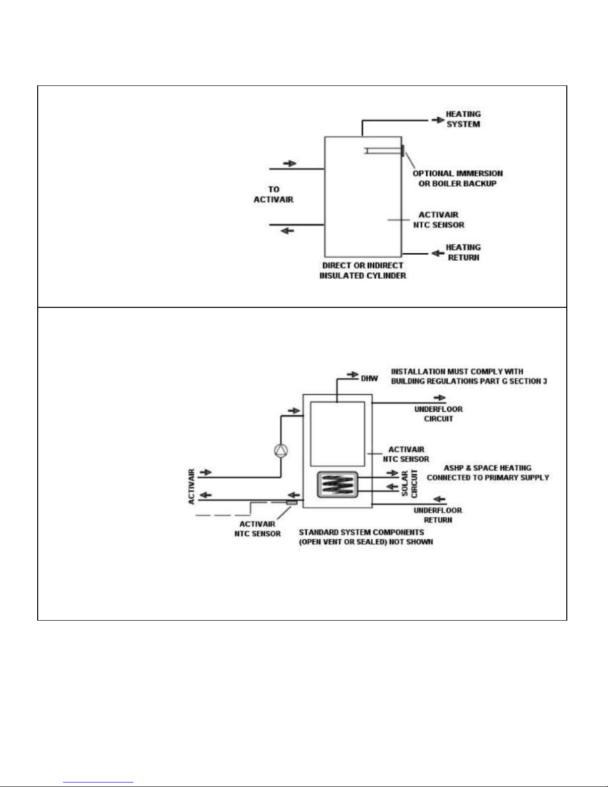
SYSTEM SCHEMATICS (cont.)
BUFFER TANK FOR STANDARD OR
UNDERFLOOR HEATING CIRCUITS
FIG 9
FIG 10 –
DHW & HTG VIA
TANK-IN-TANK WITH
SOLAR COIL
18
Page 19

CYLINDER SENSOR
A submersible cylinder sensor is supplied packed with the
appliance. The sensor MUST be fitted into the cylinder or buffer
tank approximately 1/3 up from the base of the tank or cylinder,
into a wet pocket if available. If using a dry pocket please
ensure heat sink paste is used to give good heat transfer. A
compatible NTC-type sensor may be used in place of the one
supplied with the Activair. Under no circumstances should the
system be run without a sensor fitted in the correct position.
DRAINAGE / DEFROST
In the event that the appliance enters defrost mode (indicated by
the appearance of the DEFROST symbol on the programmer
display – see fig. 1), heat generated by the unit will divert from
the heating circuit back to the coil until any ice has melted. In
such circumstances, the water formed as a by-product will
collect in the bottom of the unit. It is also possible that water will
be sucked or blown into the appliance during heavy rain.
The water will drain from holes in the base of the Activair. If the
unit is installed outside, provision should be made to drain this
water to a soakaway; if the unit is installed indoors, a collection
tray should be used, which can either be emptied periodically or
piped to a drain or soakaway.
SEALED SYSTEMS
Expansion Vessel
Failure to ensure the correct sized expansion vessel can result
in the premature failure of the expansion vessel and associated
system components.
Safety Valves
All pressure relief valves fitted to the heat pump side of the
system should be rated at 3 bar.
BUFFER TANK SIZING
In accordance with BS EN 15450, the minimum size of the
buffer tank should be 12 times the expected kW output of the
Activair. The maximum size of the buffer tank is 35 times the
expected kW output of the Activair.
LEGIONELLA
When the unit is connected to a domestic hot water
cylinder, it is necessary to take steps to combat potential
legionella infection. This can be achieved by connecting
a secondary heat source to the cylinder, which should be
programmed to activate once per week in order to briefly
take the water temperature to 65°C or above.
19
Page 20
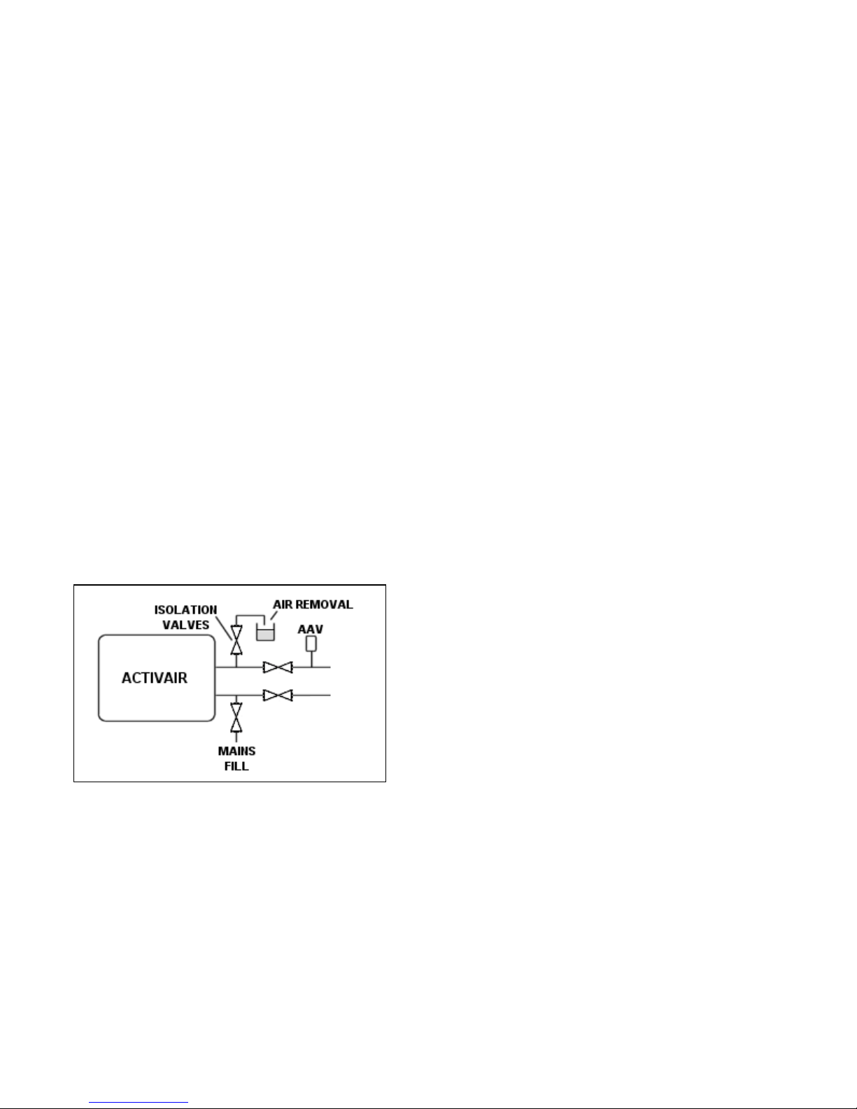
FIG 11
INSTALLATION (continued)
SYSTEM FILLING
Sealed Systems
Before filling the system, ensure that all fittings and joints have
been made. Thoroughly flush out the system to remove any
swarf and residue from the pipework and associated
components.
Fill the system to the pressure required (recommended 1 bar),
via an approved filling loop. Ensure all air has been vented from
the system before operating the appliance.
Open Vent Systems
Fill via mains pressure to flush air out of the system (see fig. 11
below for further details). There must be no permanent
connection between the appliance and the mains water supply.
Air Removal
If the air is not fully removed from the system, a lockout will
occur within the unit (operating parameter 8), causing it to cease
operation. To remove excess air, open the isolation valves to
the heating/hot water system and fill using one of the above
methods until the air has been removed via the automatic air
vent. Should air remain within the Activair, close the isolation
valves to the system and use mains pressure to expell air as
shown in fig. 11 below.
COMMISSIONING
After the safe installation of the heat pump in full accordance
with these instructions, it is important that the unit is
commissioned to ensure reliable operation:
1) Fill the system, in accordance with the filling guide above.
2) Switch power on to the unit and set the water temperature
on the programmer to 40°C (see operating instructions,
page 7).
3) The SUN symbol will appear at the top-right of the
programmer display (fig 1) as the unit operates. Run the
heat pump until the water temperature has reached 40°C.
The SUN symbol will flash when the water reaches this
temperature and the unit will cease operation.
4) Press and release the search button and check readings
1 to 4. The temperature diffrerence between 1 and 4
should be no more than 25 deg C. If the difference is
higher check for impaired water flow.
5) Explain all system controls and the maintenance procedure
(below) to the end-user. Make adjustments to the
programmer settings as requested.
SERVICING & MAINTENANCE
While it is not necessary to carry out an annual service on the
appliance, regular inspections may be required, depending upon
where the unit is sited.
Note: Isolate the electrical supply to the appliance before
accessing the interior of the unit.
INTERNAL INSTALLATION
A visual inspection of the fan and coil should be made once per
year. Clean as often as is necessary (e.g. when dirt build-up is
visible) and remove any obstructions.
Ensure the supporting base remains stable and capable of
supporting the full weight of the appliance, including its water
content.
EXTERNAL INSTALLATION
Every Three Months
Visually inspect the appliance, and remove any leaves, plant life
or debris from around or inside the unit.
Every Twelve Months
A visual inspection should be made of the fan and coil. Clean as
often as is necessary (e.g. when dirt build-up is visible) and
remove any obstructions.
Ensure the supporting base remains stable and capable of
supporting the full weight of the appliance, including its water
content.
If the appliance is installed in a coastal area, the periodic
removal of salt may be required from the coil.
Panels
Periodically clean the panels by wiping with a damp cloth. Do
not use alcohol, benzine, thinners, glass cleaner, household
polish or powders. It may be appropriate to apply a protective
wax to the casings, especially in coastal areas.
20
Page 21

OPERATING PARAMETER CODES
Code
Description
Cause
Solution
01
Water cylinder temperature cut-out
activated
Sensor disconnected
Short circuit
Faulty sensor
Reconnect sensor to PCB (see internal
wiring diagram, fig. 4)
Check connection between sensor and
appliance.
Check sensor for correct operation.
Repair or replace as necessary
02
Compressor sensor cut-out activated
Sensor disconnected
Short circuit
Faulty sensor
Reconnect sensor to PCB (see internal
wiring diagram, fig. 4)
Check connection between sensor and
appliance
Check sensor for correct operation.
Repair or replace as necessary
03
Compressor outlet temperature cycle
When compressor outlet temperature
has returned to normal, unit will
automatically reset
05
Ambient temperature cycle
When ambient temperature has returned
to normal levels, unit will automatically
reset
06
Coil temperature cycle
Coil temperature too high
When coil temperature has returned to
normal levels, unit will automatically
reset
07
Programmer cut-out activated
Short circuit
Faulty programmer
Check wiring and settings. Repair or
replace as necessary
Repair or replace as necessary
08
Refrigerant pressure cut-out #1
No water in appliance
Air Lock
Impaired Water Flow
Cylinder sensor detecting incorrect
temperature
Refill system with water (refer to filling
guide, page 20). Unit will automatically
reset
Flush air and refill system with water
(refer to filling guide, page 20). Unit will
automatically reset
Ensure circulating pump is operating
correctly, that all pipework is clear and
free of obstruction, and is correctly sized
for the installation
Ensure cylinder sensor is positioned
correctly. Ensure
cylinder flow and return are correctly
piped (refer to system schematics,
pages 17-18)
09
Refrigerant pressure cut-out #2
Leak on refrigerant system
Operating parameter 8 activated
Repair leak, replace refrigerant (note:
only to be carried out by a fully-qualified
engineer)
See remedies for operating parameter 8
In certain circumstances, the unit will display a code on the programmer screen (fig. 1). A description of these codes and their
causes can be found in the chart below:
Compressor outlet temperature too
high
Ambient temperature too high
21
Page 22

FAULT-FINDING
If the appliance fails to start for no apparent reason and an
operating parameter code (page 21) is not displayed on the
programmer, carry out the following checks:
1. Check for failure in the electrical supply.
2. Check for a blown fuse.
3. Check the circuit breaker (if fitted). If this has tripped reset
and restart the appliance.
4. Ensure there is a current ‘heat demand’ from the
programmer. Ensure the programmer clock and timer
controls have been set in accordance with the instructions
on pages 6/7 or that it is switched on (if in non-timed
mode).
5. Check the programmer settings by pressing the SEARCH
button for five seconds.
Setting 1 - set at 26.
Setting 2 - set at 18.
Setting 3 - set at 14.
These are factory-set and should not in normal
circumstances have been altered. If for some reason the
settings do not match the figures above, alteration is made
via the TEMPERATURE ADJUSTMENT buttons (+/-).
Note: if the appliance has been shut down due to a failure of the
power supply, the programmer contains a battery backup, which
will allow the preservation of all settings and timings.
If the appliance is operating, but the water temperature is lower
than expected:
1. Check that all isolation valves are fully open.
2. Check the water temperature setting is not too low. This
can be increased by following the instructions on page 7.
3. Check that the vents on the back of the unit and the coil
have not become blocked, impeding the air flow.
4. Check the unit has not entered defrost mode (the
DEFROST symbol will appear above the temperature
display see fig. 1). Should this occur, the heat output from
the appliance will be diverted to the coil, until any ice buildup has been removed.
5. Ensure there is no air trapped in either the Activair or the
heating/hot water system.
If sounds are heard from the appliance, which sound like the
passage of water, this is merely the normal movement of the
refrigerant within the unit.
If there is power to the appliance and the programmer is
providing a 'heat demand’ to the unit, yet the unit has not
entered running mode (the SUN symbol has not appeared
above the temperature display), it may be that one of the safety
cut-outs (see page 8) has operated. These will typically take
several minutes to clear before the unit restarts.
22
Page 23
SPARES
Item
Description
Part Number
Qty
1
PCB
224524
1
2
Programmer
224501
1
3
Compressor
224526
1
4
Compressor Capacitor
224530
1
5
Fan Motor
224528
1
6
Fan Motor Capacitor
224539
1
7
Transformer
224506
1
8
Relay
224542
1
9
Relay Cable
1
10
NTC Sensor
1
11
Fan Blades
1
12
Auxiliary Starter
1
13
Programmer Extension Cable
1
14
NTC Sensor PCB Adaptor Cable
1
15
Ambient Temperature Sensor
1
16
Heat Exchanger Temperature Sensor
1
17
Exhaust Temperature Sensor
1
18
NTC Sensor Extension Cable
1
224543
224508
224545
224520
224535
224531
224546
224547
224548
224536
23
23
Page 24

TR ENGINEERING LTD
Thorncliffe, Chapeltown
Sheffield S35 2PH
Tel: (0114) 257 2300
Fax: (0114) 257 1419
www.trianco.co.uk
Copyright in this brochure and the drawings and illustrations contained within are vested in TR Engineering Ltd
and neither the brochure or any part thereof may be reproduced without prior written consent.
TR Engineering’s policy is one of continuous research and development. This may necessitate alterations to this specification .
Instructions correct at time of going to print.
Item No. 224550 Issue No. 5 Rev. 4
24
January 2012
 Loading...