

Page 1
6, 9, 11 & 12kW SYSTEM BOILER
INSTALLATION, OPERATION AND
SERVICING INSTRUCTIONS
Please read these instructions carefully before installing
and operating this appliance
TO BE RETAINED BY THE HOUSEHOLDER
Page 2

CONTENTS
PAGE
HEALTH AND SAFETY
3
PRE-INSTALLATION NOTES
4
AFTER SALES SERVICE
5
INTRODUCTION
6
IMPORTANT SAFETY NOTES
6
USER INSTRUCTIONS
7
SIMPLE FAULT FINDING
8
TECHNICAL DETAILS
8
INSTALLATION
9
VENTILATION REQUIREMENTS
10
WATER SYSTEM
10
SEALED WATER SYSTEM REQUIREMENTS
11 - 12
WIRING INSTRUCTIONS
13
WIRING DIAGRAMS
14 - 18
SERVICING
19
PART REPLACEMENT
19 - 20
FAULT FINDING
21 - 22
FAULT FINDING FLOW CHARTS
23 - 26
EXPLODED VIEW
27
SPARES LIST
28
Page 3

HEALTH AND SAFETY
INFORMATION FOR THE USER, INSTALLER AND SERVICE ENGINEER
Under the Consumer Protection Act 1987 and the Health and Safety at Work Act 1974, it is a requirement to provide
information on substances hazardous to health (COSHH Regulations 1998).
TR Engineering takes every reasonable care to ensure that its products are designed and constructed to meet these safety
requirements when the products are properly installed and used. To fulfil the requirements, products are comprehensively
tested and examined before despatch.
When working on the appliance, it is the responsibility of the user or engineer to ensure that personal protective clothing or
equipment appropriate to parts that could be considered hazardous or harmful is worn.
This appliance may contain some of the items below:
Insulation and Seals
Glass rope, mineral wool, insulation pads, ceramic fibre and glass insulation.
When handling, avoid inhalation and contact with eyes. These may be harmful and cause irritation to the skin, eyes, nose or
throat. Use disposable gloves, facemasks and eye protection.
After handling, wash hands and other exposed areas. When disposing of materials, limit dust and the risk of inhalation by
using water spray. Ensure materials are securely wrapped.
Seek urgent medical attention if inhaled or ingested. Exposure to eyes and skin should be followed by immediate cleansing of
the affected areas and medical attention if necessary.
Glues, Sealants and Paints
The glues, sealants and paints used present no known hazards when the appliance is used in the manner for which it is
intended.
Notes:
a) Electrical safety checks should be carried out by a competent person.
b) It is a requirement of the guarantee and any extended warranty that an annual service is carried out by a competent
person.
Installation Engineers Signature
Company Name (if applicable)
Company Address
Company Tel. No.
Please read these instructions fully before installing this appliance.
If in doubt seek expert advice
3
Page 4

These instructions should be kept in a place close to the appliance for easy reference.
IMPORTANT PRE-INSTALLATION NOTES
Before installation, it is imperative that the following guidelines are heeded to ensure the trouble-free and efficient
operation of the boiler:
Ventilation and Siting
When siting the boiler in a confined space it is essential that adequate ventilation be provided. This will ensure that air is
allowed to circulate freely around the appliance keeping down the ambient temperatures. Refer to Ventilation requirements
(Page 6) for further details.
Ensure that the area surrounding the boiler is kept free of items which would impede the good ventilation of the appliance
(eg. towels, linen, etc).
When siting the boiler, take into account the potential requirement for future servicing. Enough space should be provided at
the front of the boiler to enable an engineer to adequately service and/or replace items such as the PCB or heat exchanger.
Space should also be available for the removal of the front casing panel. Please refer to siting information (Page 5) for
clearance dimensions.
Power Supply and Wiring
The power supply to the premises must meet the minimum requirements of the unit being installed, with special attention
paid to the supply current, cable size, and RCD recommendation. The supply voltage to the appliance must never drop below
207 Volts (see Page 4 for details).
When fitting external controls, such as a room thermostat or programmer, particular consideration should be given to the
wiring of these secondary items into the appliance. Please refer to the wiring instructions (Pages 10 to 17) for full details. Any
breakdown attended to by TR Engineering Ltd which is found to be caused by an incorrectly wired appliance will be
chargeable.
It is important that the pump is wired back to the boiler as shown in the wiring diagram as the pump operates on a switched
neutral.
System
Isolation valves must be fitted on both the flow and return pipe work of each boiler to be installed. These are useful as from
time to time the boiler may require draining of water, and the lengthy drawing-off process can be avoided by the astute
placement of these valves. Please refer to Page 8 for further details.
Ensure that any isolation valves are open before first use, and that the system is full of water.
The boiler can only be fitted in an upright position.
IMPORTANT:
General Information:
To keep your boiler running efficiently DO NOT OBSTRUCT OR COVER any ventilation air inlet on the appliance or the
compartment where it is installed.
To keep the casing clean, switch ‘OFF’ the boiler at the electrical supply, and simply wipe with a damp cloth. DO NOT use
abrasive cleaning fluids as this may damage the stove enamel paintwork.
Important
The electrical supply requirements:The 6 kW boilers meet the requirements of EN 61000-3.3.
The 9 kW and 11 kW boiler must be installed in premises having a service supply of > 100A per phase.
The 12 kW boiler must be installed in premises having a system impedance of not more than 0.1939 + 0.1939Ω.
4
Page 5

TR ENGINEERING LTD CUSTOMER AFTER SALES SERVICE INFORMATION
A step by step guide to reporting a fault with your
appliance
A qualified field SERVICE ENGINEER is available to attend a
breakdown or manufacturing fault occurring whilst the
appliance is under guarantee.
The appliance must be made available for service during
normal working hours, Monday to Friday (no weekend
work or bank holidays accepted).
A charge will be made where:
Our Field Service Engineer finds no fault with the
appliance or
The cause of a breakdown is due to other parts of
the plumbing/heating system or with equipment
not supplied by TR Engineering Ltd. or
Where the appliance falls outside the guarantee
period (see terms and conditions enclosed). or
The appliance has not been correctly installed, as
recommended (see installation, operating and
servicing instructions.)
NOTE: Over 50% of all service calls made are found to
have no appliance fault.
What to do in the event of an appliance fault or
breakdown:
Step 1: Always contact your installer in the first
instance, who must thoroughly check all his work
PRIOR to requesting a service visit from TR Engineering
LTD.
Step 2: If your appliance has developed an inguarantee fault your installer should contact TR
Engineering LTD for assistance.
What happens if my Installer/engineer is
unavailable?
Step 3: Contact TR Engineering LTD. We will provide you
with the name and telephone number of our Service
Agent. However, a charge may apply if the fault is not
covered by the appliance guarantee (payment will be
requested on site by our independent Service Agent).
PLEASE NOTE: UNAUTHORISED INVOICES FOR
ATTENDANCE AND REPAIR WORK CARRIED OUT ON THIS
APPLIANCE BY ANY THIRD PARTY WILL NOT BE ACCEPTED
BY TR ENGINEERING LTD.
SERVICE CENTRE AND TECHNICAL SUPPORT
Tel: 0114 257 2300 Fax: 0114 257 1419
Hours of Business
Monday to Thursday 8.30am - 5pm
Friday 8.30am - 2.30pm
5
Page 6

INTRODUCTION
The Aztec Electric System Boiler is a wall mounted electric
central heating boiler designed with smaller properties in
mind. Fitted vertically only and requiring access to the
front and the right hand side of the boiler for servicing.
Once the boiler is switched on it is fully controlled by an
automatic management system which monitors the safety
and running functions of the boiler. Designed to work on a
fully pumped wet system only. The boiler produces hot
water by passing water over electric heating elements
housed in an insulated copper heat exchanger.
There are four boilers in the range with outputs ranging
from 6 kW (20.472 Btu/hr) to 12 kW (41.000 Btu/hr).
IMPORTANT SAFETY NOTES
Read these instructions before installing your boiler.
The heating system must comply with the latest editions of
British Standards 5449 and The Building Regulations, and
Electrical Wiring Regulations BS 7671.
1. Always switch OFF the electrical supply before
removing the cover.
2. If any part of the boiler is modified, then the
guarantee /warranty will be invalidated.
We recommend that you keep these instructions
in a place near your appliance for easy reference.
The Trianco Aztec System Wall Mounted Boiler has been designed to conform to
European Directive/Standards EN60335-1:2002 +A15:2011, EN60335-2-35:2002 inc Amd 1,
EN55014-1:2006 +A1:2009, EN55014-2:1997 +A2:2008.
THE PERSON(S) WHO INSTALLS THIS APPLIANCE, SERVICES OR CARRIES OUT ANY REMEDIAL WORK,
I.E. ELECTRICAL FAULT FINDING, MUST HAVE SUITABLE ENGINEERING QUALIFICATIONS.
WARNING: DO NOT SWITCH ON THIS APPLIANCE IF THERE IS ANY POSSIBILITY THAT THE WATER MAY
BE FROZEN.
THE INSTALLATION OF THIS APPLIANCE MUST MEET THE REQUIREMENTS OF THE CURRENT ISSUE FOR
ELECTRICAL INSTALLATIONS IEE WIRING.
6
Page 7

USERS INSTRUCTIONS
The Trianco Aztec System boiler has been designed and
constructed to give years of trouble free service and
these instructions are provided to assist you in obtaining
the best performance with the least trouble and cost.
The boiler is fully automatic in operation and requires little
attention other than the setting of the thermostat and any
external system controls such as a room thermostat and
time switch.
IMPORTANT
DO NOT COVER OR BOX IN YOUR BOILER, ALLOW AIR TO
CIRCULATE FREELY AROUND THE APPLIANCE
WARNING: DO NOT ATTEMPT TO SWITCH ON THE
BOILER IF THERE IS ANY POSSIBILITY THAT THE WATER
HEAT EXCHANGER IS FROZEN
Before firing the boiler, ensure the system is full of
water and any valves fitted systems are open.
Check that the time switch/programmer (if fitted) is ON
and the room thermostat is calling for heat.
Set the boiler to required temperature.
Switch on the electrical supply to the boiler and after a few
seconds the boiler’s green and amber should illuminate.
Set the time switch/programmer (if fitted) to the times and
programs required.
The boiler will now operate automatically, cutting in and
out according to heat demand.
TO TURN OFF THE BOILER
Switch off the boiler at the time switch/programmer (if
fitted)
If the boiler is to be switched off for any length of time it is
recommended that the mains supply to the boiler is
switched OFF.
BOILER CONTROL THERMOSTAT
The boiler control thermostat enables you to select the
temperature of the water leaving the boiler. It is
calibrated between Low and High.
Using a small screwdriver set the temperature by turning
the knob to the required setting. The thermostat switches
between low and high (50°C and 80°C), and is located at
the top right side of the boiler, behind the front casing.
BOILER INDICATOR LIGHT
There are three LED indicator lights on the boiler fascia
panel these are:
GREEN Power on to the boiler.
AMBER Illuminated - In run mode
Flashing - Temperature satisfied
RED Boiler fault
If the RED LED light flashes, this means a fault has
occurred. This would result in the boiler continuing to
operate at a reduced output.
If the RED LED is permanently on, this indicates a fault has
occurred. (See simple fault finding chart on page 4).
ROOM THERMOSTAT
The room thermostat should not be positioned near a
source of heat such as a radiator or exposed to the sun as
this will cause the central heating to switch off before the
room is up to temperature. Follow the manufacturer’s
instructions for best siting position for the thermostat.
FROST PROTECTION
If the boiler and central heating is shut down for many
hours during very cold weather, the water may be in
danger of freezing and, as such, it is advisable to protect
the installation with a frost thermostat.
Where the system is not protected, the boiler should be
left switched on and the room thermostat set to a low
setting
e.g. 7°C (45°F) to prevent the building temperature falling
too low.
If the system is shut down for a long period during very
cold weather, it is advisable to completely drain the
system. However, frequent draining should be avoided,
especially in hard water areas, as this could lead to scaling
of the boiler waterways.
WARNING: DO NOT SWITCH ON THIS APPLIANCE IF THERE
IS ANY POSSIBILITY THAT THE WATER HEAT EXCHANGER
IS FROZEN.
TIME SWITCH/PROGRAMMER
When choosing the operating times for your boiler, it is
useful to remember that central heating usually takes
between half an hour to an hour before it becomes
effective.
It is suggested that the Time Switch/ Programmer is set to
bring on the heating about an hour before heating is
required.
It is also worth noting that the heating system will usually
remain effective for up to half an hour after boiler
shutdown. The timer can therefore be switched off earlier
as an economy measure.
Cleaning Casings
Use hot soapy water applied with a damp cloth for the
enamel, then dry with a soft dry cloth.
Simple Maintenance
Ensure that the natural ventilation around the boiler is not
obstructed. If fitted in a compartment ensure all
ventilation grilles are clear.
7
Page 8
SIMPLE FAULT FINDING
If the boiler fails to start for no apparent reason make the
following make the following checks before calling your
service engineer.
Is the green LED light illuminated?
NO
Check for blown fuse or thrown power breaker. If
replacement fuse or power breaker fails again, call your
service engineer.
If the red LED is permanently illuminated, contact
your service engineer.
Flashing red LED indicates an open circuit. The boiler can
still be operated. Your service engineer should be
contacted.
Check to see if all external controls i.e. programmer or
room thermostat is calling for heat.
Resetting the boiler
If a fault has occurred and the LED is illuminated but the
pump continues to run, then switching the power off for
30 seconds and then on again should reset the light. This
may be caused by the ambient temperature around the
boiler being too high. Check to ensure that any boiler
ventilation is not obstructed. If the fault reoccurs, contact
your engineer.
IMPORTANT: Electrical safety checks should be carried
out by qualified electrical engineer.
TECHNICAL DETAILS
UNIT
AZTEC 6kW
AZTEC 9kW
AZTEC 11kW
AZTEC 12kW
Electrical Input
kW 6 9
11
12
Supply Current
Amp
25
39
45
51
RCD Rating
Amp
32
40
50
63
Minimum Cable Size
mm 4 6
10
16
Weight
kg
35
Water Content
litres
7
Width
mm
456
Depth
mm
289
Height
mm
705
Mains Supply
230V 50Hz
Max Operating Pressure
3 Bar / 43.5 psi
Test Pressure
6 Bar / 87 psi
Boiler Flow Temperature
Adjustable between 35°C and 75°C
Limit Thermostat
Factory set at 100°C
Casing Finish
Stove enamelled white
Thermal Insulation
Insulated with mineral fibre
8
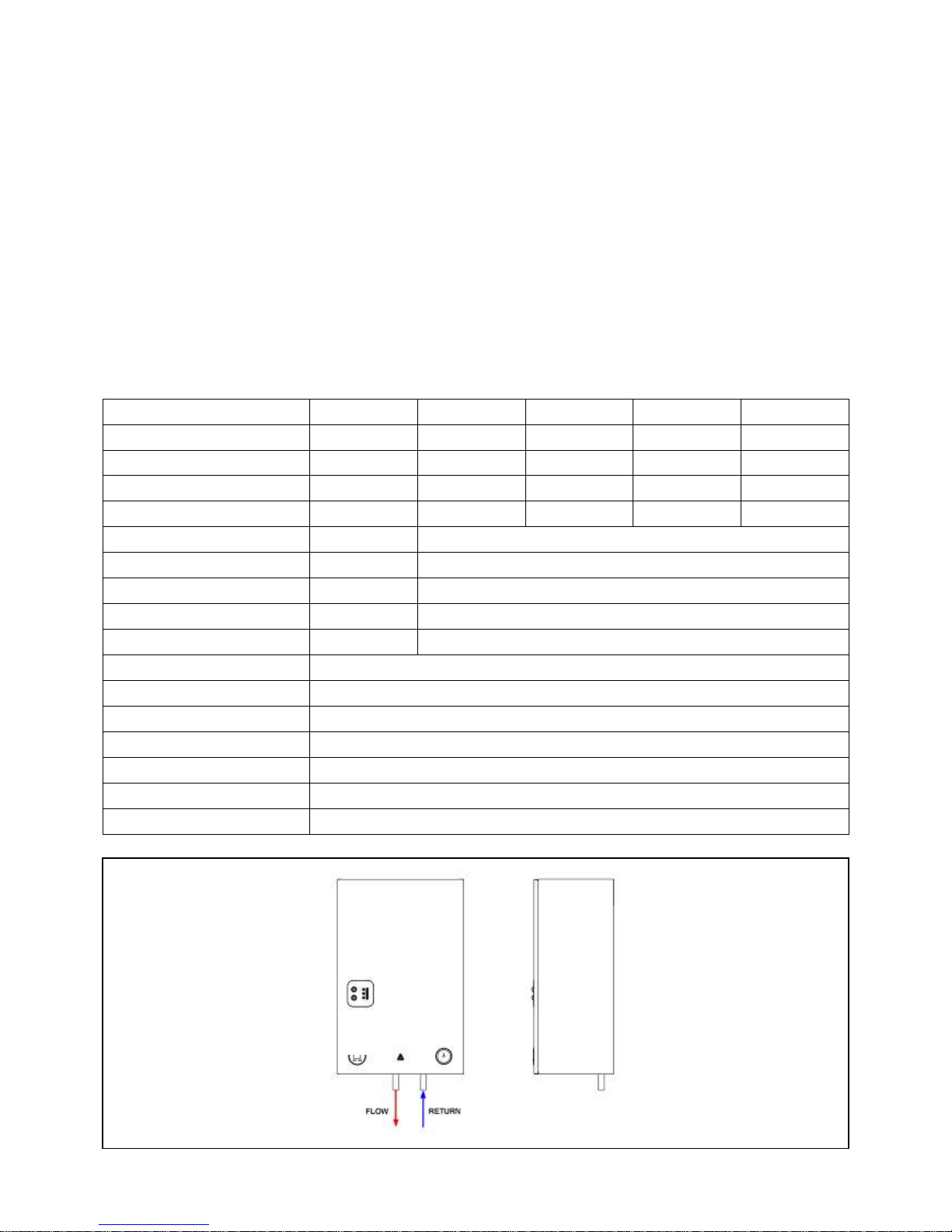
INSTALLATION
FLOW & RETURN
CONNECTIONS
Page 9
Regulations
Installation of the boiler must comply with the following
British Standards and Regulations:
BS5449 – Forced circulation hot water central heating
systems.
BS7074-Part 1: Code of practice for sealed water systems.
The Building Regulations: Part ‘L’ (Northern Ireland)
Current I.E.E. Regulations
Local water undertaking By-laws.
Health and Safety at Work Act
The installer should be aware of his responsibilities under
the Act and provide where necessary, appropriate
protection for persons carrying out the installation. In the
interests of safety a competent engineer should install the
boiler and all wiring must be carried out in accordance
with current IEE regulations.
IMPORTANT
ALL ELECTRICAL WORK MUST BE CARRIED OUT BY A
QUALIFIED ELECTRICAL ENGINEER TO CURRENT IEE
WIRING REGULATIONS.
SITING THE BOILER
IMPORTANT: NOT TO BE INSTALLED IN A SHOWER
COMPARTMENT OR BATHROOM
The boiler is designed to be fitted in an upright position
only. Ensure adequate clearance is allowed for making
water connections as the boiler can only be fully serviced
from the front. The boiler must also be fitted in a dry well
ventilated position, which is not subject to adverse
temperature conditions. (See ventilation requirements).
Care should be taken when siting the appliance to make
sure adequate access is available for future servicing of the
appliance. Please note that the PCB and heat exchanger
assembly may require removal during such times.
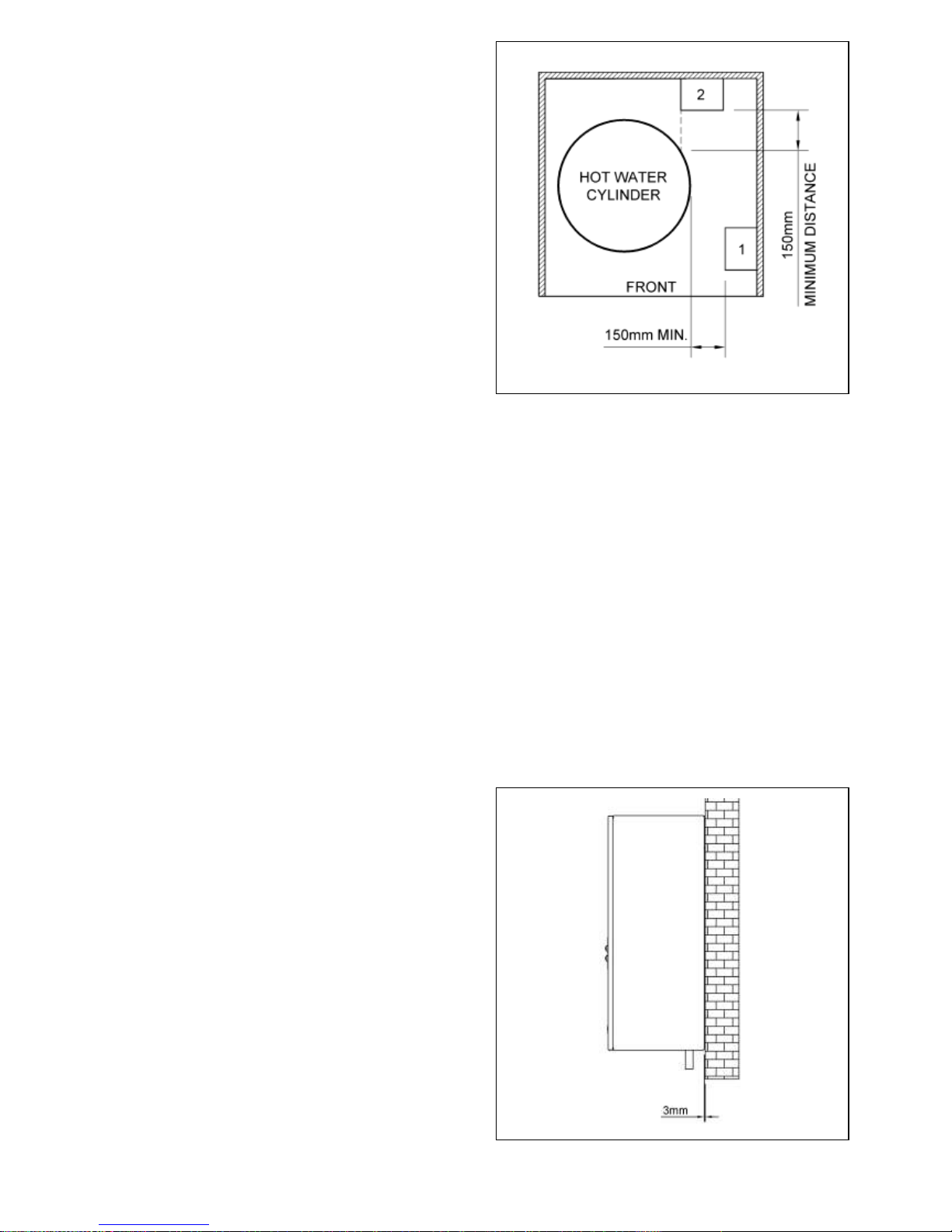
When installed in a compartment with a hot water cylinder
(see Fig. 1), we recommended that the boiler is fitted in
position 1, if fitted in position 2 provision should be made
at the front of the boiler to enable the removal of the front
casing. In both cases, where any additional equipment like
a hot water cylinder or system controls are to be fitted
after the boiler has been installed, attention should be
given to ensure that they do not restrict access to the
boiler for servicing.
UNPACKING THE BOILER
Carefully open the boiler carton, remove boiler and place
in a safe place until required.
NOTE: ALWAYS STORE THE BOILER IN A DRY PLACE PRIOR
TO FITTING.
FIXING BOILER TO THE WALL
The boiler should be fitted to a suitable wall in an upright
position.
Using fixing dimensions supplied work out position of
boiler, mark three holes and fix wall mounting bracket to
the wall with suitable fixings.
Hang boiler onto wall mounting bracket and secure
bottom of boiler to the wall, appliance to be fixed 3mm
from the mounting surface. (see Fig 2)
9
Fig.
Fig. 2
Page 10
VENTILATION REQUIREMENTS
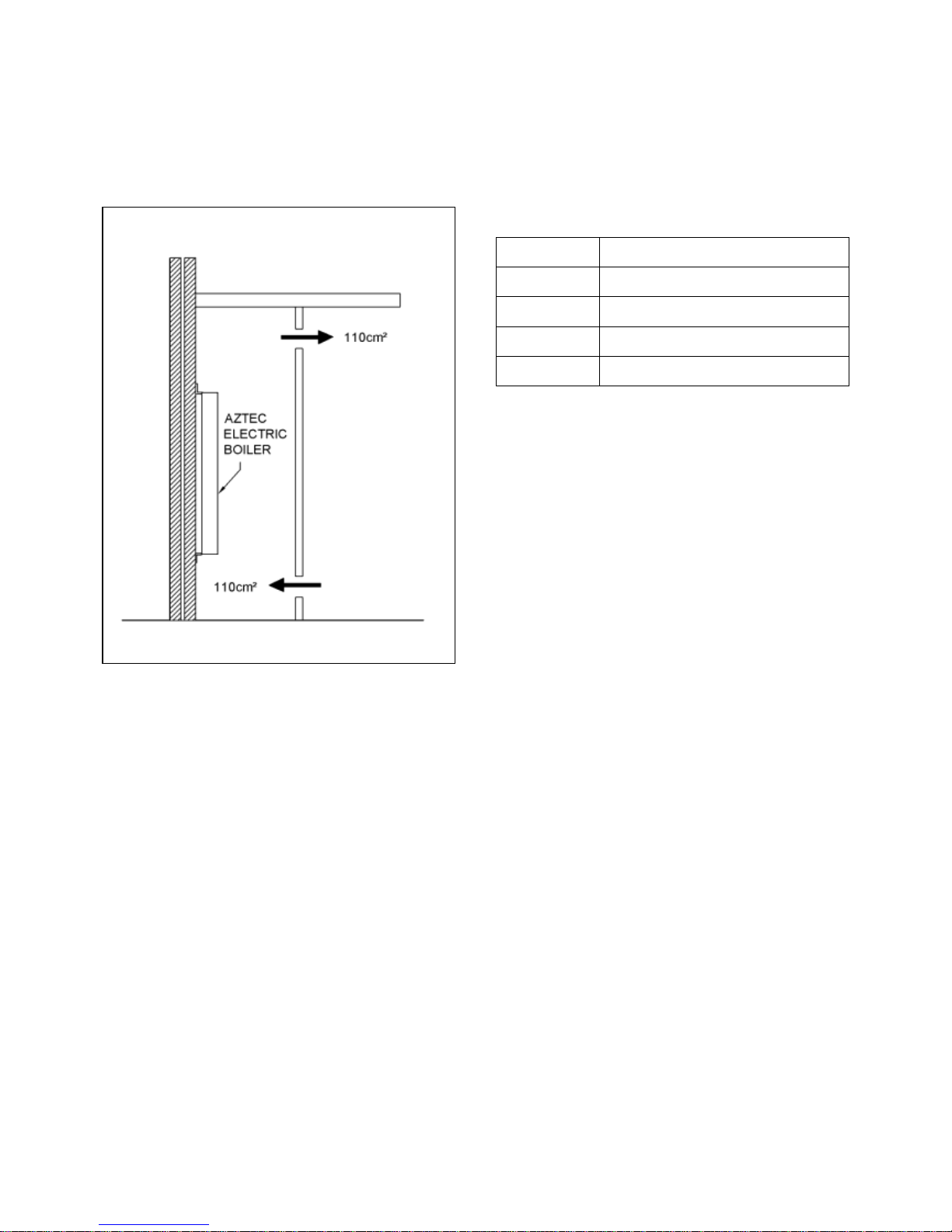
If the appliance is to be fitted in a confined space or
compartment with a potential ambient temperature of
60˚C or more, it is strongly recommended that adequate
ventilation is provided to prevent the overheating of the
boiler controls. Aeration of 110 cm² will be required to the
compartment, in both high and low positions (see Fig. 3).
WATER SYSTEM
IMPORTANT: USE ONLY COMPRESSION FITTINGS WHEN
CONNECTING THE BOILER TO THE CENTRAL HEATING
SYSTEM.
The installation must comply with the requirements of the
following codes of practice.
BS 5449 Part 1 Forced Circulation Hot Water Systems
BS 7074 Part 1 Code of Practice for Sealed Water
Systems.
BS 7593 Treatment of water in domestic hot water central
heating systems.
The water system must be thoroughly flushed out with
cold water without the pump in position.
Refit the pump and fill the system. Vent all air from
system. Clear any air locks and examine the system for
water leaks.
IMPORTANT: ENSURE ALL SERVICE VALVES ARE IN OPEN
POSITION.
10
Ensure boiler is fitted with flow pipe at top and return
pipe at bottom.
The boiler is supplied with Dia. 22mm tail pipes top and
bottom for connection to system.
The boiler must be installed using 22mm compression
fittings both top and bottom. The Aztec range of boilers
are low water content boilers so require a good flow rate
at all times (see chart).
Model
Minimum Flow Rate / Min
6kW
8 litres
9kW
10 litres
11kW
11 litres
12kW
12 litres
Aztec boilers are approved for use on fully pumped open
vented systems and sealed systems. When fitting on a
sealed system a 3 bar safety valve must be fitted to
system, where thermostatic radiator valves are fitted it will
be necessary to fit a bypass to obtain minimum flow rates.
IMPORTANT: IF MINIMUM FLOW RATES ARE NOT
OBTAINED THE BOILER MAY GO TO LOCK OUT ON HIGH
LIMIT THERMOSTAT.
Where more than 1 boiler is fitted refer to multiple boiler
instructions. System must be flushed out before adding
inhibitor to BS 7593: 1992 treatment of water in central
heating boiler.
IMPORTANT: THIS BOILER IS TO BE FITTED ON FULLY
PUMPED SYSTEMS ONLY.
Fig. 3
Page 11
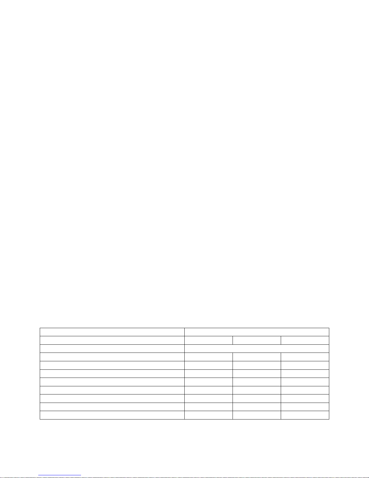
SEALED WATER SYSTEM REQUIREMENTS
The installation must comply with the appropriate
requirements of the current issue of BS4814, BS5449,
BS6798 and BS7074 Part 1 and 2.
Safety Valve
A 3 bar safety valve is fitted within the unit. The drain must
be routed to the outside of the building. The drain must
not discharge above an entrance or a window or any public
access area, be clear of any electrical fittings and
positioned so that any discharge can be seen.
Expansion Vessel Capacity
A diaphragm type expansion vessel, conforming to the
current issue of BS4814. The expansion vessel must be
connected to the systems at a point close to the inlet side
of the circulating pump. The expansion vessel volume
depends on the total water system volume and the initial
system design pressure. For any system an accurate
calculation of vessel size is given in the current issue of
BS5449 and BS7074 Part 1.
The water content of the boiler is given in the technical
specification. Note a higher initial design pressure requires
a larger volume expansion vessel.
The charge pressure must not be less than the static head
of the system, which is the highest point of the system
above the expansion vessel.
Capacity of Expansion Vessel
Where design information is not complete the following
chart (page 11) can be used for selecting the size of the
vessel, it should be noted that the size given in the table
take account of fault conditions.
NOTE: Failure to ensure the correct vessel size could
result in premature failure of the expansion vessel which
in turn may adversely affect other components in the
system i.e. circulating pump and diverter valve.
System Temperature
The normal running temperature of the system is 75°C, if a
fault was to occur then the safety device would allow the
system temperature to rise to 100°C. It is recommended
that this figure be used in the calculations of vessel size.
Expansion Vessel Connection
The expansion vessel should be connected in the neutral
part of the system this being the return pipe work close to
the boiler, refer to sealed system pipe work layout
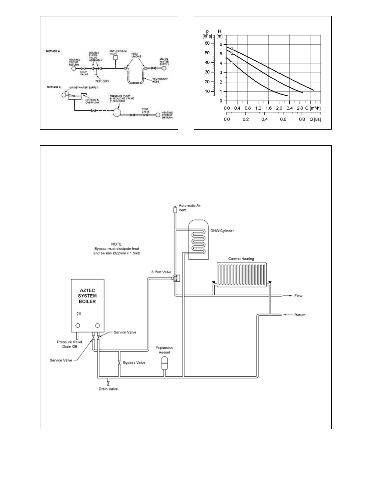
drawing.(Fig. 8)
Pressure Gauge
A 0 to 4 bar pressure gauge is fitted within the unit.
Inhibitor
If using an existing system take care to drain down the
entire system including the radiators then thoroughly
clean out before fitting the boiler. Attention is drawn to
the current issue of BS5449 and BS7593 on the use of
inhibitors in central heating systems.
Drain Tapping
A drain tapping is provided on the boiler. An additional
tapping must be provided at the lowest point of the
system, which will allow the entire system to be drained.
System Makeup
Water loss from the system should be replaced from a
makeup vessel connected to the system. This vessel should
be higher than the top of the system. Alternatively
provision can be made by pre-pressurisation of the system
via a temporary hose connection and through a double
check valve (non-return) and stop valve.
There must be no permanent connection to the mains
water valve supply even through a non return valve.
Safety valve setting (bar gauge)
3 Bar
Vessel charge and initial system pressure (bar gauge)
0.5
1.0
1.5
Total water content of system (litre)
Vessel volume (litre)
25
2.3
3.3
5.9
50
4.7
6.7
11.8
75
7.0
10.0
17.7
100
9.4
13.4
23.7
125
11.7
16.7
29.6
150
14.1
20.1
35.5
175
16.4
23.4
41.4
200
18.8
26.8
47.4
11
Page 12
12
PUMP FLOW CURVE
Fig 9
ALTERNATIVE METHODS OF
FILLING A SEALED SYSTEM
Fig 8
SEALED SYSTEM
Fig 10
Page 13
WIRING INSTRUCTIONS
All electrical work must be carried out in accordance with
current IEE wiring regulations (seventeenth edition).
Before commencing installation check power supply to
property to ensure that there is sufficient current and
voltage available for size of boiler fitted. Take into
account requirements of other electrical appliances, the
boiler must be connected to the mains supply by means
of a double pole linked switch with 3mm contact gap in
both poles.
IMPORTANT:
After completing electrical installation work preliminary
safety checks should be carried out as described in
BS 7671:2001
The electrical supply requirements:
The 6kW boiler supply should meet the requirements of
EN61000-3.3.
The 9kW and 11kW boiler must be installed in premises
having a service supply > 100A per phase and meet the
requirements of IEC 60417-5855.
The 12kW boiler must be installed in premises having a
system impedance of not more than 0.1939 + 0.1939Ω.
A double pole RCD with a trip level sensitivity of 30ma can
be used capable of breaking full load current to
BS EN61008: 1994
NOTE: RCD unit can be used as the isolating switch if
mounted close enough to the boiler.
Miniature circuit breakers MCB’s MUST be fitted between
RCD unit and boiler and RCD and any external controls.
Refer to technical specification. For MCB ratings refer to
wiring diagram.
It is important the correct size MCB is used in the supply
from the RCD to the boiler. An additional MCB rated 6A
will be required to supply the external controls.
ELECTRICAL CONNECTIONS
WARNING: THIS APPLIANCE MUST BE EARTHED.
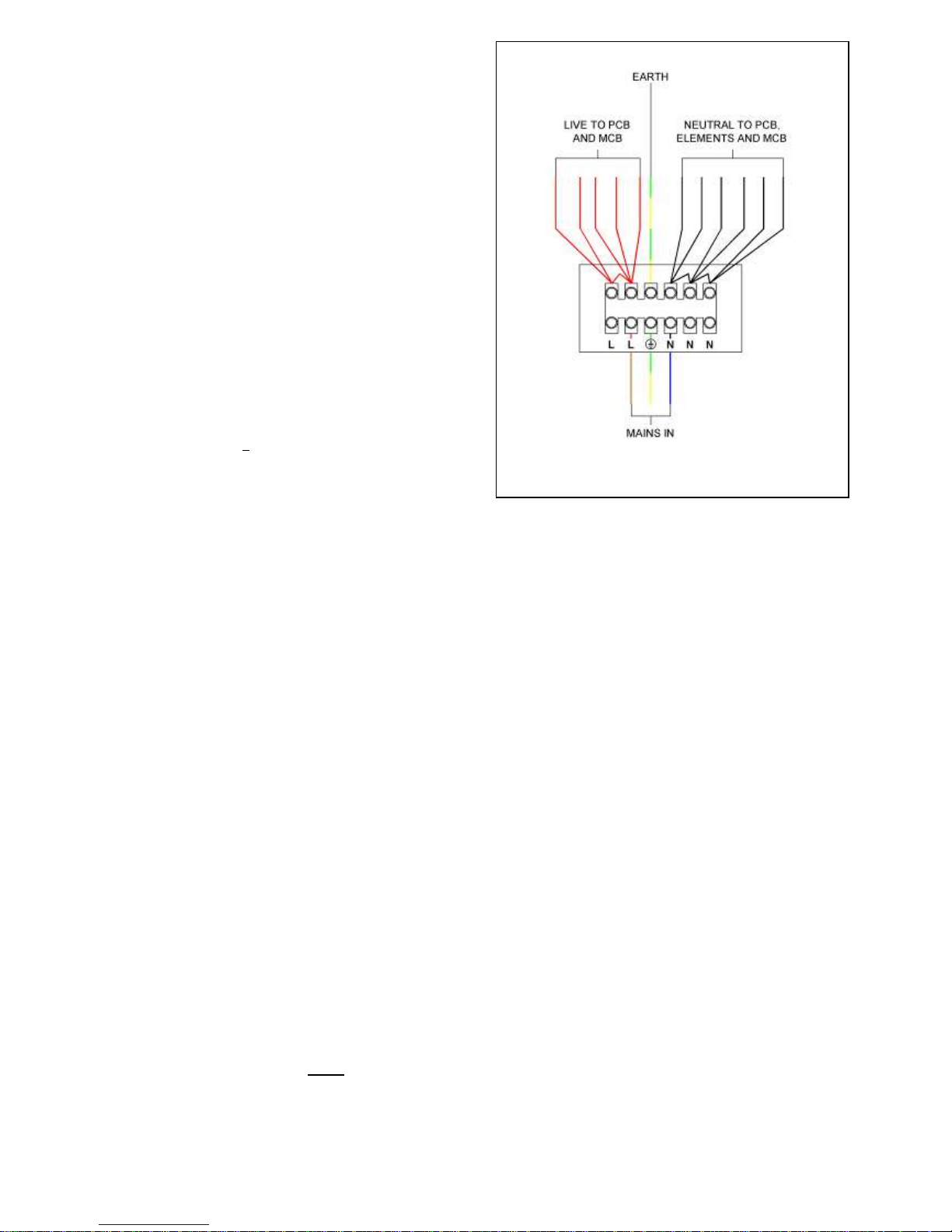
The mains connection block is located inside the boiler on
a bracket at the bottom left hand side of the boiler which
can be directly wired to the boiler MCB. Use the correctly
rated cable.
Where the pump is wired directly back to the boiler both
live and neutral connection must be used with the earth
being wired back to the earth post. This is important as the
pump is controlled by a switched neutral. This also applies
to pumps being controlled by a relay.
IMPORTANT: CORRECT POLARITY MUST BE OBSERVED
WHEN BRINGING THE MAINS SUPPLY INTO THE BOILER.
13
TERMINAL CONFIGURATION
Page 14
14
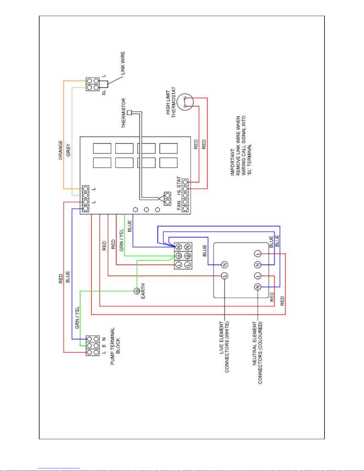
INTERNAL WIRING
(SHOWING 3 ELEMENTS 6 & 9 kW model
Page 15
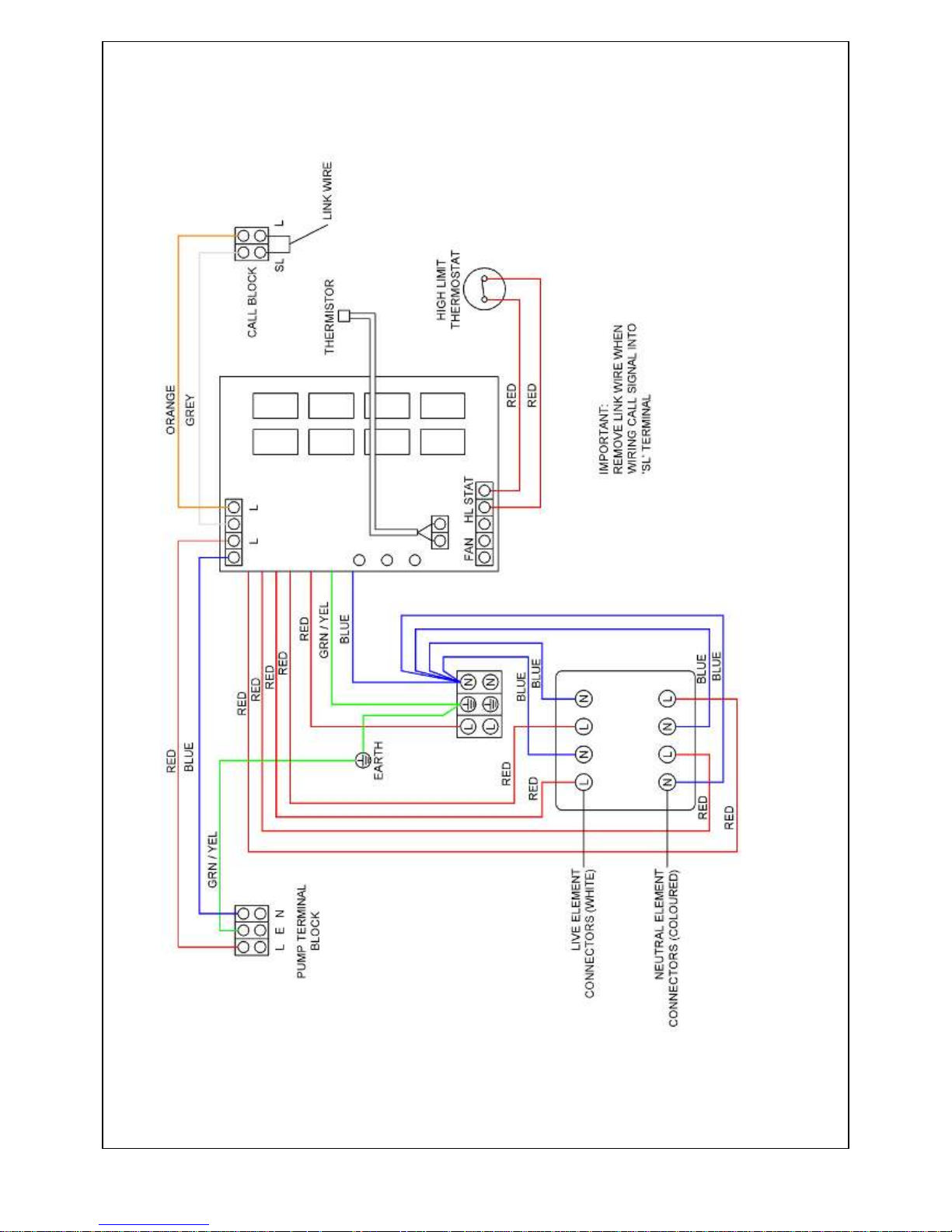
15
INTERNAL WIRING
SHOWING 4 ELEMENTS 11 & 12 kW model
Page 16
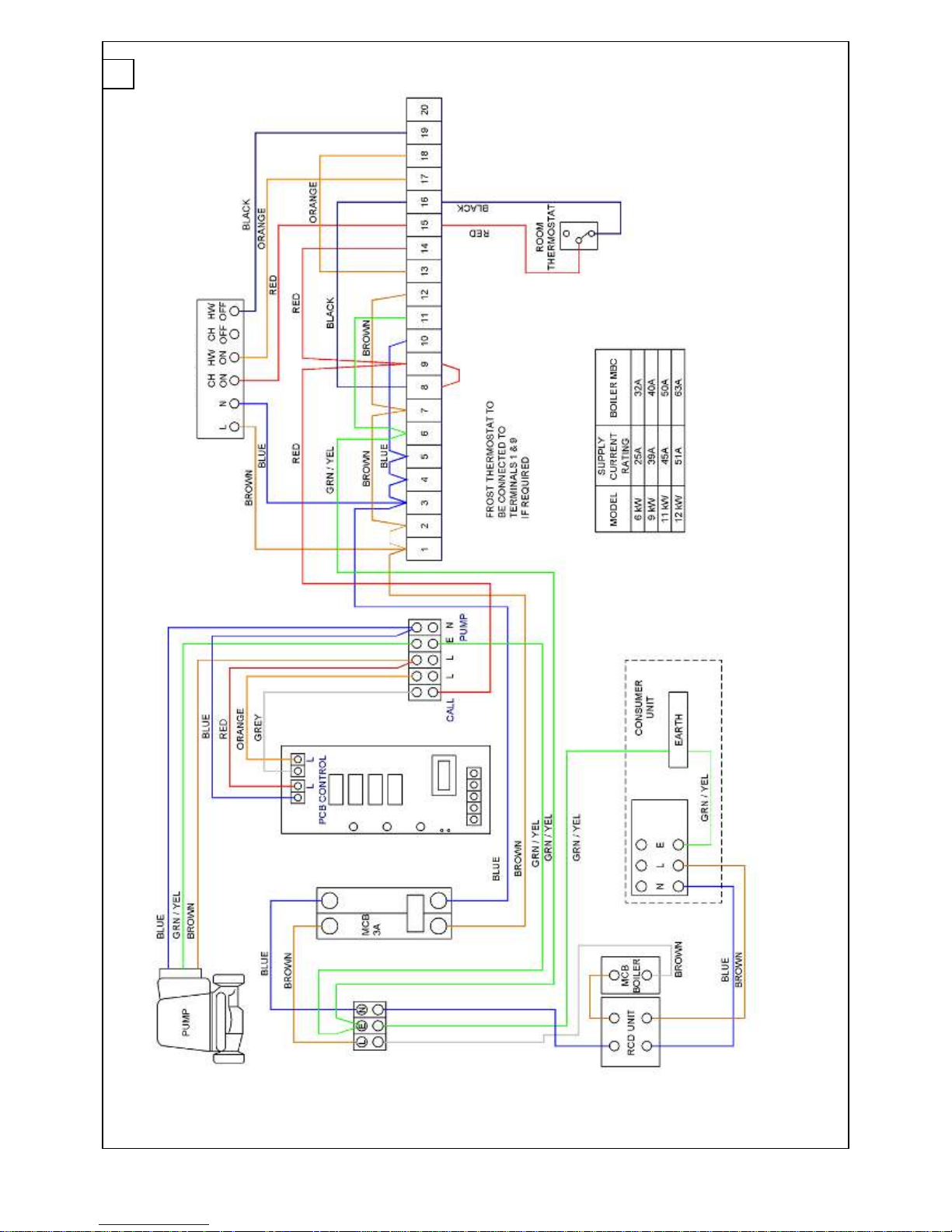
16
WIRING DIAGRAM FOR HEATING ONLY SYSTEM CONTROL
EXTERNAL PROGRAMMER
WIRING
Page 17
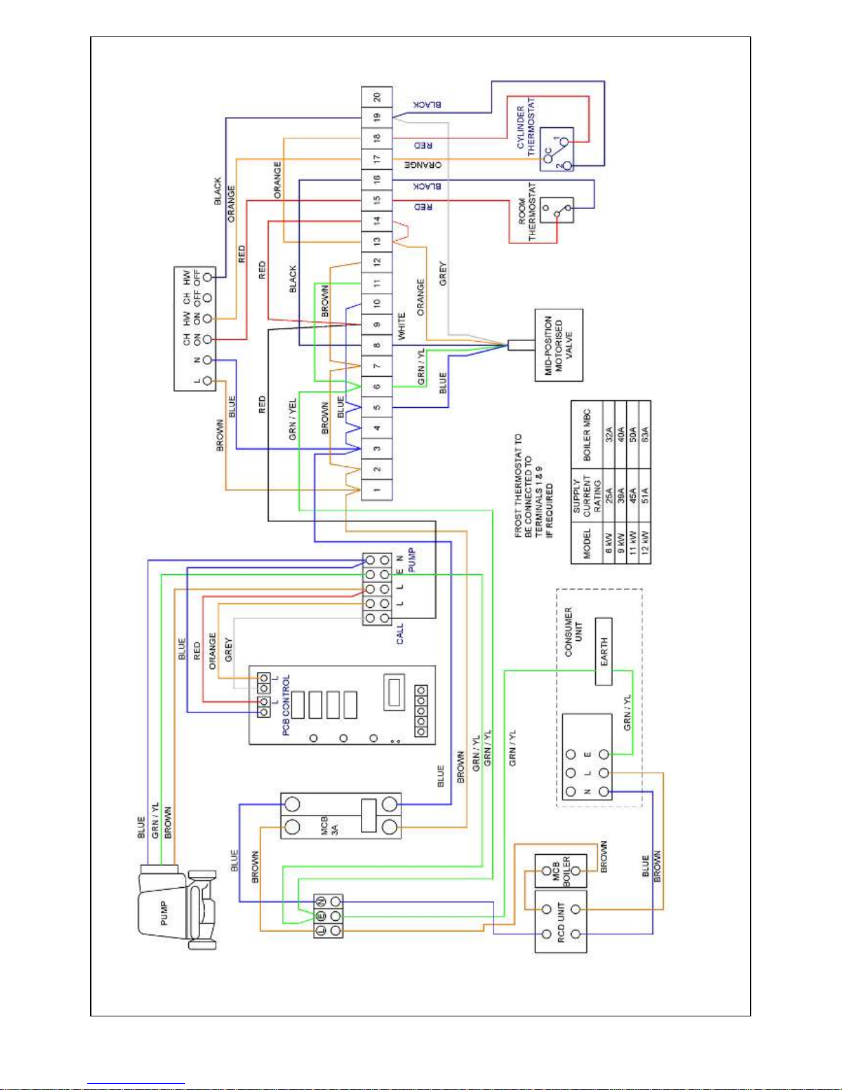
17
WIRING DIAGRAM FOR ‘Y’ PLAN SYSTEM CONTROL
EXTERNAL PROGRAMMER
WIRING
Page 18
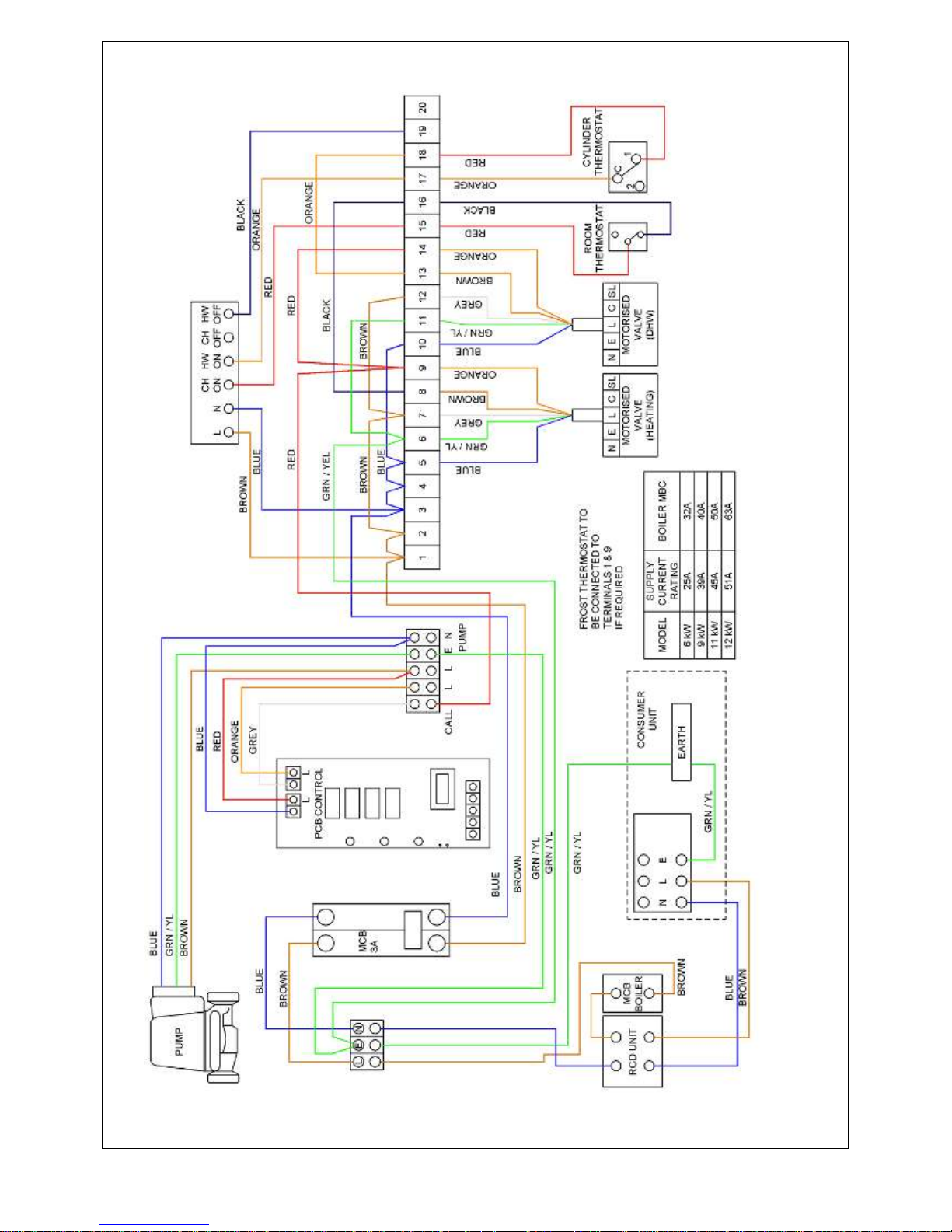
18
WIRING DIAGRAM FOR ‘S’ PLAN SYSTEM CONTROL
EXTERNAL PROGRAMMER
WIRING
Page 19

SERVICING
To ensure reliable operation of your Aztec electric system
boiler, it is recommended that you have your boiler
serviced once a year.
The person(s) who services or carries out any remedial
work, i.e. electrical fault finding must have suitable
engineering qualifications.
Isolate mains supply before out any service work.
Check all electrical connections on PCB and electric
elements to ensure they are secure and clean.
Check electrical insulation on wiring.
Ensure all air grilles are clean and free from obstructions.
Inspect seals around elements and also, the heat
exchanger’s top and bottom flanges.
PARTS REPLACEMENT
Casing Removal
Isolate electrical supply to the boiler.
Remove 4 fixing screws securing front case in position.
Disconnect temperature button cables from the pcb.
This will allow the front casing to be removed.
IMPORTANT: All electrical connections should be
checked. Loose connections can cause problems.
The boiler is fitted with a manual reset high limit
thermostat. Before replacing any part, ensure that
thermostat does not require resetting.
PCB ASSEMBLY REPLACEMENT
Note: The PCB is supplied with the element jumper fitted
suitable for 11kW and 12kW boilers. When fitted to a 6kW
or 9kW boiler, the element jumper must be removed.
Ensure electrical supply to the boiler is isolated.
Remove the 4 fixing screws and washers (2 at top and 2 at
bottom) securing the front casing. Disconnect the
temperature button cables from the pcb and remove the
front casing.
Disconnect the pump and call plug, the thermistor
plug, the fan (where fitted) and high limit thermostat plug.
Disconnect all element cables apart from the rear
element. N.B. Take note of wiring arrangement before
disconnecting.
Now remove the grey pipe insulation, it is now possible to
disconnect the remaining element.
With all elements disconnected, again taking note of
wiring arrangement, carefully disconnect and remove the
element cables from the PCB. Important: Care must be
taken.
Disconnect the remaining red and black power cables from
the PCB.
For ease of access disconnect from the main terminal
block both the red and black cables and also the power
input cables, leaving the earth cable connected.
Free both the pump and call terminal blocks by removing
the terminal block fixing screws.
Finally remove the 4 fixing screws holding the pcb
mounting bracket in position and remove the PCB from the
unit.
Re-fit in reverse order on reassembly always refer to
wiring diagram.
HIGH LIMIT THERMOSTAT REPLACEMENT
Ensure electrical supply is isolated to boiler
The high limit thermostat can be found fixed to top side
face of boiler.
Remove 2 terminal connectors from high limit thermostat.
Remove 4 clamping nuts and clamp plate and remove high
limit thermostat.
Important when replacing thermostat ensures a heat sink
compound is used between back of thermostat and face of
boiler. (See diagram for positioning).
Inspect retaining straps and replace where necessary.
19
Page 20
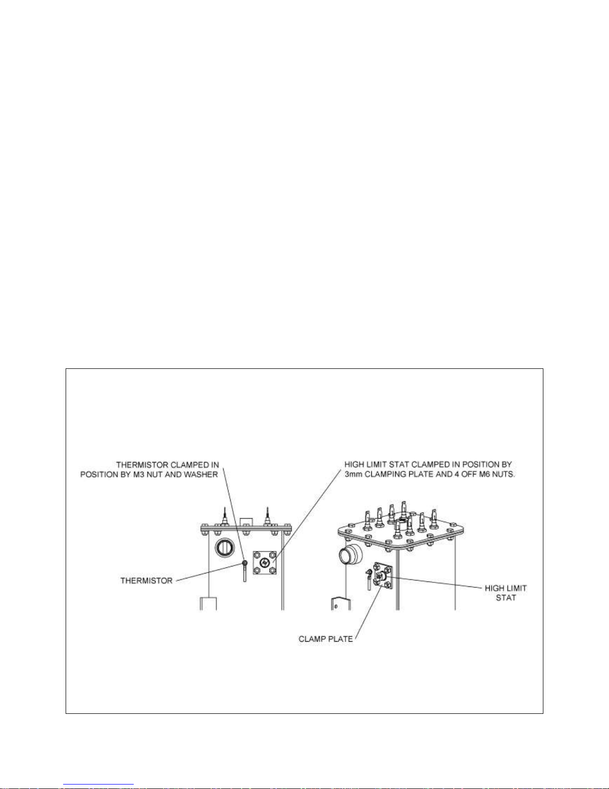
THERMISTOR REPLACEMENT
Isolate electrical supply to boiler.
The thermistor is located fixed to top side of the boiler at
the side of the high limit thermostat.
Disconnect from PCB board and remove nut and retaining
washer.
Important when replacing thermistor ensure a heat-sink
compound is used between thermistor and boiler body
(see diagram for positioning).
When replacing front casing, ensure the temperature
control switches are re-connected to the pcb.
ELEMENT REPLACEMENT
Isolate electrical supply to boiler.
Drain down system.
Disconnect terminal connectors from high limit
thermostat
Remove thermistor from body.
20
Disconnect electrical elements and earth wire.
Disconnect compression fitting top boiler and pump
connection on base of boiler.
Remove screws from securing bracket on back of the boiler
onto back casing.
Boiler unit can now be carefully removed.
Remove 12 fixing screws on top flange with and withdraw
the element assembly.
Remove damaged element.
Refit in reverse order and ensure element seals are fitted.
Check for continuity through 2 terminals on each element.
IMPORTANT: Inspect all seals and change where
necessary.
Fig. 23
Fig. 11
Page 21
FAULT FINDING
Red LED permanently illuminated indicates one of the
following faults.
High limit thermostat has operated or faulty electrical
connections
The high limit thermostat is fitted to the front top of the
copper heat exchanger and secured in position with 2
retaining clamps. Check electrical connections on
thermostat and PCB to check thermostat has not failed
using a multi meter check continuity across terminals of
thermostat. To reset press red button in centre of
thermostat. Thermostat may have tripped due to one of
the following:
Faulty circulation pump.
Isolation valve on system closed.
Air trapped in system.
Out of calibration limit thermostat.
Temperature settings on PCB board incorrect.
No water in system.
Thermistor
The thermistor is fitted to the front top of the heat
exchanger and secured in position with a clamp, the other
end terminates with a white connector that plugs on to the
PCB Check the connections on the board to make sure it is
correctly fitted; also inspect the thermistor for any broken
wires.
Mains Inlet Wiring
If the mains supply to the boiler is wired incorrectly on the
inlet terminal block. Check polarity.
PCB Damage
Inspect the LED lights and the boiler temperature control
adjuster for any damage to connections to PCB controller.
Voltage Drop
If the voltage drops below 207 volts.
Red LED flashes indicates one of the following faults.
Poor electrical connection
Check the electrical connections to the elements and the
PCB controller, a poor controller would show up a fault.
Element Failure
To check elements for failure, disconnect each individual
element and check continuity through the element if there
is continuity between the two terminals the element is ok.
Check each element individually replacing the electrical
connectors after testing.
Element Cables
If there is a break in the element cable, this would show up
as a fault. Check all element cables and connections.
PCB Running Temperature
The PCB control unit has a built in temperature control
sensor which protects the PCB from overheating, if the
board was to overheat the sensor would detect the high
temperature and shut off the power to the board until the
board temperature has returned to normal running
temperature. The boiler will resume operation but the red
light will continue to flash to indicate a fault has occurred.
To reset the board the power must be turned off for 30
seconds then switched on again.
On the 9, 11 and 12 kW boilers a cooling fan is fitted to the
heat sink if this has failed, it would cause the PCB to
overheat. To differentiate between a temperature or
element problem, switch off the power supply to the boiler
allow the boiler to cool down then switch the power back
on, if the LED continues to flash then check elements and
connections.
Green LED
If the green LED is illuminated but the boiler is not
functioning, check that any external controls fitted are
calling for heat. If no external controls are fitted check that
link wire is in place on call terminal block (refer to wiring
diagram Fig 1).
Blown Fuse on board
If there is power to the boiler but no LED illuminated then
the fuse on the PCB may have blown. The fuse is located
above the PCB transformer (fuse type 20mm 630Ma anti
surge Bessman type S560)
The fuse may have blown due to one of the following:
When multiple boilers are fitted and a larger pump is used.
If the pump is wired directly into the PCB the fuse may
need upgrading. (see page 11)
If the call terminal is used to supply power to ancillary
controls.
Element Jumper Connections
Fitted on all models.
AZTEC
JUMPER 1
JUMPER 2
11 & 12kW
Back
Back
6 & 9kW
Front
Back
21
Page 22

RCD UNIT TRIPS
Check that the RCD unit is correctly rated for boiler size. If
under size change. Inspect mains terminal block wiring for
short-circuiting. Check electrical elements for earth
continuity, if element is found to be faulty fit new element.
Thermistor Values
Temperature (°C)
Resistance Value (Ohms)
0
32554
5
25339
10
19872.2
15
15698.5
20
12487.7
25
10000
30
8059.1
35
6543.7
40
5329.9
45
4371.7
50
3605.3
55
2988.7
60
2490
65
2084.4
70
1753
75
1480.9
22
Page 23
23
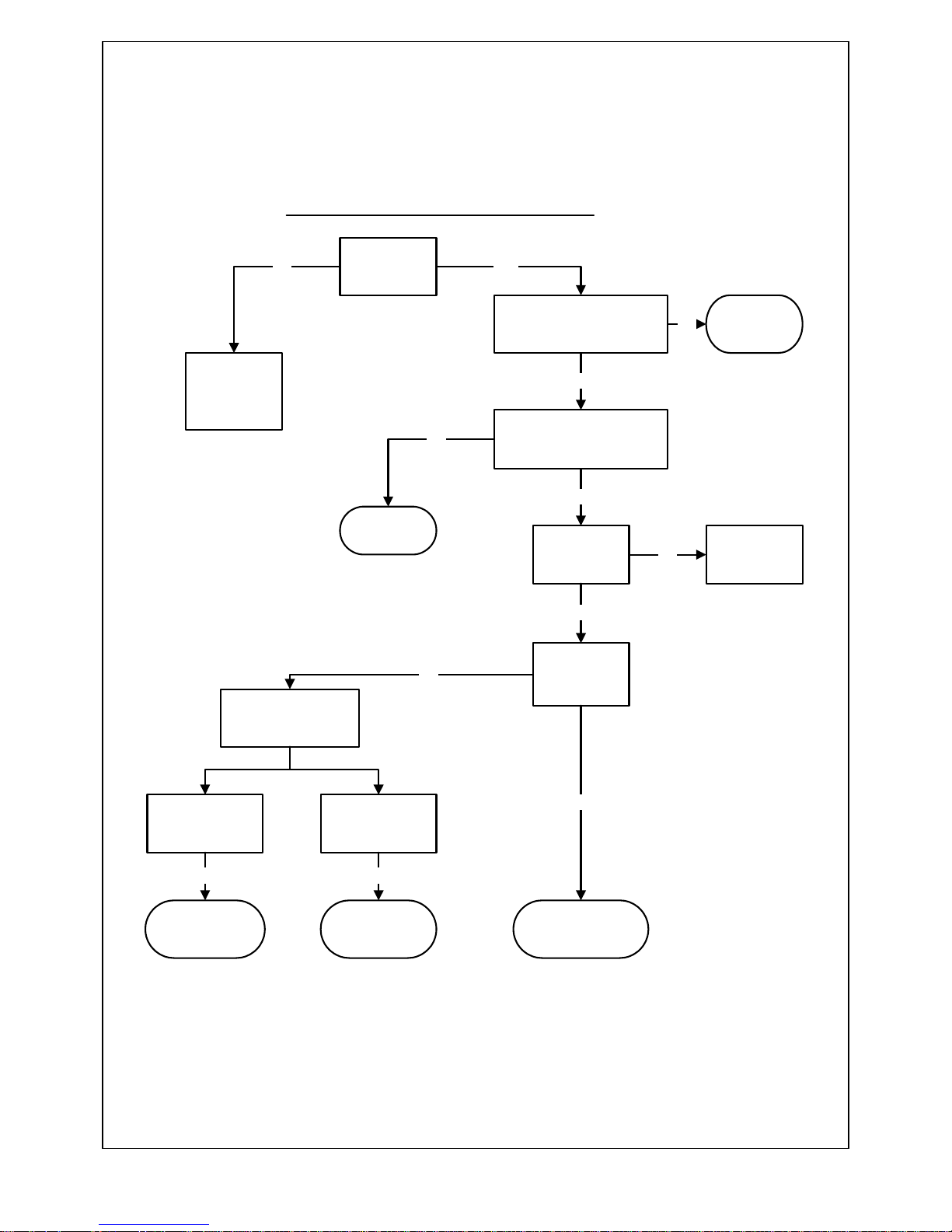
NO HEAT - PERMANENT GREEN LIGHT
IS THE
PROGRAMMER
TURNED ON I.E.
CALL SIGNAL?
IS THE HEAT EXCHANGER
GETTING UP TO
TEMPERATURE - AMBER ON
OR FLASHING?
CHECK
EXTERNAL
CONTROLS ARE
CALLING FOR
HEAT
ARE ISOLATING
VALVES OPEN?
IS THE PUMP
RUNNING?
OPEN
ISOLATING
VALVES
CHECK LIVE & NEUTRAL
TO PUMP
IS NEUTRAL
CONNECTION LIVE?
LIVE & NEUTRAL
OK?
IMPORTANT!
THE PCB ON THIS BOILER SWITCHES NEUTRAL NOT LIVE
CHECK SYSTEM
PRESSURE & PIPE-
WORK FOR AIRLOCKS
CHANGE PCBCHANGE PUMP
NO
YES
NO
YES
NO
YES
YESYES
CHANGE PCB
NO
IS CALL WIRE LIVE I.E. LINE
VOLTAGE?
CHECK
ELECTRIC
SYSTEM
CIRCUIT
NO
YES
YES
Page 24
24
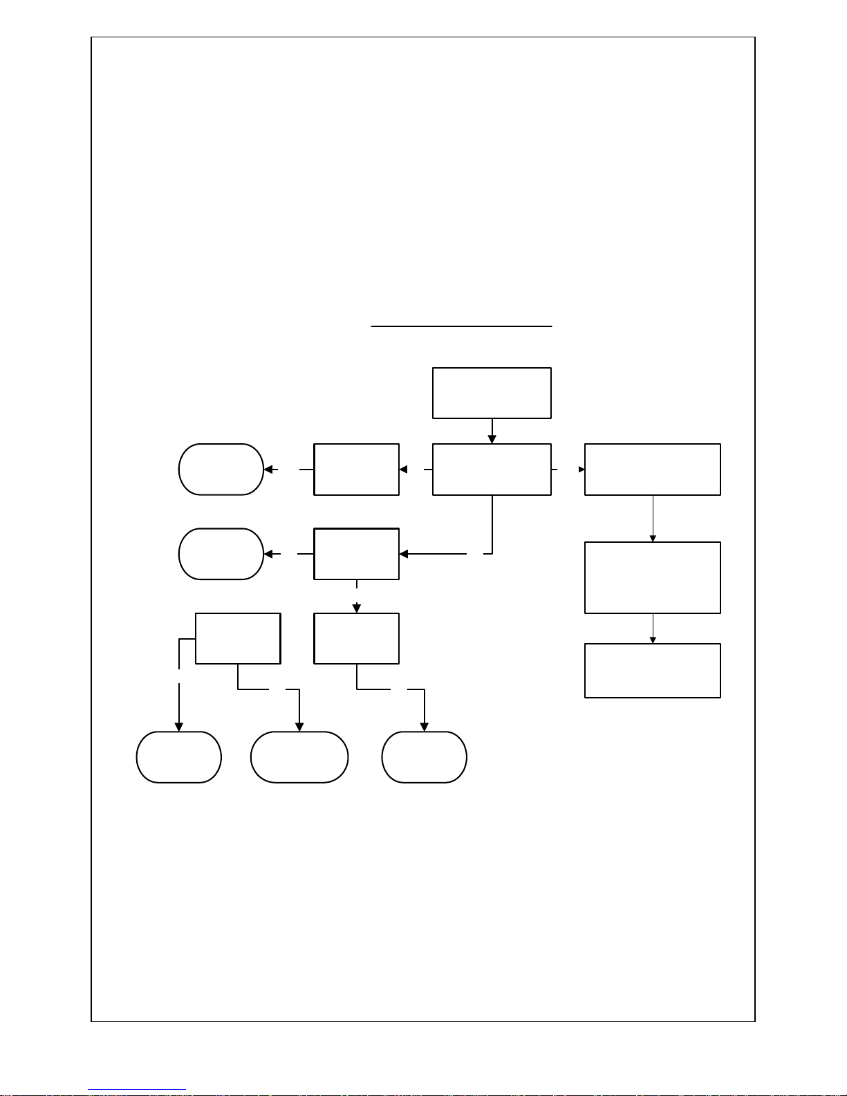
FLASHING RED LIGHT
TURN BOILER OFF FOR
30 SECONDS TO RESET
PCB
HAS THE RED LIGHT
STOPPED FLASHING?
OVERHEATED PCB
AMBIENT TEMP TOO HIGH
IS THE BOILER 6
OR 9KW?
NO YES
ARE CABLES
AND
CONNECTIONS
OK
NONO
IS THERE
POWER TO ALL
ELEMENTS
YES
CHANGE PCB
NO
CHECK THERE IS
SUFFICIENT VENTILATION
AROUND BOILER
REF.PAGE 6 OF
INSTRUCTION MANUAL
CHECK THAT THE FAN IS
NOT DEFECTIVE,9,11,12Kw
ONLY
IS THERE
CONTINUITY
ACROSS THE
ELEMENTS
MAKE SURE
JUMPER HAS
BEEN REMOVED
REPLACE
CABLES
REPLACE
ELEMENT OR HEAT
EXCHANGER
NO
CHANGE PCB
YES
YES
Page 25
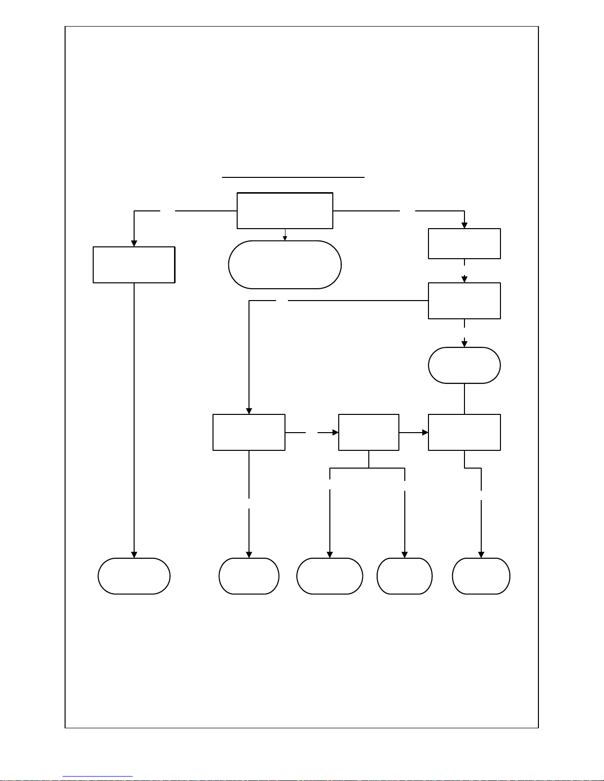
25
PERMANENT RED LIGHT
IS INCOMING POWER
SUPPLY OK?
REPLACE
THERMISTER
CABLE
HAS THE HIGH LIMIT
STAT TRIPPED?
REPLACE FAULTY
CABLES OR
CONNECTIONS
DOES THE BOILER GO
FROM GREEN TO
AMBER THEN RED?
CHANGE PCB
REFIL TO 1 BAR
&CHECK FOR
LEAKS
IS THE SYTEM
PRESSURE
SUFFICIENTLY
CHARGED?
IS THE THERMISTER
CABLE FAULTY?
YES
ARE THE LIMIT
STAT
CONNECTIONS
OK?
NO
NO
NO
CHANGE PCB
YES
NO
CHECK INCOMING SUPPLY
CROSS POLARITY?
CORRECT VOLTAGE?
CORRECT RCD?
YES
DOES THE BOILER
GO STRAIGHT TO
RED LIGHT?
YES
YES
RE-SET HIGH LIMIT
STAT
YES
Page 26
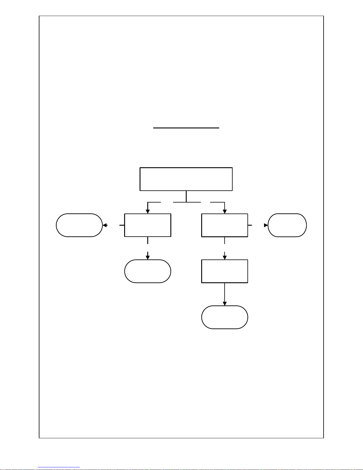
26
NO GREEN LIGHT
IS THERE POWER TO THE
BOARD?
HAS THE FUSE
BLOWN ON THE
PCB?
HAS THE RCD
TRIPPED?
IS THERE
POWER TO LIVE
AND NEUTRAL?
YES NO
CHANGE FUSE
AND CHECK
PUMP
YES
NO
CHANGE PCB
CHECK SYSTEM
WIRING
RESET RCDYES
NO
Page 27
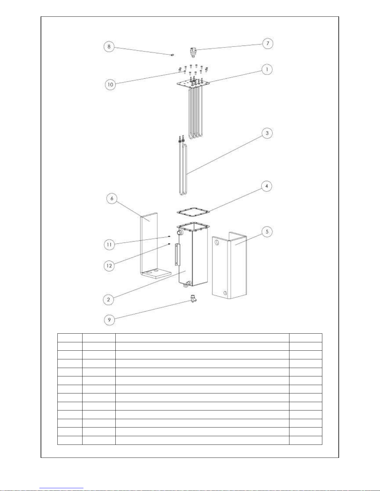
ITEM
PART No.
DESCRIPTION
QUANTITY
1
211501
ELEMENT FLANGE W.U.
1
2
211503
HEATER BODY W.U.
1 3 211701
3KW ELEMENT
4 4 211509
GASKET 1 5
211554
INSULATION FRONT & SIDES
1 6 211555
INSULATION REAR & BASE
1 7 207296
AUTOMATIC AIR VENT
1 8 211549
AIR VENT FITTING
1 9 99592
DRAIN COCK
1
10
91088
M6 x 16 HEX HD SETSCREW
12
11
92199
M6 SHAKEPROOF WASHER
12
12
94217
M6 HEX NUT
12
27
Page 28
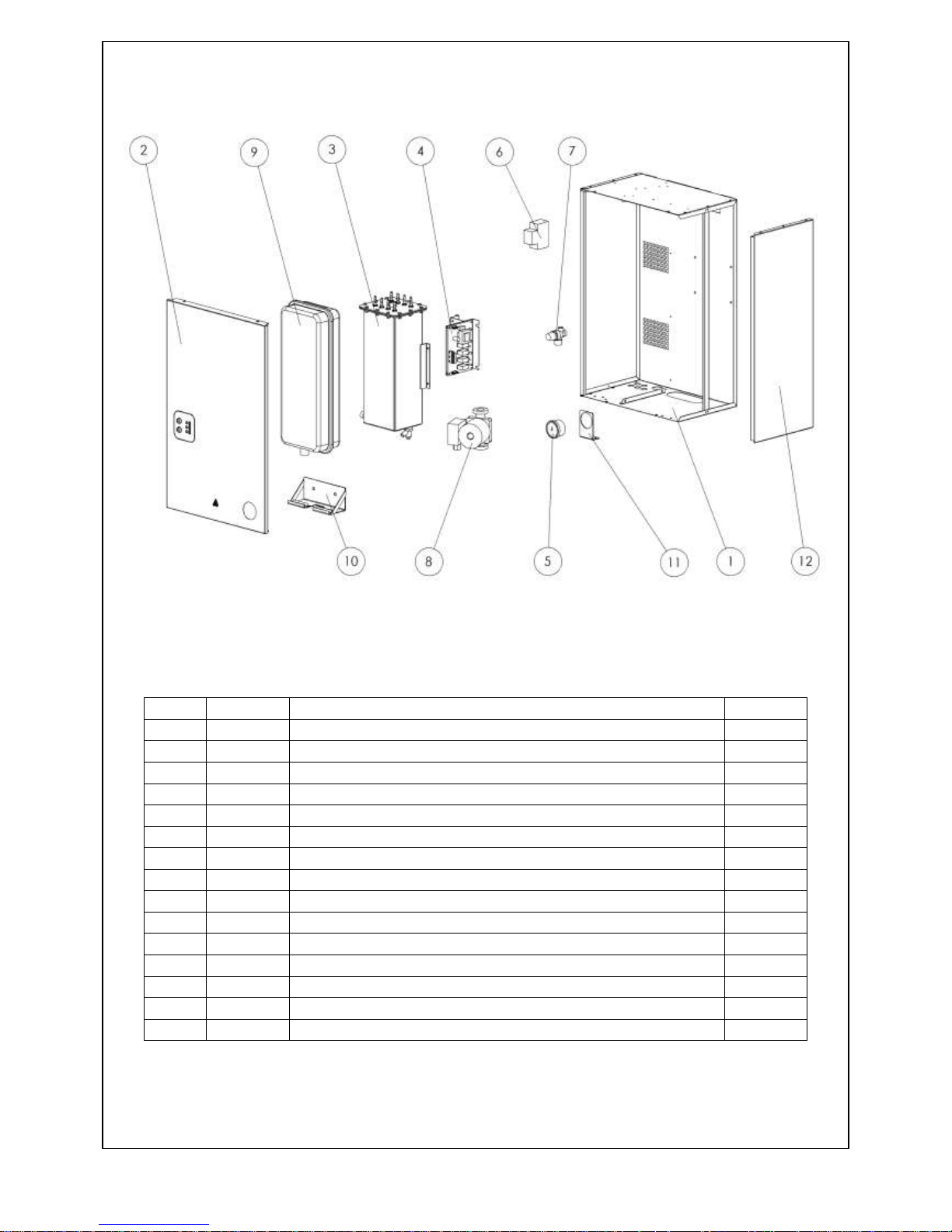
ITEM
PART No.
DESCRIPTION
QUANTITY
1
211510
BACK CASING ASSY
1 2 211515
FRONT CASING ASSY
1 3 211500
12KW HEATER ASSY
1 3 211560
11KW HEATER ASSY
1
3
211570
9KW HEATER ASSY
1
3
211580
6KW HEATER ASSY
1 4 211590
PRINTED CIRCUIT BOARD
1 5 211548
PRESSURE GAUGE
1 6 211532
MCB
2
7
221920
PRESSURE RELIEF VALVE
1 8 500014
PUMP
1
9
211529
6Ltr EXPANSION VESSEL
1
10
211540
EXPANSION VESSEL BRACKET
1
11
211547
PRESSURE GAUGE BRACKET
1
12
211519
SIDE PANEL
2
28
Page 29

29
Page 30

TR ENGINEERING LTD
UNIT 7, NEWTON CHAMBERS WAY
THORNCLIFFE INDUSTRIAL ESTATE
CHAPELTOWN
SHEFFIELD
S35 2PH
Tel: (0114) 2572300
Fax: (0114) 2571419
www.trianco.co.uk
© TR Engineering Limited
Copyright in this brochure and the drawings and illustrations contained in it is vested in TR Engineering Limited and neither the brochure or any
part thereof may be reproduced without prior written consent.
TR Engineering Limited's policy is one of continuous research and development. This may necessitate alterations to this specification.
August 2012
Item No. 211525 Issue 3
 Loading...