

Triadis Engineering Glide Computer and, Altair, Altair Pro Navigation System Owner's Manual

Glide Computer and Navigation System
Owner’s Manual
triadis engineering GmbH
Eichholzstrasse 7
CH-3254 Messen
Switzerland
Phone +41 (0) 31 768 15 15
Fax +41 (0) 31 768 15 16
http://www.triadis.ch
info@triadis.ch

Contents
1 Introduction 6
1.1 Pilot familiarisation . . . . . . . . . . . . . . . . . 6
1.2 Standard and Pro versions . . . . . . . . . . . . . 6
1.3 Parts list . . . . . . . . . . . . . . . . . . . . . . . 7
1.4 System description . . . . . . . . . . . . . . . . . 9
1.5 Instrument panel interface . . . . . . . . . . . . . 11
2 System functions 13
2.1 Power switch . . . . . . . . . . . . . . . . . . . . 13
2.2 External switches . . . . . . . . . . . . . . . . . . 13
2.3 Brightness adjustment . . . . . . . . . . . . . . . . 15
2.4 Data link . . . . . . . . . . . . . . . . . . . . . . . 15
2.5 Logger and GPS module . . . . . . . . . . . . . . 16
2.6 Radio/Comms/auxiliary device integration . . . . . 17
2.7 Audio output . . . . . . . . . . . . . . . . . . . . 17
2.8 Battery and power management . . . . . . . . . . 17
2.9 1-Wire peripherals . . . . . . . . . . . . . . . . . 18
3 Installation and maintenance 20
3.1 Installation procedure . . . . . . . . . . . . . . . . 20
3.2 Instrument panel layout . . . . . . . . . . . . . . . 21
3.3 Mounting . . . . . . . . . . . . . . . . . . . . . . 21
3.4 Wiring harness . . . . . . . . . . . . . . . . . . . 22
3.5 Power supply . . . . . . . . . . . . . . . . . . . . 22
3.6 GPS antenna . . . . . . . . . . . . . . . . . . . . . 23
3.7 Serial peripherals . . . . . . . . . . . . . . . . . . 23
3.8 Example installations . . . . . . . . . . . . . . . . 23
3.9 Initial software setup . . . . . . . . . . . . . . . . 25
3.10 Troubleshooting . . . . . . . . . . . . . . . . . . . 25
3.11 Maintenance and care . . . . . . . . . . . . . . . . 26
4 Software and database transfer 27
4.1 Use of USB memory sticks . . . . . . . . . . . . . 27
4.2 Preparation of USB memory stick . . . . . . . . . 28
4.3 Running AltairSync . . . . . . . . . . . . . . . . . 29
4.4 Cleaning old files . . . . . . . . . . . . . . . . . . 30
4.5 Obtaining updated software and databases . . . . . 32
2

A Feature summary 33
B Technical specifications 37
C Panel mount 39
D Electrical connectors 42
D.1 Main connectors . . . . . . . . . . . . . . . . . . . 42
D.2 Wiring harness . . . . . . . . . . . . . . . . . . . 43
E Limited Warranty 45
F Reference Card 46
3

Preface
Revision history
Revision Release date Changes
0.1 EN 10 March 2006 Initial draft
1.0 EN 28 March 2006 First final release
1.01 EN 11 April 2006 Minor edits,
minor new features described
This manual applies to Altair part numbers 254-000-000 and 254100-000. Triadis Engineering reserves the right to update this
manual as product enhancements are made throughout the life of
this product.
Safety notices
The Altair documentation is an essential component of the equipment and should carefully be stored with the aircraft log book.
• The pilot is ultimately responsible for all flight decisions and
for operating the aircraft safely at all times.
• This equipment does not remove the need to maintain an
effective lookout.
• The pilot must take special care to maintain proper separation with other aircraft while operating Altair in flight.
• If possible, Altair is to be installed as ‘portable equipment’
with an autonomous power supply.
• The safety notices must be observed, in particular attention
must be given to the notices marked with the pictogram depicted here.
• Improper installation or misuse of Altair may result in degraded performance of Altair or to equipment to which it is
connected.
• There is high voltage equipment inside Altair. Do not open
the instrument case.
• Opening the instrument case will break the security seal and
invalidate the certification of the IGC flight logger.
4

Legal notices
• This manual, the instrument software and firmware, and user
interface design are Copyright 2006 Triadis Engineering.
• Any decompiling, disassembly, reverse engineering, or modification of the instrument or firmware are strictly prohibited
without specific written permission from Triadis Engineering.
• Specifications may change without notice. Updates to this
document will be available at http://www.triadis.ch
• Triadis Engineering will not be liable for errors/omissions
in this document.
• The owner and/or the business performing the installation is
responsible for ensuring that the Altair installation conforms
to the requirements of the aircraft type and the installation is
done professionally in accordance with this manual.
Restrictions on operation
• Altair is not certified for use as a replacement for certified
primary flight instruments.
Trademarks
Trademarks referred to in this document are the property of their
respective holders.
5

1 Introduction
Altair is an advanced glide computer, featuring a large, bright display. The design offers unprecedented capabilities whilst having
a low power consumption. The computer is a powerful Intel XScale processor, running the XCSoar glide computer and navigation
system software.
XCSoar is designed to integrate with intelligent variometers such
as Triadis Engineering’s Vega variometer and voice alerting system. Navigation is supported by having GPS input. The best operation and easiest installation of Altair is achieved by combining
it with Vega and the FLARM collision awareness device.
This document is an owner’s manual for the Altair system and
may be regarded as a supplement to the documentation for XCSoar, since a great deal of its functionality resides in that software.
Owners should therefore be sure to read the XCSoar User’s Man-
ual.
A detailed description of Altair’s features can be found in Appendix A. Technical specifications are listed in Appendix B.
1.1 Pilot familiarisation
For safety reasons, please take the time to study this manual before
using the instrument in flight. Be aware of how the instrument is
configured in the particular aircraft, and what external devices are
connected, as these affect which functions of Altair are available.
A blank page at the end of this document is provided for owners
to record notes on their individual installation.
For initial familiarisation, it is recommended to use Altair on a
desk connected to a 12V battery (protected with a 2.5A fuse).
It is recommended that pilots intending to use an EFIS system
(including Personal Digital Assistants) undergo professional, or
at least informal training prior to flight. A Windows PC Simulator
for XCSoar is available and may be found useful for training.
1.2 Standard and Pro versions
Two versions of Altair are currently available: a standard version
and a Pro version. The Pro version contains all the features of
6

standard, plus an internal IGC logger, internal GPS source and
backup battery. The computer and software is identical in the two
versions.
The IGC logger contains a GPS module, barometer and microphone for recording flights, and is undergoing certification by FAI
for approval in competitions and for record flights for conventional
and motorised gliders. Note that formal approval of the IGC logger by the FAI is pending.
Triadis Engineering may in the future provide a retail pack to enable the standard version to be upgraded to the Pro version.
1.3 Parts list
Supplied parts
The retail packages of Altair are listed below:
Part number Designation
T254-000-XXX Altair Standard version
T254-100-XXX Altair Pro version
The suffix XXX refers to a minor change index. To order, add the
language code ‘EN’ (English) or ‘DE’ (German).
Contents of the retail packages are:
• Wiring Hardness (Altair-WH-A)
• Four mounting brackets, two left-handed and two right-handed
• Patch cable 1m gray
• Altair Owner’s Manual
• XCSoar User Manual
For a typical installation, along with the with the Altair unit, a
wiring harness is needed.
Other documents and utility programs can be downloaded from
the Triadis Engineering website http://www.triadis.ch.
7

Accessories
Available accessories (not included with base unit except where
specified):
Part number Designation
T254-900 Altair wiring harness (Altair-WH-A)
T253-900-XXX 1-Wire temperature and humidity sensor for
Altair or Vega
T254-901-XXX 1-Wire 8 port digital input node to connect ex-
ternal switches, buttons and other sensors to
Altair or Vega
SubD15w+H Sub-D plug, 15 pole, with hood (to bare leads)
Patch1mH Cable connection to FLARM/Vega (1m patch-
cable grey 8 pole, halogen-free)
Patch2mH Cable connection to FLARM/Vega (2m patch-
cable grey 8 pole, halogen-free)
Patch3mH Cable connection to FLARM/Vega (3m patch-
cable black 8 pole, halogen-free)
Altair-Mnt-L Left-handed Altair mounting brackets
Altair-Mnt-R Right-handed Altair mounting brackets
Stick grips with switches and buttons are available from third party
manufacturers. Your Triadis Engineering representative can provide advice on options.
Additional equipment not supplied
The user may need to supply the following additional parts, not
supplied in the Altair retail pack, to complete the installation:
• Laptop/PC for installation of software updates and data files.
• USB memory stick
• Aircraft-grade wiring
• Airframe, instrument panel or control stick switches
8

1.4 System description
External GPS/Logger
FLARM Air data instrument
Other serial device
Buttons
Rotary knob
Display
Internal storage
Computer
Internal GPS
Internal battery
Internal flight logger
USB memory stick
Standard version PRO version
Audio output
USB host
Speaker/headset
Stick grip switches
OneWire sensors
Peripherals
Serial data link
OneWire bus
The various subsystems of Altair and their relation to external devices are described below:
Computer : The computer is an Intel XScale CPU running XCSoar soft-
ware. The software is highly configurable, customisable,
and upgradeable.
Display : A large full color sunlight-readable display, with manual and
automatic brightness adjustment.
Buttons : Nine general purpose buttons are located along the bottom
and left side of the display. A tenth button, at the top left cor-
9

ner of the display, acts as a power switch and cancel/escape
button.
Rotary knob : A dual rotary knob with button press is used for data entry
and user interface navigation.
Power supply : Power is drawn from an external 12V power source. The
PRO version also has a backup battery.
Serial peripherals : A variety of serial devices can be connected to Altair.
GPS/Logger : Navigation functions require at least one GPS source.
This can come from any GPS device with the common
NMEA output. The GPS input device may be an IGC
logger. Optional.
Air data instrument : When connected to an intelligent variometer such as
Vega, Altair reads and displays data from the instrument, and Altair can be used for configuration or control of the instrument’s modes and settings. Optional.
FLARM : When connected to a FLARM device, information about
FLARM traffic and warnings is presented. Optional.
Other : For example, an electronic compass, aircraft radio transceiver
or mobile telephone. Optional.
IGC logger and internal GPS : The PRO version contains an IGC secure logger and internal
GPS module, which can be used as a primary or backup GPS
source.
USB host : A slot to accept USB memory sticks allows easy transfer of
flight logs, data files, and provides an easy way to perform
software upgrades.
1-Wire peripherals : A variety of devices can be connected to Altair using the
Dallas Semiconductor/Maxim 1-Wire interface. This allows
a wide variety of buttons and switches to be used as a remote control, as well as incorporating new sensors. Contact
Triadis Engineering for further details.
Some example installations showing how the various external and
optional peripherals are presented in Section 3.8.
10

1.5 Instrument panel interface
The instrument panel layout is designed for practical operation in
an aircraft. The button and knob layout is arranged to suit operation with the left hand which is preferred, so that the pilot may
keep the right hand on the control column.
The instrument panel user interface devices are:
Power/escape button : The top left button is used as a power switch and as a can-
cel/escape function in XCSoar. This button has an LED light
which is lit when the device is on.
Menu buttons : The four buttons along the left side of the display below the
Power/Escape button are assigned as menu buttons; pressing
any of these brings up a menu of onscreen buttons along the
bottom of the display.
Select buttons : The five buttons along the bottom of the display are used to
select menu items or for general purpose hot-keys.
Rotary knob : The rotary knob has two rotatable parts, an inner knob and
an outer knob. The knob also has a press button. This device
serves the purpose of a cursor and input device:
Outer knob : Up/down. In dialog forms, moves the selection cursor.
When the map is displayed, this zooms in/out.
Inner knob : Left/right. In dialog forms, adjusts the value of the
item under the cursor.
11

Button press : Enter. In dialog forms, selects the button under the
cursor. The menu button immediately above the rotary knob can also be used as an Enter button in dialog
forms.
The assignment of functions to buttons is fully customisable, so
can be tailored to each owner’s preferences. Owners may then
wish to re-label the buttons on the case. A summary of the function
of the user interface elements is presented as a quick reference
card in Appendix F. Refer to the XCSoar Advanced Configuration
Guide for details on customising the interface.
On the front of the display is a slot for USB memory sticks for file
transfer.
The F4 key (directly above the rotary knob) can be used as an alternate ENTER key (instead of pressing the rotary knob) in dialogs.
The F6 and F7 keys (directly to the right of the rotary knob) can
be used to select the next or previous page in multipage dialogs.
12

2 System functions
This chapter describes how to use the various hardware features of
Altair. Describing the software user interface and particular button
assignments in Altair is beyond the scope of this document; these
are described in detail in the XCSoar User’s Manual.
All mode and selection buttons are customisable. You may change
the layout of onscreen menus, assignment of buttons to hot-key
functions etc. Refer to the XCSoar Advanced Configuration Guide
for more details.
2.1 Power switch
The LED light indicates the system status as follows:
• When the device is switched off, the LED is dark.
• When the device is booting and the screen is blank, the LED
is lit.
• When the device is running normally, the LED is dark.
The power switch has multiple functions depending on how long
it is pressed:
• If the device is switched off, press the button for about one
second to turn it on. The LED will light up and the screen
will remain blank for a few seconds while the computer
starts up.
• Hold button down for three seconds to turn the device off.
The screen will go blank immediately.
• While the system is running, a short press functions as an
Escape key or Cancel key.
Note: do not turn the device off while XCSoar is initialising (that
is, while the large XCSoar logo is displayed).
2.2 External switches
When used with Vega, several airframe switches or pilot-operated
switches can be programmed as general purpose buttons in Altair.
13

Having switches on the control stick grip is very useful as it allows the pilot to interact with XCSoar without having to reach for
the instrument panel. It is recommended that at least the message
(Acknowledge and Repeat) switches be on the stick grip.
Custom-made stick grips suitable for gliders are commercially available. A switch module is available from Triadis Engineering to
connect the switches to Vega. Contact your Altair/Vega dealer for
details.
A large variety of stick grips are available from Aircraft Spruce in
the USA:
http://www.aircraftspruce.com/menus/el/gripspistolstick.
html
A recommended arrangement of the joystick buttons when used
with Vega is presented below.
Arm
Adv
Zoom
in
Zoom
out
Display
Ack
Rep
14

2.3 Brightness adjustment
The brightness of the LCD screen is adjustable via a backlight, and
can be software controlled from the menu system in XCSoar from
the menu:
DISPLAY . Bright
This allows the automatic backlight to be enabled or disabled, as
well as manual adjustment and bias of the automatic backlight.
When automatic backlight is enabled, the brightness field adjusts
the automatic backlight system; otherwise the brightness field adjusts the backlight directly.
The purpose of the adjustment in automatic backlight mode is to
help the system adapt to the pilot’s preferences.
Note that the LCD back-light which is controlled by the brightness adjustment, has a significant effect on power consumption. It
is recommended that if needing to conserve battery, to turn brightness up to the lowest level at which it is comfortable.
For Altair Pro systems, the maximum brightness is limited when
using backup battery in order to extend the duration that Altair can
operate.
2.4 Data link
Three data links are available in Altair. Two external serial ports
are located at PORT A. The first serial port (COM1) is used to connect to an external GPS source, intelligent variometer, or FLARM.
The second serial port (COM2) can be connected to an aircraft radio in order to be able to display and control the radio frequency
via Altair. A third serial port (COM3) is an internal data link between Altair’s computer and the internal IGC logger.
Recommended serial settings in XCSoar for Altair Pro and Vega
installations are to use Altair Pro’s internal GPS as the primary
GPS source, and Vega/FLARM as the secondary source:
Com A Device : Altair Pro
15

Com A Port : COM3
Com A Speed : 38400
Com B Device : Vega
Com B Port : COM1
Com B Speed : 38400
Recommended serial settings in XCSoar for Altair Standard and
Vega installations are to use Vega/FLARM as the primary data
source:
Com A Device : Vega
Com A Port : COM3
Com A Speed : 38400
Com B Device : Generic
Com B Port : COM1
Com B Speed : 38400
2.5 Logger and GPS module
XCSoar has a non-approved IGC flight logger. This is referred to
as the ‘software logger’. Altair Pro also has an internal hardware
IGC flight logger, referred to here as the ‘hardware logger’.
The hardware and software loggers can be enabled or disabled
from the Altair logger dialog activated by XCSoar’s menu:
CONFIG . Logger Record
Declarations are made through XCSoar’s task editor dialog. If a
USB memory stick is inserted in the USB host slot, the logger files
can then be transferred to the USB memory stick.
Communication between XCSoar and Altair’s hardware logger
and GPS source requires the primary or secondary com port to
be set to the following settings:
Port : COM3
Baud rate : 38400
Device : Altair logger
16

2.6 Radio/Comms/auxiliary device integration
A secondary communications port allows Altair to be connected to
a communications device with an RS232 serial interface. Typical
applications include:
Electronic compass : An electronic compass with NMEA output, for example,
Honeywell Digital Compass HMR3000.
Aircraft radio : Display and control of the radio frequency of the radio.
Mobile telephone : Send and receive position and weather data via a GPRS,
CDMA or other mobile telephone or modem module.
Note: aircraft radio transceiver and mobile telephone support in
XCSoar is in development and not yet publicly available.
Other peripheral devices that do not have an RS232 serial interface
but do have a Bluetooth radio transceiver may also be supported
through the use of a third party Bluetooth serial adaptor.
2.7 Audio output
When used with Vega, audio output from the XCSoar program
is fed into the audio mixer in Vega and played on the speaker or
headset. A variety of sounds can be triggered by glide computer
events. Refer to the XCSoar documentation for more details.
Volume of the audio output is controlled in XCSoar from the menu:
CONFIG . Vario/ . Setup audio
2.8 Battery and power management
The software and data files used by Altair reside in nonvolatile
memory and so do not rely on battery backup. The purpose of the
backup battery is to provide for emergency power if the aircraft’s
main battery supply is depleted.
This battery is charged automatically when an external power supply is available and the device is switched on. As a result, it causes
an additional drain on the aircraft’s main batteries while charging.
Ensure that Altair is switched off after flight when the main batteries are switched off, so the backup battery does not get depleted
when Altair is not in use.
The backup battery can also be used to provide power to Vega and
a FLARM unit (if it is connected to Vega); in this setting it can
power all these devices for up to one hour. When Altair switches to
using the backup battery, it emits three beeps and the LED flashes
17

briefly once per second. When external power is restored, Altair
beeps once and the LED switches off.
When turning on Altair Pro while the external power has been
disconnected or depleted, power to external devices (e.g. Vega and
FLARM) will be disconnected. This is a design feature to draw
the pilot’s attention to the external power supply, and prevent the
pilot from accidentally starting the system and take-off without the
main battery on.
The backup battery is designed to allow the pilot to make a final
glide to a safe landing field if the main battery in the glider fails. It
is not intended to be used for extended flights with all instruments
on and no external power.
The ‘System Status’ dialog in XCSoar shows the current external
battery supply voltage. This is accessed through the menu:
INFO . Status System
A battery monitoring facility in XCSoar, providing a running endurance estimate, is under development.
2.9 1-Wire peripherals
Altair supports expansion via attaching peripheral sensors and switches
via the the Dallas Semiconductor/Maxim 1-Wire bus. These may
include user interface devices, sensors or other instruments and
switches. Example applications, other than the control stick grip
buttons already mentioned, include:
• Temperature/humidity sensor
• Compass
• Gyroscope, attitude reference system
• Fuel gauge
• Engine monitoring sensors
When using the 1-Wire bus, it is important to note that Altair does
not generally supply power to the devices, rather the only electrical connections between Altair and the devices are the 1-Wire bus
signal and ground lines as shown in Figure 2.1.
An optional eight port digital input node 1-Wire node is available
as an accessory. This node allows up to eight digital switch inputs
to be connected to the node and the node itself is connected to
Altair. Should the need arise, multiple nodes may be placed on the
network, allowing for almost limitless expansion.
18

1−Wire host
Altair or Vega
Device power supply not shown
1−Wire bus signal
1−Wire bus ground
1−Wire sensor
1−Wire
Switch node
Figure 2.1: 1-Wire electrical connections
Vega owners have the option of attaching 1-Wire devices to Altair
or Vega.
19

3 Installation and maintenance
This chapter describes the installation process including some of
the various options, and maintenance/care of your Altair. Example
installations are provided in Section 3.8.
3.1 Installation procedure
The recommended installation procedure is as follows:
1. Read all Altair manuals and the aircraft type pilot’s manual
and maintenance manual thoroughly.
2. Examine the aircraft to determine its particular requirements.
3. Decide on the various installation options, ensuring they
comply with the legal and airworthiness requirements of the
aircraft type.
4. Mechanically install Altair in the instrument panel, checking
first for sufficient space for connectors.
5. Perform the electrical installation.
6. Perform ‘first use’ setup, including device configuration.
7. After installation and configuration, check all switches operate correctly using system diagnostics functions.
8. Make notes on the work performed and configuration settings, and store the notes with the aircraft maintenance manual.
9. Have a professional engineer check the installation, and perform any weight and balance calculations and compass adjustment.
10. Perform a flight test to ensure the device is functioning correctly.
If in doubt as to how to perform any of these steps, seek professional help from a licensed aircraft maintenance facility.
20

3.2 Instrument panel layout
Guidelines on finding an appropriate mounting location on the aircraft instrument panel:
• Do not place Altair anywhere that could interfere with aircraft safety equipment or block the egress of pilots or passengers in the event of a bail-out.
• The display ideally will face directly at the pilot or be angled
down slightly. This will result in minimal reflections from
the sun.
• Buttons should be easy to reach.
• The display should not obscure the pilot’s view of primary
flight instruments.
• Ensure there is space behind the instrument for the connectors and cables.
Given the fairly small size of modern glider instrument panels,
finding an appropriate place for such a large screen can be difficult.
Many owners will make a custom instrument panel, which can
typically be done at a reasonable cost and provide the optimum
layout.
Altair is designed to be oriented in landscape mode; however the
system does support portrait orientation. The procedure for configuring the system for portrait orientation will be provided in the
future.
3.3 Mounting
Instead of mounting Altair directly to the instrument panel, it may
be more appropriate to use a mounting bracket so that the display
is angled optimally and the buttons are within easy reach. The device dimensions, mounting hole locations and supplied mounting
brackets are illustrated in Appendix C.
Use only the screws provided to fasten the instrument to the panel
or mounting bracket. For temporary installations, two 50mm strips
of 3M Dual-Lock fasteners may be used.
Altair should be located away from the aircraft compass where
possible, and the compass should be adjusted after installation by
a qualified aircraft maintenance engineer. The aircraft weight and
balance also may need to be recalculated by a qualified aircraft
maintenance engineer.
21

3.4 Wiring harness
The factory produced wiring harness provides a simple and safe
installation of Altair. In addition, even though the following installation examples all use the factory wiring harness, these installations are possible without the factory wiring harness.
The wiring harness provides the following connectors and terminals:
• Power supply to Altair
• Power supply from Altair to peripheral devices
• Audio outputs to amplifier or Vega
• 2xRJ45 IGC connectors, for communication with peripheral
devices
• 1-Wire bus terminals
The wiring diagram of the factory harness is documented in Appendix D. When custom harnesses are needed, it is recommended
to adapt the factory harness design.
Terminals
The connectors X2 and X3 are special terminals of Wago Cage
Clamp type that can accept bare wires up to a cross sectional area
of 0.75 mm2(AWG20). To connect a wire to these terminals, first
strip 4-5 mm of the insulation. Then insert the supplied WAGO
tool in the square hole next to the desired slot to open the terminal.
Insert the wire, then remove the WAGO tool. Check that no bare
wires are exposed after completion, and gently tug on the wire to
ensure the clamp is secure.
3.5 Power supply
A voltage supply with a current limiting safety device must be secured, to cut the power in the event of an overload in the voltage
supply. The safety device must be marked clearly, e.g. FLARM/Ve-
ga/Altair. The best option is to use a resettable device such as a
circuit breaker, however a slow-blow fuse is acceptable. The fuse
or circuit breaker should be rated for 2.5 Ampere.
Ensure the power wires and circuit breakers have low resistance
otherwise the higher current drains of Altair will result in wasted
battery power.
Use twin core power cable where possible to prevent magnetic
interference with the aircraft compass.
22

The power supply is connected at Port A. If Altair is used with
Vega, the supplied Vega-Altair cable conveniently passes power
from Altair to Vega and no further wiring is required. Otherwise,
a special cable may need to be fabricated. When Vega is connected
to FLARM, Vega supplies power to the FLARM unit.
Note that Altair supplies power only to Vega and FLARM; all
other peripherals need their own power supply.
Take care that the power supplied has the correct polarity, otherwise damage to the device may occur.
It is recommended that the aircraft has a second or third battery
installed with individual switches or a crossover switch, in order
to provide a degree of redundancy to the system.
3.6 GPS antenna
For the PRO version, the internal GPS has an external antenna
that must be connected to the antennae port at the rear of the device. The antenna should be mounted in a suitable location with
an unobstructed view of the sky, and located away from other GPS
antennae where possible.
3.7 Serial peripherals
In typical installations, Altair needs to be plugged into an external
GPS source.
Integration with external serial devices requires a special cable to
connect Altair’s Port A (DB15 connector at X1), to what is usually
an RJ45 IGC standard plug for glider instruments. A standard
cable is supplied with Altair enabling it to be connected to two
external devices. The connectors are described in Appendix D.
Some intelligent variometers, such as Vega, have a serial passthrough. This means that a GPS device such as FLARM can be
connected to the variometer, then the variometer connected to Altair.
3.8 Example installations
System diagrams of a minimal and fully-optioned installation are
presented in Figures 3.1 and 3.2. Peripherals can typically be
added after the initial installation; though this may require changing the main power/data cable.
23

Fuse
Ground
+12V
Battery
Isolation switch
DISP
CFG
INFO
NAV
PWR
GPS antenna
GPS/Logger
Altair
COM1
(Altair Standard)
(Altair Pro)
Figure 3.1: Minimal installation
Fuse
Ground
+12V
Battery
Speaker
Headset
Isolation switch
Onewire switch module
Radio
FLARM
GPS antenna
Airframe
switches
Vario gauge
DISP
CFG
INFO
NAV
PWR
Stick grip
switches
COM2Audio
Audio
COM, power
RS485/PWM
COM1, power, audio
Altair
Vega
(Altair Pro)
Temperature
humidity
Onewire bus
Figure 3.2: Fully optioned installation
24

3.9 Initial software setup
The XCSoar software needs to be configured after the physical
installation of Altair, in order to properly complete the installation. This is an important process. Although Altair comes preconfigured with settings suitable for most users, there are personalisations and particulars of each installation that must be reflected
in the configuration settings.
The configuration/setup process may include:
• Upload terrain, topology, airspace, and airfield details files
for your region.
• Upload a checklist file suitable for your region and aircraft’s
operating procedures.
• Upload a glide polar file for your aircraft.
• Setting options relating to installed equipment and airframe
details; setting your home waypoint.
• Using XCSoar to configure external equipment such as the
Vega variometer and FLARM.
• Upload a language file for non-English language use.
• Customisations of the display buttons.
Refer to Chapter 4 and the XCSoar User’s Manual for details on
how to perform the setup procedure and detailed descriptions of
the various options.
3.10 Troubleshooting
System diagnostic functions are built into the system. When the
device is powered up, various system checks are performed and errors may be reported or recorded at this time. During operation of
the device, errors may also be detected by the system and reported
or recorded.
If malfunction or strange behaviour is witnessed, the diagnostic
functions and error messages may be useful in determining the
cause of the problem.
Log files generated by XCSoar may be downloaded onto the USB
memory stick for inspection by experts to help troubleshoot the
problem.
25

3.11 Maintenance and care
Recommended maintenance of Altair consists of periodically checking for updates to XCSoar software and data files as described in
Chapter 4. Users should in particular keep a watch for updates to
special use airspace and airfield details.
Altair has no user-serviceable parts inside the case. Opening the
case without prior permission from Triadis Engineering will invalidate the warranty; and will break the security seal and thereby
invalidate the certification of the IGC flight logger.
There is high voltage equipment inside Altair. Do not open the
instrument case.
In the event of equipment failure, contact Triadis Engineering or
an approved service center for repair.
The following guidelines suggest how to best care for your instrument:
• Try to protect the instrument from dust and damp conditions.
• Protect the instrument from extreme heat. Keep the glider’s
canopy cover on when the aircraft is parked in hot sunny
conditions for extended periods of time.
• Do not apply extreme loads to the wiring harness or instrument switches and knobs.
• Use a soft cloth damped with water only for cleaning the
panel face and instrument cover.
• Take particular care in cleaning the display to use a cloth
designed for cleaning eye-glasses, free from grit. Another
suitable method is to use the individually wrapped cleaning
tissues designed for cleaning PC and laptop screens.
• Cover the display with a card or soft cloth when the aircraft
is not in use and when being transported to prevent lose objects damaging the display and to prevent damage from intense sunlight.
• Keep dust out of the USB slot by covering it with tape when
not in use.
• Do not cover the light sensor.
26

4 Software and database transfer
Customisation and expanding or changing XCSoar’s databases involve adding or replacing files on Altair’s internal file system. This
may be performed by copying files onto a USB memory stick, and
then inserting the USB memory stick into Altair’s USB host slot.
Similarly, the USB host slot can be used to easily download flight
logs (including those from the internal IGC logger), and other files
generated by XCSoar.
It is the pilot’s responsibility to ensure that XCSoar’s databases are
up to date and accurate, particularly the special use airspace file.
It is advisable to regularly visit the Triadis Engineering website at
http://www.triadis.ch
and the XCSoar website at
http://xcsoar.sourceforge.net
to keep abreast of software and database updates.
4.1 Use of USB memory sticks
Altair contains a utility program called AltairSync to enable file
upload and download from USB memory sticks in an easy and
safe manner. Most USB memory sticks (sometimes called USB
thumb drives, etc) can be used with Altair.
Pilots who own PDAs may find it useful to use a USB memory
stick that has an SD card slot (or equivalent), so they can perform
task planning on their PDA, save and copy the task from the PDA
to the SD card, then transfer the task to Altair by plugging in the
SD card in the USB memory stick. These are sometimes sold as
‘USB combo drives’.
27
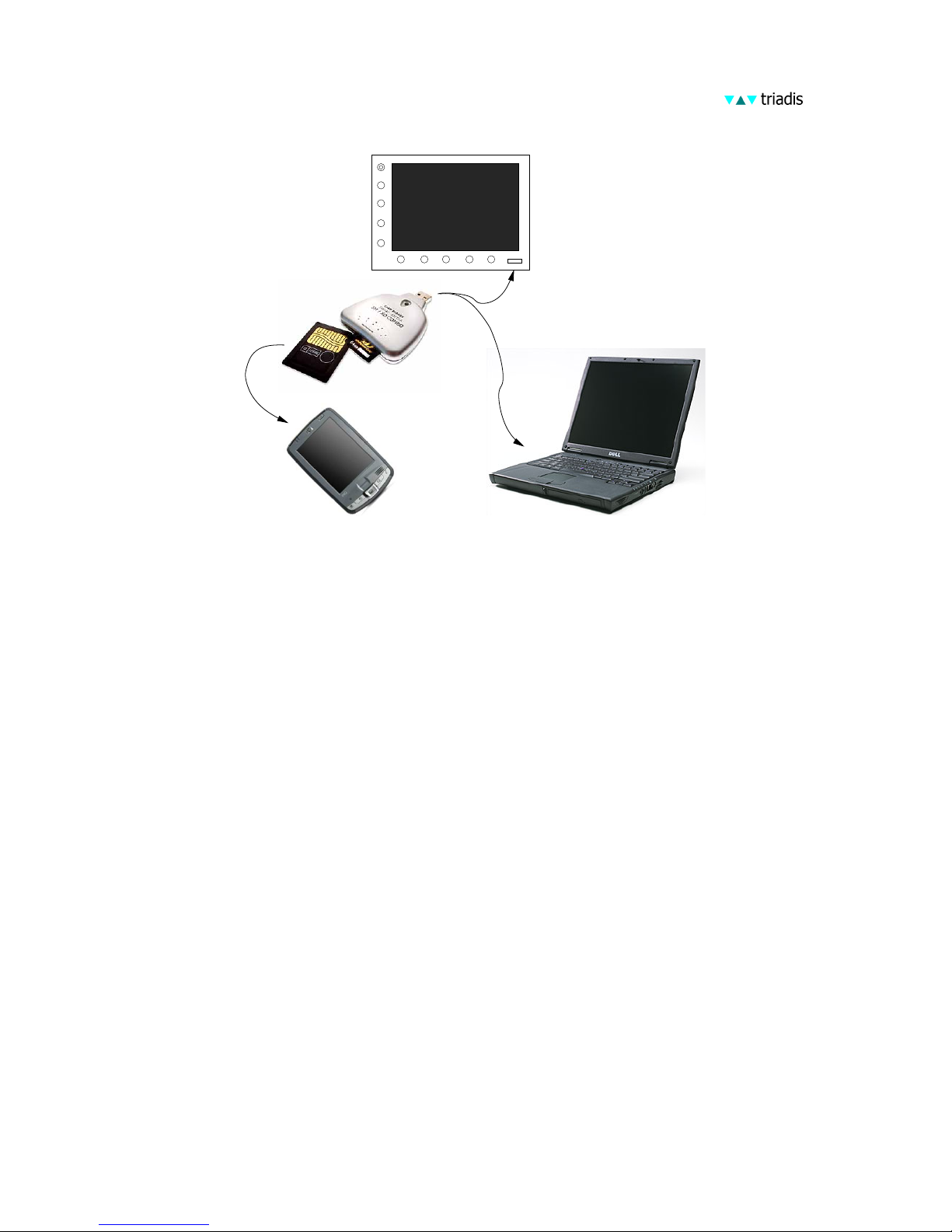
USB combo drive
MMC card
SD card
DISP
CFG
INFO
NAV
PWR
Computer
PDA
Altair
4.2 Preparation of USB memory stick
To perform software and database updates and to download files
from Altair to the USB memory stick, follow the instructions below:
• First prepare the USB memory stick (usually this only has
to be performed once).
• Create a directory on the USB memory stick
\ToAltair
Place any files for installation in that directory. Only files
required by XCSoar or Altair are uploaded, files of unknown
formats are ignored. The directory name is case sensitive.
• Create a directory on the USB memory stick
\FromAltair
Files downloaded from Altair will be copied into this directory if it exists. If the directory does not exist, no downloads
will be performed. The directory name is case sensitive.
The XCSoar program as well as AltairSync itself can be upgraded.
The proper file name convention for these files are:
XCSoarAltair-YYY-CRCZZ.exe
28

and
AltairSync-YYY-CRCZZ.exe
where YYY is a three digit version number, ZZ is a two digit hex
number representing a data integrity check sum, the value of which
will differ between different software versions.
4.3 Running AltairSync
• Turn off Altair.
• Insert the USB memory stick in the slot on the instrument
face.
• Turn on Altair.
• When Altair starts up, it will run the AltairSync utility.
This will copy all files in the ToAltair directory to Altair.
It will also copy data and configuration files (flight logs .igc,
profiles .prf) to the FromAltair directory on the USB memory stick.
• If AltairSync detects that the storage memory on Altair is
low, it issues a warning and allows the user to select old files
to be deleted. After freeing up storage memory, the new files
can be installed.
Both upload and download is performed automatically and only
requires user intervention to confirm overwriting existing files etc.
Note: it is important to not turn Altair off while AltairSync is running, as doing so might leave corrupted files on the device. Special
29

care must be taken when installing upgrades to the XCSoar and
AltairSync programs. Should a corrupted file transfer take place
and if AltairSync is unable to recover, Altair may be rendered inoperable and require repair by an technician authorised by Triadis
Engineering.
When the AltairSync and XCSoar programs are being updated,
the utility performs CRC error checking on the file transfer; in
the event of failure, the system reverts to the old version of the
program.
After new files are installed or if old files are removed, the configuration of XCSoar may need to be adjusted. This can be accessed
via the menu:
CONFIG . Setup system
When uploading files from the USB stick to Altair, the user is
asked whether files on the USB stick should be deleted after a
successful upload.
4.4 Cleaning old files
AltairSync will start on power-on if Altair detects that the storage
memory is nearly full, in order to allow the user to clean up old
files to free up space on the device. If the USB memory stick is
inserted at start up but the user declines to perform upload when
asked, it will then ask if the user wants to enter the file cleanup
mode.
When file uploads are being performed, if the system detects that
there is insufficient storage to complete the transfer, then this too
will cause the system to enter the file cleanup mode.
30

The file browser dialog shows a list of files that may be candidates for deletion. The dialog also shows the current free storage
memory.
There is a filter to allow the selection of different types of files,
including:
1. Flight logs (.igc)
2. Data logs (.log)
3. Tasks (.tsk)
4. Profiles (.prf)
5. Programs (.exe)
6. Audio (.wav)
7. Data files (.dat)
8. Text files (.txt)
9. Topology files (.tpl)
10. All (*)
After changing the filter, press the ‘Refresh’ button to scan the
system for matching files.
Important system files used by Altair and XCSoar are hidden from
view and so cannot be accidentally deleted.
Press the Close button when finished with file browsing/deleting.
If the file browser was initiated in response to the system determining insufficient free storage to complete a file transfer, and there is
still insufficient free storage, then the user will be asked whether
to return to the file browser or cancel the file transfer.
31

Support for automatic compression and cleaning of old log files is
planned for a future release of AltairSync.
4.5 Obtaining updated software and databases
Altair runs a special version of XCSoar and updates for both XCSoar and AltairSync will primarily be distributed through the Triadis Engineering website at
http://www.triadis.ch
XCSoar updates may be provided through other websites such as
the home site of XCSoar at
http://xcsoar.sourceforge.net
although these versions are not officially approved by Triadis Engineering and users may only install them at their own risk.
Data file updates distributed through the XCSoar website are approved; however it remains the owner’s responsibility at all times
to ensure that the files installed on Altair are up to date and accurate.
32

Appendix A Feature summary
Notes:
: Feature available only in PRO version
† : Internal logger IGC certification pending
Design overview
• Large, sunlight readable display with automatic back light
• Low power drain
• USB host, to allow connection with USB storage drives for
easy transfer of flight logs and applying software or data file
updates.
• Lightweight, small and affordable
• High performance GPS receiver with external antenna
• Battery backup allows system to keep running even with
glider’s battery depleted
Software
• XCSoar glide computer software
• Open source, actively maintained
• Simple to use, yet extremely powerful
• Field-proven
• Designed for competitive as well as casual cross-country fly-
ing.
User Interface
• 10 buttons for quick-access functions and menu navigation
for accessing other functions
• Dual rotary knob with push button select, for controlling a
cursor
• Support for external switches, controls and other devices via
1-Wire interface.
• A control stick grip with switches to control the glide computer is available as an accessory
33

Moving map display
• Terrain and topological features
• Terrain shaded by sun direction or lift-generating slope
• Arrival altitude of landable points
• Shows reachable glide footprint
• Auto-zoom and separate climb/cruise zoom levels
• Orientation can be selected from north-up, track-up, north-
up when circling, track-up when circling.
• Markers can be dropped manually or automatically.
• Display of airspace areas.
• Query of airspace and waypoints by pointing on the map
display.
• Airfield details include Enroute Supplement information and
satellite images.
• Quick toggle between full screen and instrument/infobox
display modes
• Display of FLARM traffic on the map and in short-range
‘radar’ window
Display symbols and annunciators
• Wind speed and direction.
• Bearing and optimal cruise track to next waypoint
• Estimated glider heading adjusted for wind
• Flight mode icons (circling, cruise, final glide)
• GPS/FLARM/Logger status icons
• Altitude required to complete task
• Thermal profile display
• Speed command chevrons
• Compass indicator
• Variometer needle with climb trend
• Large selection from over 50 items of information displayed
in InfoBoxes.
• Separate InfoBox layouts in circling, cruise, final glide flight
modes. Separate InfoBox layout for auxiliary display mode
accessible from any flight mode.
• Display of glider trail, color and thickness scaled to climb
rate.
• Dropped markers, thermal markers.
34

Glide computer
• Calculation of height required around task
• Final glide through terrain and around multiple waypoints
• Final glide adjusted for kinetic energy
• Detection of nearby airspace, recommended vector to exit
airspace
• Bugs and ballast settings
• Custom glide polars
• Integration with intelligent variometer
• MacCready theory with adjustments for risk
• Auto-MacCready
• Estimated arrival times
Task planning and management
• Waypoints sorted by name or distance and direction
• Full support for Assigned Area Tasks, FAI tasks and custom
competition rules
• Allows tasks to be aborted/resumed; in abort mode, the glider
is directed to the nearest landing options.
• Task declaration sent to external logger.
• Internal software based (non-approved) IGC logger, useful
as backup.
IGC logger†
• A sealed, secure IGC logger module is available as an option
• Supports latest IGC standard including FLARM data
• Integrated barometer, and microphone for engine noise de-
tection
Analysis and statistics
• Climb statistics, trends
• Wind at altitude
• Glide polar diagram
• Barograph trace, trends
• Task performance
• Convection and cloud forecast
• Status page reports range and bearing to nearest landmark
35

Customisation
• Multiple language support (English, German, Italian, etc)
• Menu system can be modified or extended
• Buttons can be reassigned to alternate functions
• Glide computer events, button events and external switches
can be assigned to trigger functions in the computer or display.
• All data formats are public so users can modify or generate
their own data files.
• Orientation in landscape or portrait mode
• Custom display themes with fonts, colors, icons
• Pilots can select their name from a list to choose their indi-
vidual settings.
External device integration
• Connects to intelligent variometers to receive airdata measurements, and to synchronise MacCready, bugs, ballast and
cruise/climb mode settings.
• Instrument calibration and fine tuning
• FLARM ready
• On-screen selection of radio transceiver frequency (when
connected to supported aircraft radio).
• (External devices not included)
36

Appendix B Technical specifications
Mechanical
Dimensions : 147 x 117 x 23 mm
Weight : 460 g (Altair Standard), 510 g (Altair Pro), Wiring harness
50 g, 1m patch cable 50 g, GPS antenna 70 g.
Mount : Instrument panel via four screws, direct to instrument panel
or via mounting brackets
Computer
CPU : Intel XScale PXA270 at 325 MHz
Memory (RAM) : 64 Mb
Memory (Storage) : 32 Mb, approximately 8 Mb available to user
Operating system : Windows Mobile 5.0
Display
Dimensions : 5.7 inch (145 mm) diagonal
Resolution : 320x240 pixels
Technology : Transmissive LCD, 18 bit colour, with back light and auto-
matic brightness adjustment
Audio signals
Audio output : Stereo unamplified
Internal Speaker : Piezoelectric buzzer
Configuration
Software configuration : On-screen, built into XCSoar software
File updates : By USB memory stick using AltairSync software
Software upgrade : By USB memory stick using AltairSync software
Interface
Protocol : NMEA-0813 with proprietary extensions
37

Serial comms : RS-232 38400 baud, 8N1
USB host : USB 2.0, Type A
Peripheral bus : Dallas Semiconductor 1-Wire bus
Power Supply
Operating Voltage : 12V DC (8 − 16) V DC
Consumption : 275 mA typical at minimum back light, 500 mA typical at
full back light, 250 mA additional when charging backup
battery
Battery backup : Li-Ion, up to one hour endurance
Altair has over-voltage protection which disconnects the device
from the power source if the input voltage exceeds 16V. Input voltage over 30V will blow the internal fuse. Altair is reverse voltage
protected up to -30V.
Environmental
Temperature range : -30 to +65 degrees C
Humidity : 10-90% non-condensing
Shock resistance : not specified
Vibration resistance : not specified
38

Appendix C Panel mount
Exterior dimensions: 147 x 117 x 23 mm.
Dimensions (front)
NOT TO SCALE
39

Dimensions (rear)
NOT TO SCALE
40

Mounting bracket configurations
41

Appendix D Electrical connectors
All connectors are shown from the perspective of looking at the
connector on the back of the instrument.
D.1 Main connectors
Power and data port
Connector X1
Type : D-Sub 15pin high density male
6,11 : 12V Supply in (install 2.5A fuse)
5,7,8,9 : Supply ground
2 : Primary RS232 TX, Data sent from Altair
3 : Primary RS232 RX, Data received by Altair
4 : Secondary RS232 TX, Data sent from Altair
1 : Secondary RS232 RX, Data received by Altair
12 : Supply external devices (switched)
13 : 1-Wire peripheral bus signal
10 : Audio Signal ground
14 : Audio out left (unamplified)
15 : Audio out right (unamplified)
GPS antenna port
Type: FAKRA SMA antenna connector
42

D.2 Wiring harness
Connector X2: Power terminal
Type : WAGO 733 Cage Clamp terminal
1 : 12V Supply in (install 2.5A fuse)
2 : Supply ground
3 : Switched 12V out to supply external devices (such as Vega
or FLARM)
4 : Supply ground (used as external supply return)
5 : 1-Wire peripheral bus signal
6 : Supply ground (used as 1-Wire bus ground)
Note : Use the operating tool supplied to open the spring clamp.
Connector X3: Mixed signal
Type : WAGO 733 Cage Clamp terminal
1 : Supply ground (used as RS232 ground return)
2 : Primary RS232 TX, Data sent from Altair
3 : Primary RS232 RX, Data received by Altair
4 : Audio out left (unamplified)
5 : Audio Signal ground
6 : Audio out right (unamplified)
Note : Use the operating tool supplied to open the spring clamp.
Connector X4: Primary data port
Pins numbered from right to left when viewing socket pins down.
Note that according to the IGC specifications, the connector is
numbered the other way around (e.g. 7,8 GND).
Note : Connect your intelligent variometer to this port
43

Type : RJ45, IGC Layout RX/TX Crossover
1,2 : GND, external device GND
3 : RS232 TX, Data sent from Altair
4 : RS232 RX, Data received by Altair
5,6 : Not connected
7,8 : 12V, External device supply, DO NOT feed in power to this
Pin!
Connector X5: Secondary data port
Pins numbered from right to left when viewing socket pins down.
Note that according to the IGC specifications, the connector is
numbered the other way around (e.g. 7,8 GND).
Description : Secondary data port
Type : RJ45, IGC layout
1,2 : GND, External device GND
3 : RS232 RX, Data received by Altair
4 : RS232 TX, Data sent from Altair
5,6 : Not connected
7,8 : 12V, External device supply, DO NOT feed in power to this
Pin!
44

Appendix E Limited Warranty
Triadis Engineering GmbH (triadis) guarantees you as the initial
buyer that the product is free from manufacturing and material
defects in normal use, for a period of twelve months starting from
sales date, provided that it was unused at the time of the purchase.
Returns must be made within the guarantee period, and must be
well packed, together with your name, your address, telephone
number, a statement describing the problem with the product, and
a copy of the original invoice from the store where the device was
originally purchased. The customer is responsible for any possible
loss or damage of the product during transport. triadis commits
itself under this warranty only to repair or replace the defective
product or parts thereof which are deemed to have failed within
the guarantee period area at the discretion of triadis.
triadis is not obligated to rep air or replace the product, if according to opinion of triadis: (A) the failure of the product is to be
attributed to accident, abuse, misuse, carelessness, improper modification or repair; or (B) the product was not installed or operated
in accordance with the instructions of triadis; or (C) the failure
is attributed to normal wear; or (D) the customer did not follow
its obligations in accordance with the conditions specified above.
If the examination of any requirement, which is raised under this
warranty, results in the fact that it lies outside of the permissible
period or warranty extent or the product is not found to be defective, the costs of such an examination and/or repair will be debited
to the customer.
Any descriptions, designs, specifications, samples, models, reports
or similar material, which are published in connection with the
sales of the product, cannot be regarded as an expression of warranty that the product corresponds to or will fulfil the requirements
of the customer.
45

Appendix F Reference Card
Rotary knob
Mode Outer ring Inner ring Button
Default Zoom in/out unassigned Ack message/airspace
Dialogs Cursor previous/next Adjust value Select item
Lists Cursor up/down Cursor up/down page Select item
Pan Move up/down Move left/right unassigned
Power/esc button
Mode LED Button
Power off Dark Press to power on
Power on Lit Press 5 seconds to power off
Menu Press quickly to cancel menu
Dialog Press quickly to cancel/escape
46

Menus and function/select buttons
Menu mode F6 F7 F8 F9 F0
Default
Pan
On
Zoom
in
Zoom
out
Drop
marker
Arm
advance
Pan
Pan
Off
Zoom
in
Zoom
out
Nearest
waypoint
NAV Task
calc
Arm
advance
Waypoint
previous
Waypoint
next
Waypoint
lookup
Task
edit
Task
save
Task
abort
Force
final
Team
code
DISPLAY Pan
On
Zoom
in
Zoom
out
Mark
drop
Fullscreen
toggle
Zoom
auto
Snail
trail
Terrain
toggle
Bright Declutter
Labels
CONFIG MacCready+MacCready-MacCready
auto
Setup
Basic
Wind
Vario/ Setup
system
Settings
airspace
Logger
Record
Logger
Replay
INFO Waypoint
details
Nearest
waypoint
Nearest
airspace
Check
list
Analysis
Status
system
Status
aircraft
Status
task
Aux
infobox
Message
repeat
Vario Airframe
Switches
Setup
Audio
Manual
Demo
Setup
Stall
ASI
Zero
Accel
Zero
Store Cruise
Demo
Climb
Demo
47

Notes
48
 Loading...