

Page 1
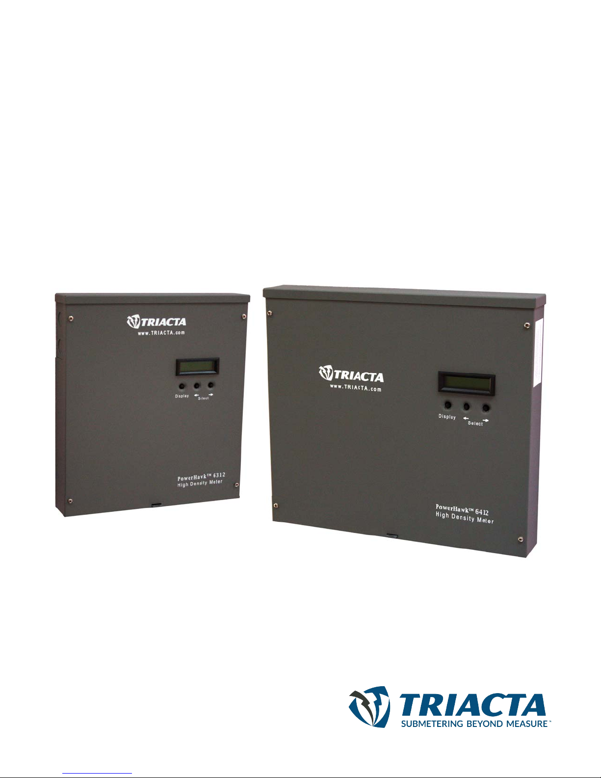
PowerHawk 6212, 6312 and 6412 meters
High Density Meters
Installation Guide
Page 2
PowerHawk 6212, 6312 and 6412 meters 930-108-01-A.04
DANGER
WARNING
01/2011
Hazard Categories and Special
Symbols
Read these instructions carefully and look at the equipment to become
familiar with the device before trying to install, operate, service or maintain
it. The following special messages may appear throughout this bulletin or on
the equipment to warn of potential hazards or to call attention to information
that clarifies or simplifies a procedure.
The addition of either symbol to a “Danger” or “Warning” safety label
indicates that an electrical hazard exists which will result in personal injury if
the instructions are not followed.
This is the safety alert symbol. It is used to alert you to potential personal
injury hazards. Obey all safety messages that follow this symbol to avoid
possible injury or death.
DANGER indicates an imminently hazardous situation which, if not
avoided, will result in death or serious injury.
WARNING indicates a potentially hazardous situation which, if not
avoided, can result in death or serious injury.
CAUTION
CAUTION indicates a potentially hazardous situation which, if not
avoided, can result in minor or moderate injury.
CAUTION
CAUTION, used without the safety alert symbol, indicates a potentially
hazardous situation which, if not avoided, can result in property damage.
NOTE: Provides additional information to clarify or simplify a
procedure.
PLEASE NOTE Electrical equipment should be installed, operated, serviced, and
FCC NOTICE This equipment has been tested and found to comply with the limits
maintained only by qualified personnel. No responsibility is assumed
by Triacta for any consequences arising out of the use of this
material.
for a Class A digital device, pursuant to part 15 of the FCC Rules.
These limits are designed to provide reasonable protection against
harmful interference when the equipment is operated in a commercial
environment. This equipment generates, uses, and can radiate r adio
frequency energy and, if not installed and used in accordance with
the instruction manual, may cause harmful interference to radio
communications. Operation of this equipment in a residential area is
likely to cause harmful interference in which case the user will be
required to correct the interference at his o wn expense. This Class A
digital apparatus complies with Canadian ICES-0 03 .
© 2011 Triacta Power Technologies All Rights Reserved
Page 3

930-108-01-A.04 PowerHawk 6212, 6312 and 6412 meters
01/2011
INDUSTRY CANADA CLASS A EMISSION
COMPLIANCE STATEMENT
This equipment does not exceed the Class A limits for radio noise
emissions from digital apparatus as set out in the radio interference
regulations of the Canadian ICES-003.
Avis de conformité aux normes d'Industrie Canada. Cet appareil
numérique de la classe A est conforme
à la norme NMB-003 du
Canada.
TUV AND UL TUV Rheinland of North America and UL (Underwriters Lab oratories)
are listed by the American Federal Occupational Safety an d Healt h
Administration (OSHA) under NRTL (Nationally Recognized Testing
Laboratory) program. They are also accredited by Sta ndards Council
of Canada. This equipment complies with UL 61010-1 Second
Edition and CSA C22.2 No. 61010-1-04.
© 2011 Triacta Power Technologies All Rights Reserved
Page 4

PowerHawk 6212, 6312 and 6412 meters 930-108-01-A.04
01/2011
© 2011 Triacta Power Technologies All Rights Reserved
Page 5

930-108-01-A.04 PowerHawk 6212, 6312 and 6412 meters
01/2011 Table of Contents
Table of Contents
INTRODUCTION .........................................................................................1
System Description .....................................................................................1
PowerHawk 6212, 6312 and 6412 System Specifications .................... 1
SAFETY PRECAUTIONS.................................... .................................. ... ...6
Electrical Safety Compliance .................................................................6
INSTALLATION...........................................................................................7
Pre-Installation ............................................................................................ 7
Receiving ...............................................................................................7
Pre-Installation Checklist .......................................................................7
Site Planning .........................................................................................8
Installation Procedures ............................ ... ................................................8
Mounting the PowerHawk 6212, 6312 and 6412 meters ...................... 9
Installing Voltage Transformers for Three-Phase Service Greater Than
120V ....................................................................................................10
Installing the Current Transformers .....................................................15
Connecting the Communications ........................................................22
Start-Up Sequence .................................................... ... .......................22
Pulse Inputs .........................................................................................23
Display Navigation ...............................................................................23
Recording the Meter Map ....................................................................24
MAINTENANCE ........................................................................................26
Fuse Replacement ....................................................................................26
REGULATORY COMPLIANCE.................................................................27
Equipment servicing and access .........................................................27
USER NOTES...................................... .. .................................. ..................31
© 2011 Triacta Power Technologies All Rights Reserved
i
Page 6

PowerHawk 6212, 6312 and 6412 meters 930-108-01-A.04
Table of Contents 01/2011
© 2011 Triacta Power Technologies All Rights Reservedii
Page 7

930-108-01-A.04 PowerHawk 6212, 6312 and 6412 meters
01/2011 Introduction
INTRODUCTION This document describes the PowerHawk 6212, 6312 and 6412 meters,
including procedures to install and start up the unit, and complete the initial
configuration:
• “System Description” on page 1
• “Pre-Installation” on page 7
• “Installation Procedures” on page 8
• “Start-Up Sequence” on page 22
• “Fuse Replacement” on page 26
This documentation is intended for those responsible for installing and
configuring the PowerHawk 6212, 6312 and 6412 meters. Installers must be
qualified electricians with knowledge of local and national code
requirements. See “Safety Precautions” on page 6.
System Description The PowerHawk 6212, 6312 and 6412 meters support:
• single-phase, 2-wire
• single-phase, 3-wire (network)
• three-phase devices
Depending on how the meters are installed and configured, they can meter
8, 12, or 24 individual meter points. The PowerHawk 6212, 6312 and 6412
meters are designed for residential, commercial, and industrial use and
display the power and consumption readings for each measurement point.
PowerHawk 6212, 6312 and 6412 System
Specifications
The PowerHawk 6212, 6312 and 6412 system architecture includes:
• single-phase, 2-wire; single-phase, 3-wire (network); and three-phase
compatibility
• 120/208V and 120/240V configurations
• 8, 12, or 24 individual meter points
• local Ethernet configuration interface via PC and web browser
• on-board modem and Ethernet ports for remote reporting
• RS232 serial port for external display
• 2 pulse inputs to connect metering devices
Table 1 lists the system specifications of the PowerHawk 6212, 6312 and
6412 meters.
© 2011 Triacta Power Technologies All Rights Reserved
1
Page 8

PowerHawk 6212, 6312 and 6412 meters 930-108-01-A.04
Introduction 01/2011
Table 1: PowerHawk 6212, 6312 and 6412 meter specifications
Specification PowerHawk 6212 meter PowerHawk 6312 meter PowerHawk 6412 meter
Dimensions Height: 13.125 in. (33.5 cm)
Weight 8.77 lb (3.98 kg) 8.77 lb (3.98 kg) 11.9 lb (5.4 kg)
Reference input voltage 208Y/120V, 3W+N+Protective Earth
Reference voltage
tolerance
Supply voltage and current North America: 120V 125 mA 60 Hz
Current transformers
Measurement Category III
Measurement accuracy ANSI C12.20 Measurement Canada Approved
Pulse inputs 1 and 2 Dry form A and solid-state form A
Non-volatile memory
storage
Onboard modem V.90 V.90 V.90
Onboard Ethernet port 10/100 Mb/s 10/100 Mb/s 10/100 Mb/s
Width: 12 in. (30.5 cm)
Depth: 2.125 in. (5.5 cm)
208Y/120V, 2W+N+Protective Earth
120/240V, 2W+N+Protective Earth
+/-10% +/-10% +/-10%
International: 230-240V 63 mA 50/60
Hz
0.333 V secondary CT
Note: All CTs used with the product
must be UL recognized/listed.
compatible
Maximum frequency 10 Hz
Minimum pulse width 20 ms
120 days in 15-minute intervals 120 days in 15-minute intervals 120 days in 15-minute intervals
Height: 13.125 in. (33.5 cm)
Width: 12 in. (30.5 cm)
Depth: 2.125 in. (5.5 cm)
208Y/120V, 3W+N+Protective Earth
208Y/120V, 2W+N+Protective Earth
120/240V, 2W+N+Protective Earth
North America: 120V 125 mA 60 Hz
International: 230-240V 63 mA 50/60
Hz
80 mA secondary CT
200 A primary CT
Triacta part number 900-313-00
Model 7896
Note: All CTs used with the product
must be UL recognized/listed.
EG07 compliant
Dry form A and solid-state form A
compatible
Maximum frequency 10 Hz
Minimum pulse width 20 ms
Height: 13.125 in. (33.5 cm)
Width: 17 in. (44 cm)
Depth: 2.125 in. (5.5 cm)
208Y/120V, 3W+N+Protective Earth
208Y/120V, 2W+N+Protective Earth
120/240V, 2W+N+Protective Earth
North America: 120V 125 mA 60 Hz
International: 230-240V 63 mA 50/60
Hz
5 A secondary CT
Note: All CTs used with the product
must be UL recognized/listed.
Measurement Canada Approved
EG07 compliant
Dry form A and solid-state form A
compatible
Maximum frequency 10 Hz
Minimum pulse width 20 ms
Serial port 115 kb/s 115 kb/s 115 kb/s
Fuse rating (F1) North America:120V: T125 mA, 250V
International 230V: T63 mA, 250V
North America:120V: T125 mA, 250V
International 230V: T63 mA, 250V
North America:120V: T125 mA, 250V
International 230V: T63 mA, 250V
Environmental
Operating temperature -40 to 70oC -40 to 70oC -40 to 70oC
Operating humidity 0 to 90% non-condensing 0 to 90% non-condensing 0 to 90% non-condensing
Usage environment Indoor or enclosed outdoor
Maximum altitude 6562 ft (2000 m) 6562 ft (2000 m) 6562 ft (2000 m)
Pollution degree 2 2 2
environment
Indoor or enclosed outdoor
environment
Indoor or enclosed outdoor
environment
© 2011 Triacta Power Technologies All Rights Reserved2
Page 9
930-108-01-A.04 PowerHawk 6212, 6312 and 6412 meters
Display
PowerHawk 6312
High Density Meter
www.TRIACTA.com
TM
Select
01/2011 Introduction
Front Panel Display
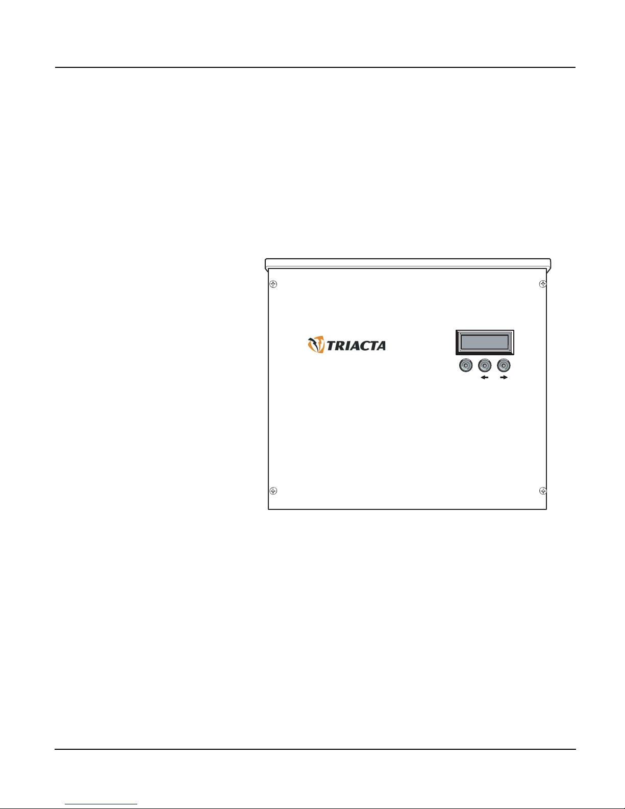
The PowerHawk 6212, 6312 and 6412 meters have the following front panel
features (Figure 1 shows the PowerHawk 6312 front panel):
• LCD — displays 2 rows of 16 characters for each of the meter points
(8, 12, or 24)
• Display button — cycles through the available information for each of
the meter points
• Left and right arrow buttons — selects which of the meter points is
on the display
Figure 1: PowerHawk 6312 front panel
© 2011 Triacta Power Technologies All Rights Reserved
3
Page 10
PowerHawk 6212, 6312 and 6412 meters 930-108-01-A.04
Earth Stud
Power Input
Terminal Block
Auxilliary
Power Input
Connector
Fuse
Ingress
Punch-outs
Mounting
Keyhole
Display
Modem Port
Serial RS232
Ethernet Port
Pulse In
Terminal Blocks
Pulse Out
Connector
Meter Point
Input Connector
Cover Screw
Location
Cover Screw
Location
Cover Screw
Location
Cover Screw
Location
Introduction 01/2011
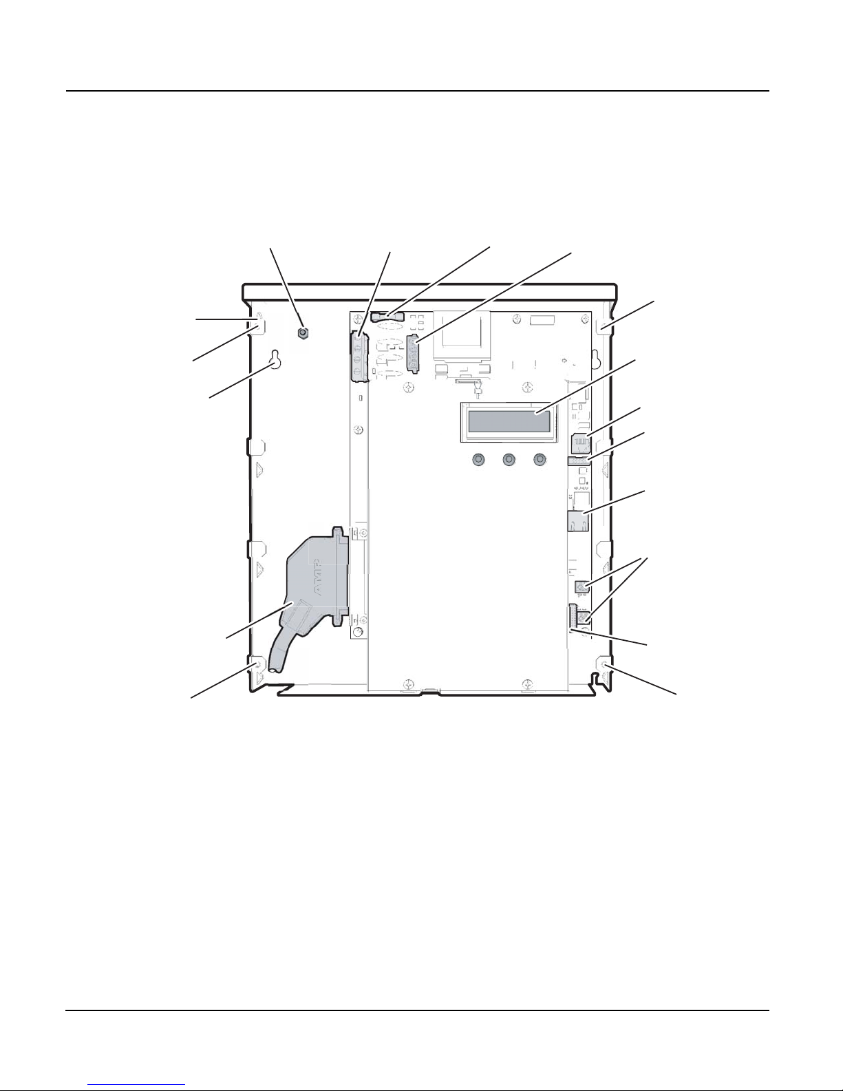
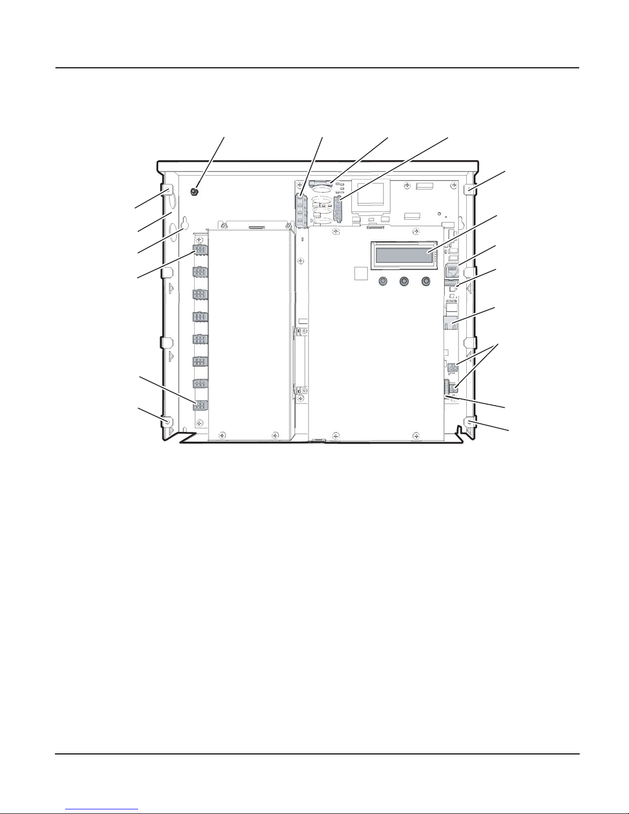
Figure 2 shows the internal view of thePowerHawk 6212 and PowerHawk
6312. See Figure 3 for the internal view of the and PowerHawk 6412.
Figure 2: PowerHawk 6212 and PowerHawk 6312 internal view
© 2011 Triacta Power Technologies All Rights Reserved4
Page 11
930-108-01-A.04 PowerHawk 6212, 6312 and 6412 meters
Earth Stud
Power Input
Terminal Block
Auxilliary
Power Input
Connector
Fuse
Ingress
Punch-outs
Mounting
Keyhole
Meter Point
Input (JM1)
Meter Point
Input (JM8)
Display
Modem Port
Serial RS232
Ethernet Port
Pulse In
Terminal Blocks
Pulse Out
Connector
Cover Screw
Location
Cover Screw
Location
Cover Screw
Location
Cover Screw
Location
01/2011 Introduction
Figure 3: PowerHawk 6412 internal view
© 2011 Triacta Power Technologies All Rights Reserved
5
Page 12

PowerHawk 6212, 6312 and 6412 meters 930-108-01-A.04
DANGER
Safety Precautions 01/2011
SAFETY PRECAUTIONS Carefully observe these safety instructions.
HAZARD OF ELECTRIC SHOCK, EXPLOSION, OR ARC FLASH
• Apply appropriate personal protective equipment (PPE) and follow
safe electrical work practices. See NFPA 70E.
• Only qualified electrical workers should install this equipment. Such
work should be performed only after reading this entire set of
instructions.
• The equipment must be accessible to authorized personnel only.
Equipment must be installed in areas where access can be
restricted.
• NEVER work alone.
• Before performing visual inspections, tests, or maintenance of this
equipment, disconnect all sources of electric power. Assume that all
circuits are live until they have been completely de-energized,
tested, and tagged. Pay particular attention to the design of the
power system. Consider all sources of power, including the
possibility of backfeeding.
• Turn off all power supplying the meter and the equipment in which
it is installed before working on it.
• Always use a properly rated voltage sensing device to confirm that
all power is off.
• Do not touch enclosure when equipment is running in 60
greater ambient temperature.
• Before closing all covers and doors, carefully inspect the work area
for tools and objects that may have been left inside the equipment.
• Successful equipment operation requires proper handling,
installation, and operation. Neglecting fundamental install ation
requirements can lead to personal injury as well as damage to
electrical equipment or other property.
• NEVER bypass external fusing.
• NEVER short the secondary of a Voltage Transformer (VT).
• Always short the secondary of a current transformer prior to
disconnecting current input loads.
Failure to follow these instructions will result in death or serious
injury.
o
C or
Electrical Safety Compliance • Use the unit only in accordance with the electrical power rating
• The unit is only to be installed by a qualified electrician
• Initial installation of the unit must be inspected by the local electrical
Inspection Authority
• Install the unit in compliance with the following local and national
electrical codes:
• Canada: Canadian Electrical Code, Part I, CSA C22.1
• United States: National Fire Protection Association (NFPA) 70; US
National Electrical Code
• Elsewhere: International Electrotechnical Commission (IEC) 364,
Part 1-7
• Ensure that the unit is properly earthed
• If the equipment is installed or used in a manner other than that
specified in this document, it may void your warranty or impair the
protection of the equipment.
© 2011 Triacta Power Technologies All Rights Reserved6
Page 13

930-108-01-A.04 PowerHawk 6212, 6312 and 6412 meters
01/2011 Installation
INSTALLATION This section contains the following installation topics:
• “Pre-Installation” on page 7
• “Installation Procedures” on page 8
• “Start-Up Sequence” on page 22
Pre-Installation The pre-installation checklist and site planning must be performed before
installing the equipment at the site.
Receiving The equipment required for each PowerHawk meter installation includes:
• high-density meter (PowerHawk 6212, PowerHawk 6312 or
PowerHawk 6412)
• For the PowerHawk 6212 and PowerHawk 6312, one 12-ft (4-m) AMP
cable with one 50-pin connector supplied with each unit
TM
• For the PowerHawk 6412, two Mate-n-Lok
supplied with each unit in 8-, 12-, or 24-connector variants
• CD and meter configuration software, this installation manual and an
installation record form
When you receive your order, verify that the items listed above are included
with the shipment, and visually inspect them for damage. If any parts are
missing or damaged, contact your Triacta representative.
wiring harnesses
Pre-Installation Checklist The installer must provide the following information, tools, and equipment
before proceeding with the installation:
• certified current transformers for metering (not supplied)
• an appropriate 20-Amp maximum circuit breaker or a fused disconnect
switch for the type of panel
• current/voltage meter to test the phasing of panels
• RJ45 Ethernet patch cable
2
• 4-wire 14 AWG (1.63 mm
circuits, or 3-wire 14 AWG (1.63 mm
) cable for three-phase wye connected
2
) cable for a single-phase wye
connected circuits
• small flat-head screwdriver
• #2 Phillips screwdriver
• crimping tool
• 18 AWG butt splice connector
• wire strippers
• four 1-inch (25 mm) #8 mounting screws suitable for selected mounting
surface
If using a modem, these items are also required:
• phone or butt set to test the phone line
• RJ11 junction box
• RJ11 splitter to tap into the existing junction box
• RJ11 patch cable
• xDSL filter if required (many businesses have their internet access on
the same line as the fax)
© 2011 Triacta Power Technologies All Rights Reserved
7
Page 14

PowerHawk 6212, 6312 and 6412 meters 930-108-01-A.04
Installation 01/2011
Site Planning 1. Determine the number of PowerHawk 6212, 6312 and 6412 meters to
be installed and ensure adequate space. For clearances, see Figure 4
on page 9.
2. Determine the number of analog phone lines or Ethernet drops
required, and ensure they are installed before installing the PowerHawk
6212, 6312 and 6412 meters. The recommended maximum number of
PowerHawk meters per phone line is 50.
3. Determine the number and types of meters or monitors required
(single-phase, network, or three-phase).
4. Determine the model number and correct input voltage based on the
voltage label on the top right side of the unit.
Access to Power and Lighting
The installation site must be supplied with access to the main electrical panel
and any sub-panels. Portable or permanent lighting must be available to
provide the installers with a clear view of the equipment and of the installation
environment. Each installation may vary depending on physical site
restrictions.
Installation Procedures This section provides information about activities that must be performed to
install the PowerHawk 6212, 6312 and 6412 meters in a single-phase 2-wire,
single-phase 3-wire (network), or three-phase 4-wire application (120/208V).
The installation procedures must be performed in the following order:
1. “Mounting the PowerHawk 6212, 6312 and 6412 meters” on page 9
2. “Installing Voltage Transformers for Three-Phase Service Greater Than
120V” on page 10
3. “Installing the Reference Voltage and Power Cable in a 120V
Application” on page 12
4. “Installing the Current Transformers” on page 15
5. “Connecting the Phone Line” on page 22
6. “Connecting the Ethernet Cable” on page 22
7. “Manually Testing Communications” on page 22
8. “Recording the Meter Map” on page 24
© 2011 Triacta Power Technologies All Rights Reserved8
Page 15
930-108-01-A.04 PowerHawk 6212, 6312 and 6412 meters
11.0 in
27.9 cm
(6312)
10.67in
27.1cm
6in
15.2 cm
6.0 in
15.2 cm
4
1
2
1
1
1
2
2
2
3
Legend:
1 Mounting keyhole
2 Cover screw location
3 Electrical distribution panel
4 CT conduit
5 Power conduit
5
01/2011 Installation
Mounting the PowerHawk 6212, 6312 and
6412 meters
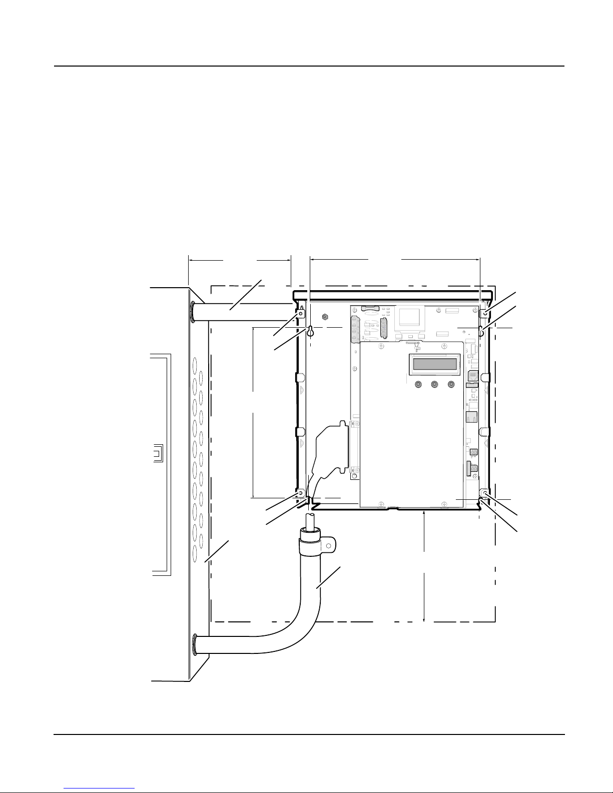
Mount the PowerHawk 6212, 6312 and 6412 meters adjacent to the main
circuit breaker box using the 1-inch (25-mm) #8 screws as shown in Figure
4. If mounting the unit on a plasterboard surface, use cylinder plugs.
1. Remove the front cover from the meter by removing the four screws
with a #2 Phillips screwdriver. Retain the cover and screws for later
re-installation.
2. Mount the PowerHawk meter on the wall and secure it by inserting a
screw in each mounting keyhole and tightening the screws.
Figure 4: Mounting Dimensions and Clearances
© 2011 Triacta Power Technologies All Rights Reserved
9
Page 16
PowerHawk 6212, 6312 and 6412 meters 930-108-01-A.04
To PowerHawk
From Breaker Panel
Installation 01/2011
Installing Voltage Transformers for
Three-Phase Service Greater Than 120V
Voltage transformers are required when metering services greater than 120V
to reduce the line-to-neutral voltage of the service to 120V. The accuracy
class should be 0.3% or better, with a burden rating of 30VA.
For applications in Canada, Measurement Canada approved voltage
transformers are required. Measurement Canada requires an accuracy class
of 0.3% or better, with a 150VA rating.
NOTE: Voltage transformer burden depends on the control power
source. If control power is provided separately (not derived from the
metered voltage), then lower transformer burden may be acceptable.
Contact your local Triacta representative for details.
Voltage transformers must be mounted in a listed electrical enclosure. Mount
the voltage transformer enclosure between the supply voltage and the
PowerHawk 6212, 6312 and 6412 meters. Transformer configuration must
be Y||Y (wye-wye).
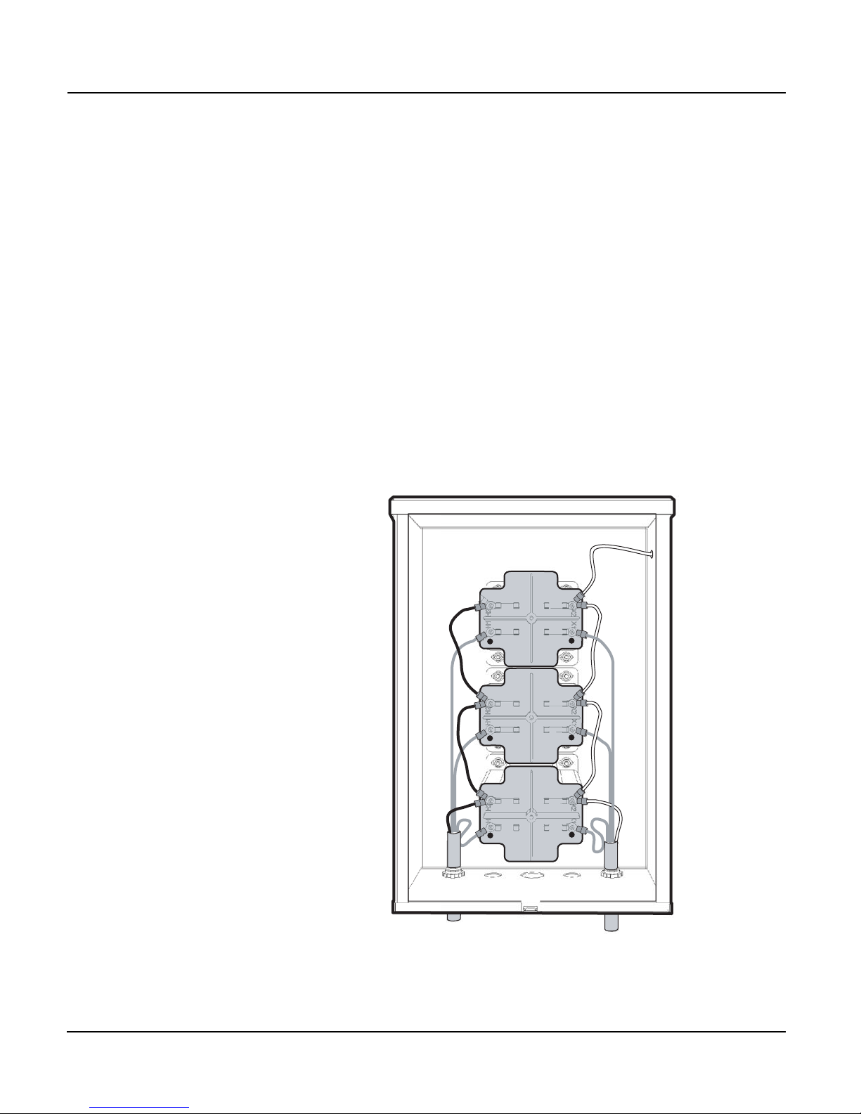
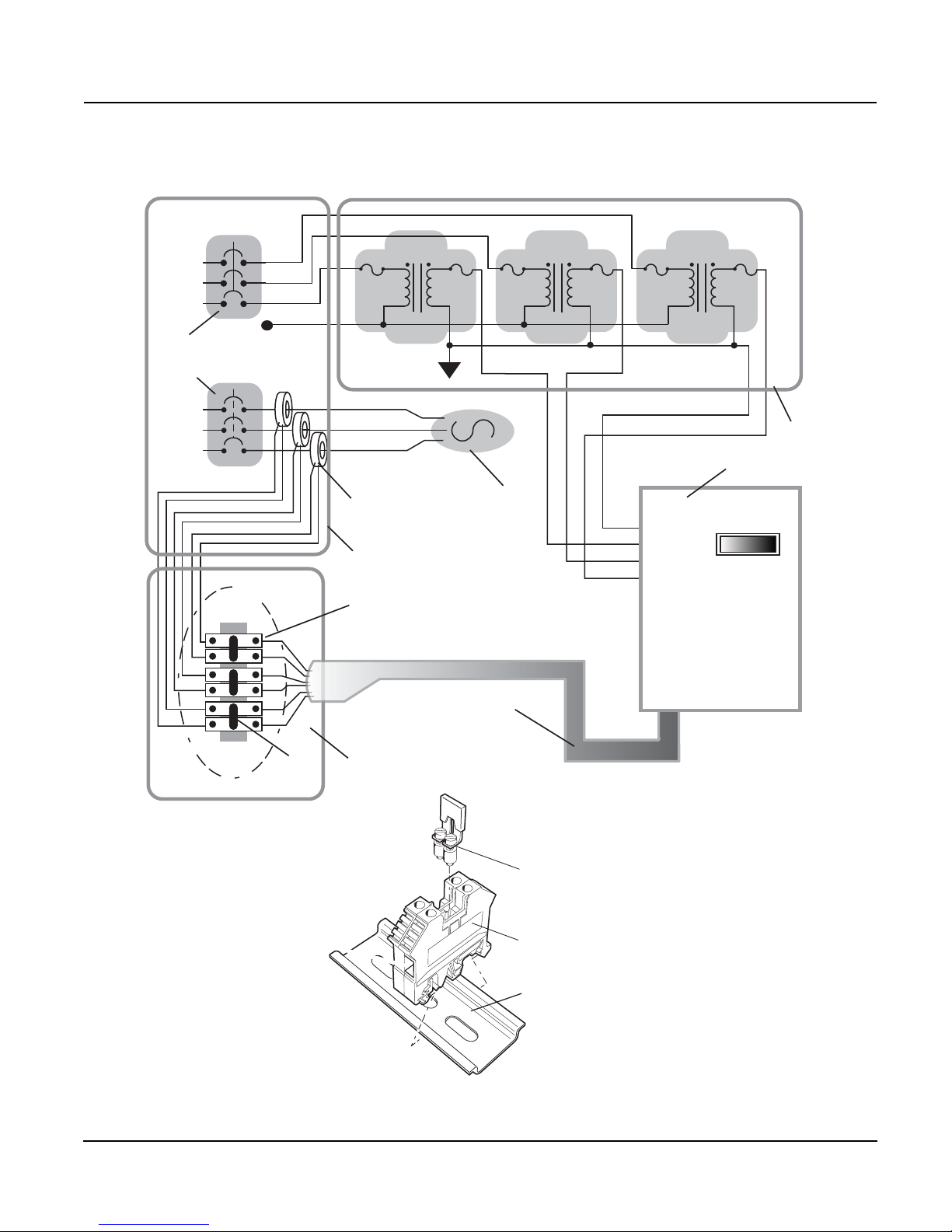
Figure 5 shows a voltage transformer chassis in a three-phase 277/480V
installation . Figure 6 shows a block diagram of a complete three-phase 480V
installation.
Figure 5: Voltage transformer chassis
© 2011 Triacta Power Technologies All Rights Reserved10
Page 17
930-108-01-A.04 PowerHawk 6212, 6312 and 6412 meters
H1
X1
H2 X2
H1
X1
H2 X2
H1
X1
H2 X2
C
B
A
N
N
A
B
C
1
2
3
4
12
Z
5
6
7
8
13
11
12
Shorting block detail
10
9
Legend:
1 Shorting block enclosure
2 Shorting block
3 Breaker panel
4 Current transformer
5 Load breaker
6 Meter breaker
7 Transformer enclosure
8 PowerHawk meter
9 Load
10 Cable
11 Shorting jumper
12 Shorting block
13 DIN rail
01/2011 Installation
Figure 6: Typical three-phase 480V installation
© 2011 Triacta Power Technologies All Rights Reserved
11
Page 18
PowerHawk 6212, 6312 and 6412 meters 930-108-01-A.04
DANGER
Installation 01/2011
Installing the Reference Voltage and Power Cable in a 120V Application
The reference voltage (A, B, C, N) provides phase voltages for metering. The
configuration depends on the type of service being metered:
• single-phase with 1 CT
• single-phase with 2 CTs
• three-phase 3 CTs
The PowerHawk 6212, 6312 and 6412 meters are shipped from the factory
with an AC power block between the control power input and the reference
voltage inputs to provide control power to the unit. The following procedures
explain how to connect the reference voltage inputs for each of the service
types.
For a single-phase panel, use a 3-wire (red, black, white), 14 AWG
(1.63 mm
black, blue, white), 14 AWG (1.63 mm
2
), 90°C (194°F) cable. For a three-phase panel, use a 4-wire (red,
2
) cable. Metallic, flexible armored
cable (BX cable) is recommended for commercial installations as shown in
Figure 7 on page 13.
The PowerHawk 6212, 6312 and 6412 meters must be connected to the
reference voltage and control power through a properly rated disconnect that
disconnects all line and neutral wires, so it can be powered down. The
disconnect must be located within easy reach of the meter operator, and
must be labeled as such. Opening the disconnect or breaker is the
disconnect device. For multiple PowerHawk meter installations, the same
disconnect can be used to power all meters, and must be labeled for all
meters it supplies power to. The disconnect device must meet IEC 60947-1,
IEC 60947-3 and/or comply with the local electrical code.
To install the power cable in a 120/208V or 120/240V application:
HAZARD OF ELECTRIC SHOCK, EXPLOSION, OR ARC FLASH
• Apply appropriate personal protective equipment (PPE) and follow
safe electrical work practices. See NFPA 70E.
• This equipment must only be installed and serviced by qualified
electrical personnel.
• Turn off all power supplying this equipment before working on or
inside equipment.
• Always use a properly rated voltage sensing device to confirm
power is off.
• Replace all devices, doors and covers before turning on power to
this equipment.
• The meters must be connected to the reference voltage and control
power through a properly rated voltage disconnect.
Failure to follow these instructions will result in death or serious
injury.
NOTE: If the circuit breaker panel does not designate phase A,
phase B and phase C feeds, make your own designation and use it for
the rest of the installation.
1. Before connecting the reference voltages, ensure the power is OFF to
the circuit being connected.
2. Always use a properly rated voltage sensing device to confirm power is
off..
© 2011 Triacta Power Technologies All Rights Reserved12
Page 19
930-108-01-A.04 PowerHawk 6212, 6312 and 6412 meters
Phase A (red)
Phase B (black)
Neutral (white)
Earth
AUXA to A
shorting jumper
AUXN to N
shorting jumper
Terminal Block (J3)
0.75-inch (1.9-cm) Strain Relief
BX cable
01/2011 Installation
3. Connect the reference voltages phase A, B, C, and N leads from the
voltage disconnect to the meter as described in Figures 7 on page 13
and 8 on page 14.
NOTE: The phase wiring sequence A, B, C between the PowerHawk
meter and the panel must match or the measurement readings will be
wrong.
4. If more than one meter is being installed, repeat this procedure for each
additional meter.
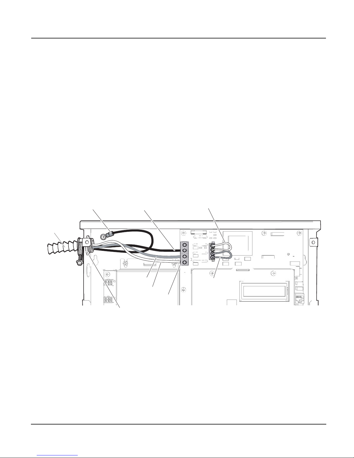
For a single-phase panel (see Figure 7), connect:
• meter terminal A to the voltage disconnect phase A (red wire)
• meter terminal B to the voltage disconnect phase B (black wire)
• meter neutral terminal to neutral bar in the voltage disconnect panel
(white wire)
• earth wire to earth post using lug provided
• meter terminal C is not connected
Figure 7: PowerHawk meter in a 120/240V single-phase connection
© 2011 Triacta Power Technologies All Rights Reserved
13
Page 20
PowerHawk 6212, 6312 and 6412 meters 930-108-01-A.04
Installation 01/2011
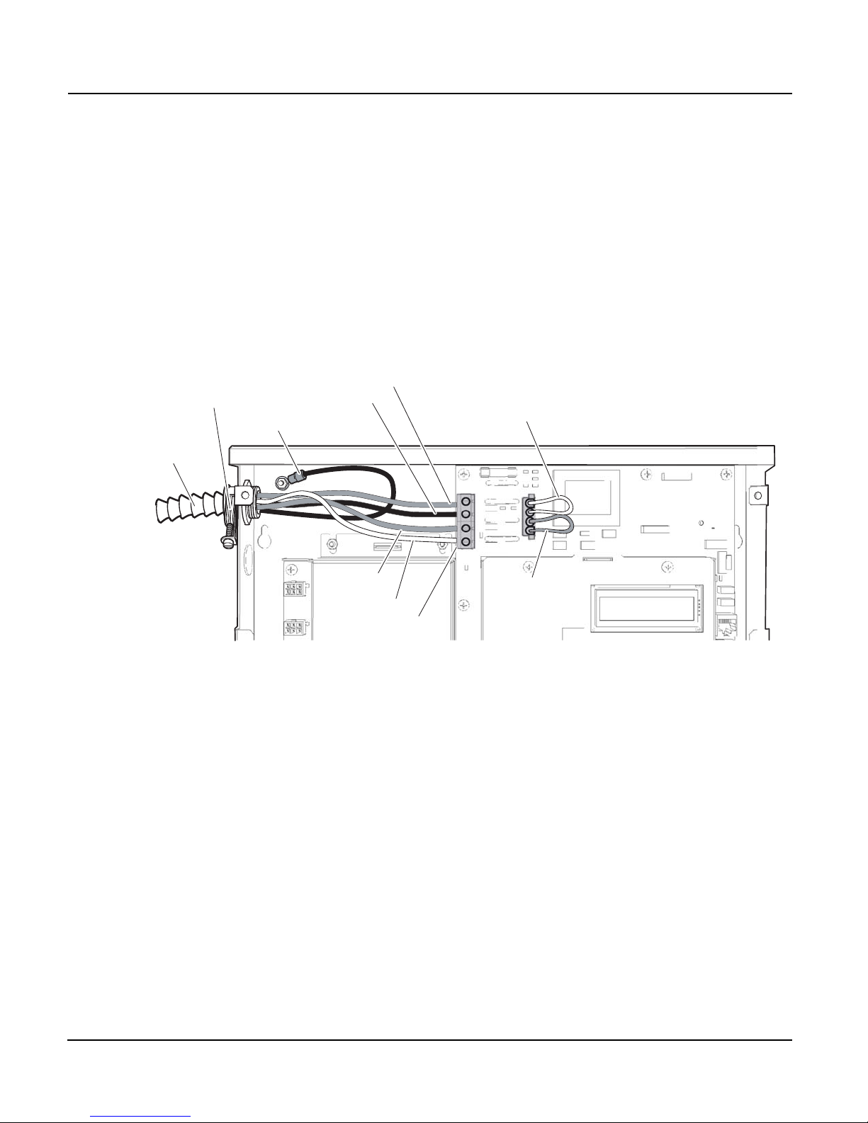
For a three-phase wye panel (see Figure 8), connect:
• Meter terminal A to the voltage disconnect phase A (red wire)
• Meter terminal B to the voltage disconnect phase B (black wire)
• Meter terminal C to the voltage disconnect phase C (blue wire)
• Meter neutral terminal to neutral bar in the voltage disconnect panel
(white wire)
• Earth wire to earth post using lug provided
Figure 8: PowerHawk meter 120/208V three-phase wye service
connection
Phase C (blue)
0.75-inch (1.9-cm) Strain Relief
Earth
BX cable
Phase B (black)
AUXN to N
shorting jumper
Phase A (red)
Neutral (white)
Terminal Block (J3)
AUXA to A
shorting jumper
© 2011 Triacta Power Technologies All Rights Reserved14
Page 21
930-108-01-A.04 PowerHawk 6212, 6312 and 6412 meters
LOAD
SOURCE
ENERGY FLOW
T
H
I
S
SI
D
E
T
OWA
R
DS S
O
U
R
C
E
X1
X2
01/2011 Installation
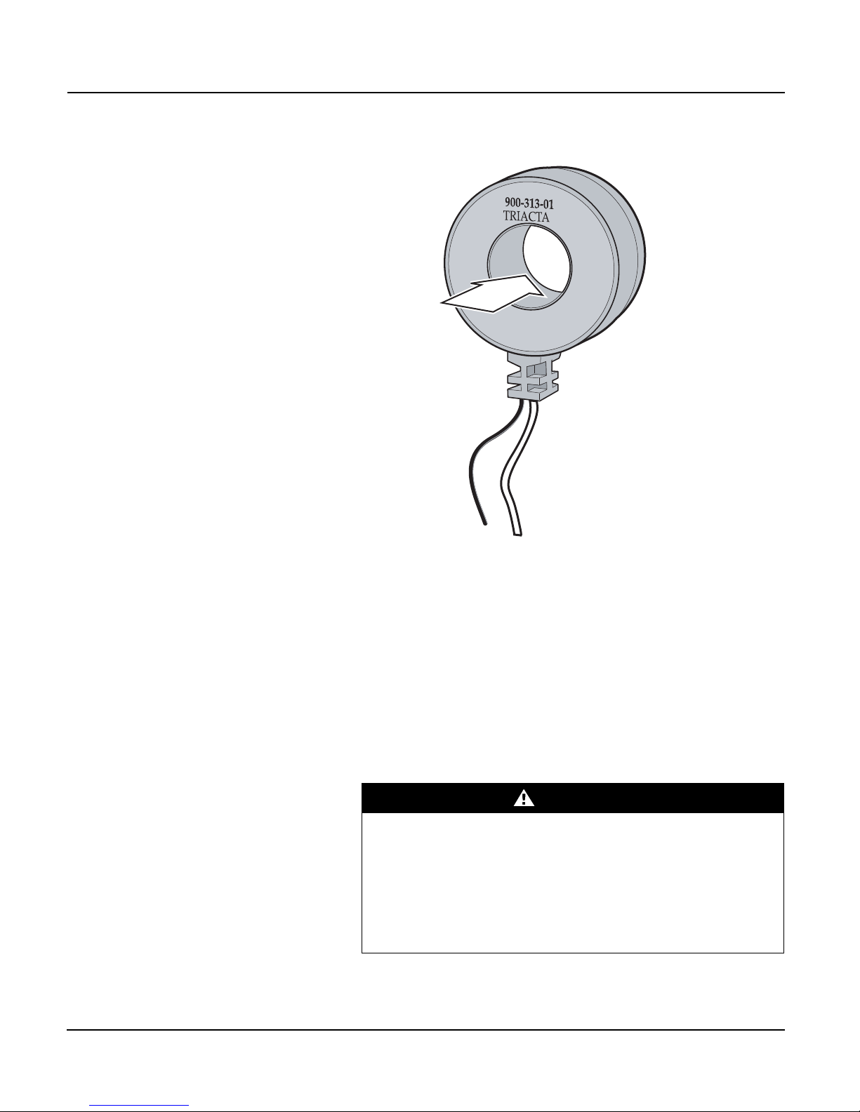
Installing the Current Transformers The three models of PowerHawk meter use current transformers (CTs) with
different secondary outputs. The PowerHawk 6212 meter uses split-core
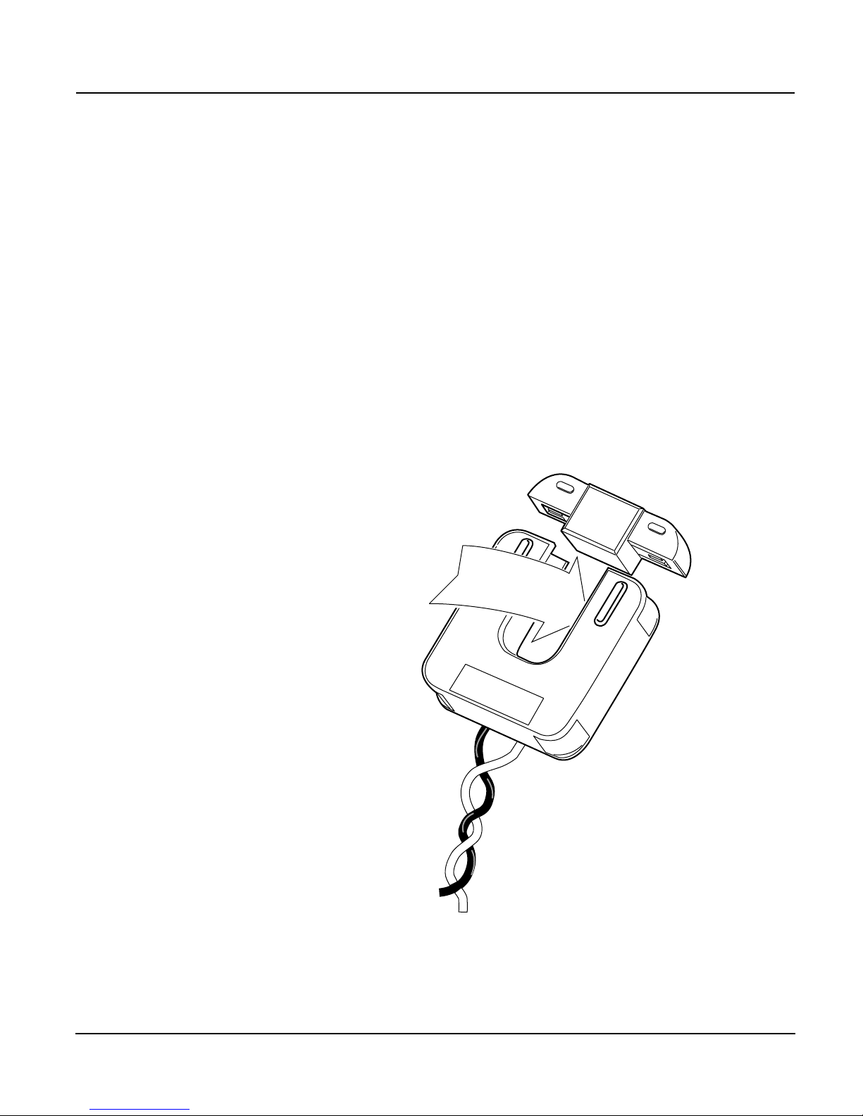
0.333V CTs (see Figure 9), and the PowerHawk 6312 meter uses 80mA CTs
only (see Figure 10) and is typically used where accuracy is important and
long secondary CT wiring is required (up to 300 feet [91.44 meters]).
For instructions, see “Installing the CTs on the PowerHawk 6212 and
PowerHawk 6312” on page 16.
The PowerHawk 6412 uses 5A secondary CTs. For instructions, see
“Installing the 5A CTs on the PowerHawk 6412” on page 19.
Current transformers connect to the PowerHawk 6212 and PowerHawk 6312
meters through the 50-conductor CT cable provided with the meter. Table 2
describes the CT wire pairs and the cable color scheme for each meter point.
You can also find this information on the inside of the meter’s outer cover.
Each CT has an X1 (positive) and X2 (neutral) wire pair and uses butt-splice
connectors to attach the CT to a specific meter wire pair. The direction of the
energy flow is indicated on the CT.
Figure 9: PowerHawk 6212 split-core mV current transformer
© 2011 Triacta Power Technologies All Rights Reserved
15
Page 22
PowerHawk 6212, 6312 and 6412 meters 930-108-01-A.04
Energy
Flow
Load
Source
X1
X2
H1
DANGER
Installation 01/2011
Figure 10: PowerHawk 6312 mA current transformer
Installing the CTs on the PowerHawk 6212 and PowerHawk 6312
Do not apply power until you have made these connections and followed all
of the instructions below:
• connect all CTs to the appropriate circuits
• connect the CTs to the cables
• connect the cables to the PowerHawk meter
To install the mA current transformers on the PowerHawk 6312 or the 0.333V
current transformers on the PowerHawk 6212, follow these steps:
HAZARD OF ELECTRIC SHOCK, EXPLOSION, OR ARC FLASH
• Turn off all power supplying this equipment before working on or
inside the equipment.
• Always use a properly rated voltage sensing device to confirm the
power is off.
• Do not crimp the insulation when making the wire connections.
Failure to follow these instructions will result in death or
serious injury.
© 2011 Triacta Power Technologies All Rights Reserved16
Page 23

930-108-01-A.04 PowerHawk 6212, 6312 and 6412 meters
01/2011 Installation
1. Connect the 50-pin connector to the PowerHawk connector located at
the bottom side of the unit, and secure it in place with the retaining clips.
2. Feed the free end of the cable through the bottom left of the meter
enclosure.
This cable is made up of twisted-pair wires for connecting the individual
CTs to the metered points. The color codes for the X1 (positive) and X2
(neutral) connections for each CT are listed in Table 2 on page 18.
NOTE: The direction of the energy flow is indicated on the CT.
3. Turn off the power feed to the panel where the CTs are being installed.
Always use a properly rated voltage sensing device to confirm power is
off.
4. Feed the CT cable into the panel through an appropriate punch-out with
an approved strain relief.
5. Strip the plastic sheaths back on the cable to an appropriate length to
expose the wire pairs. Cut and strip the CT leads and wire pair leads to
an appropriate length. Crimp the CT leads to the wire pairs for each
meter point.
6. When using solid-core CTs, remove the feed wire from the circuit
breaker, place the CT over the wire, and reconnect to the circuit
breaker. Ensure that the arrow on the CT label is pointing in the
direction of the energy flow (toward the load).
7. When using split-core CTs, separate the halves of the CT and place the
CT over the wire to the circuit breaker. Ensure that the CT is facing the
source as shown on the label. Install cable ties to ensure that the CT
halves are held together securely.
8. Repeat steps 5 to 7 for the remaining CTs.
© 2011 Triacta Power Technologies All Rights Reserved
17
Page 24

PowerHawk 6212, 6312 and 6412 meters 930-108-01-A.04
Installation 01/2011
Table 2: PowerHawk 6212 and PowerHawk 6312 CT color pair
identification
3-phase, 8 meter points Network- or 1-phase, 12 meter points 1-phase, 24 meter points
Meter
point ID
MP1-1 Black Green MP1-1 Black Green MP1-1 Black Green
MP1-2 Black White MP1-2 Black White MP2-1 Black White
MP1-3 Black Red MP2-1 Black Red MP3-1 Black Red
MP2-1 Red Green MP2-2 Red Green MP4-1 Red Green
MP2-2 Red White MP3-1 Red White MP5-1 Red White
MP2-3 Black Orange MP3-2 Black Orange MP6-1 Black Orange
MP3-1 Black Brown MP4-1 Black Brown MP7-1 Black Brown
MP3-2 Black Yellow MP4-2 Black Yellow MP8-1 Black Yellow
MP3-3 Black Blue MP5-1 Black Blue MP9-1 Black Blue
MP4-1 Green Yellow MP5-2 Green Yellow MP10-1 Green Yellow
MP4-2 Green Blue MP6-1 Green Blue MP11-1 Green Blue
MP4-3 Green White MP6-2 Green White MP12-1 Green White
MP5-1 Blue White MP7-1 Blue White MP13-1 Blue White
MP5-2 Green Orange MP7-2 Green Orange MP14-1 Green Orange
MP5-3 Green Brown MP8-1 Green Brown MP15-1 Green Brown
MP6-1 Blue Yellow MP8-2 Blue Yellow MP16-1 Blue Yellow
Connect X1
CT lead to:
Connect X2
CT lead to:
Meter
point ID
Connect X1
CT lead to:
Connect X2
CT lead to:
Meter
point ID
Connect X1
CT lead to:
Connect X2
CT lead to:
MP6-2 Brown White MP9-1 Brown White MP17-1 Brown White
MP6-3 Orange White MP9-2 Orange White MP18-1 Orange White
MP7-1 Red Orange MP10-1 Red Orange MP19-1 Red Orange
MP7-2 Red Yellow MP10-2 Red Yellow MP20-1 Red Yellow
MP7-3 Red Brown MP11-1 Red Brown MP21-1 Red Brown
MP8-1 Blue Orange MP11-2 Blue Orange MP22-1 Blue Orange
MP8-2 Yellow White MP12-1 Yellow White MP23-1 Yellow White
MP8-3 Blue Brown MP12-2 Blue Brown MP24-1 Blue Brown
© 2011 Triacta Power Technologies All Rights Reserved18
Page 25
930-108-01-A.04 PowerHawk 6212, 6312 and 6412 meters
DANGER
01/2011 Installation
Installing the 5A CTs on the PowerHawk 6412
Use the two 12-pair wiring harnesses provided with the meter to connect the
5A CTs to the PowerHawk 6412.
For wire color coding, see Table 3 or the label inside the outer cover of the
meter. Follow these instructions to install the 5A CTs on the PowerHawk
6412.
Do not apply power until you have made these connections and followed all
instructions below:
• connect all CTs to shorting blocks to the appropriate circuits
• connect the shorting blocks to the cables
• connect the cables to the PowerHawk 6412
HAZARD OF ELECTRIC SHOCK, EXPLOSION, OR ARC FLASH
• Turn off all power supplying this equipment before working on or
inside the equipment.
• Always use a properly rated voltage sensing device to confirm the
power is off.
• NEVER open circuit a CT; use the shorting block to short circuit the
leads of the CT before removing the connection from the meter.
• Do not crimp the insulation when making the wire connections.
Failure to follow these instructions will result in death or
serious injury.
1. Connect the two wiring harnesses to the PowerHawk 6412.
The connectors are labeled Plug 1/Plug 5 to Plug 4/Plug 8 on the cable.
This is also labeled on the meter. Ensure the connectors are inserted
in the proper order and that the connectors are securely locked in place.
TM
a. Connect the first wiring harness to the Mate-n-Lok
connectors
1 to 4, and secure the cables to the PowerHawk 6412 chassis
with cable ties.
TM
b. Connect the second wiring harness to the Mate-n-Lok
connectors 5 to 8, and secure the cables to the PowerHawk 6412
chassis with cable ties.
2. Turn off the power feed to the panel where the CTs are being installed.
3. Route the free end of the cable out of the meter enclosure through the
slot in the base of the chassis.
4. Strip the plastic sheaths back to an appropriate length to expose the
wire pairs. Cut and strip the wire pair leads to an appropriate length.
5. Connect the wire pair leads from the meter to the CT shorting block.
See Table 3 for the color pair assignment of each meter point. Ensure
that the CT shorting block is in the shorted position.
6. Connect the CT wire pair leads to the input of the CT shorting block.
See Table 3 for the color pair assignment of each meter point.
7. Remove the feed wire from the circuit breaker, place the CT over the
wire, and reconnect to the circuit breaker. Ensure that the arrow on the
CT label is pointing in the direction of the energy flow (toward the load).
© 2011 Triacta Power Technologies All Rights Reserved
NOTE: The direction of the energy flow is indicated on the CT.
8. Repeat steps 5 to 7 for remaining CTs.
19
Page 26
PowerHawk 6212, 6312 and 6412 meters 930-108-01-A.04
P8
P7
P5
P3
P2
P1
1
2
3
3
1
Legend:
1 Cable tie-down point
2 10/100 BaseTX Ethernet port
3 Pulse in terminal block
P1 Meter point 1 connector plug
P2 Meter point 2 connector plug
P3 Meter point 3 connector plug
P4 Meter point 4 connector plug
P5 Meter point 5 connector plug
P6 Meter point 6 connector plug
P7 Meter point 7 connector plug
P8 Meter point 8 connector plug
_
Installation 01/2011
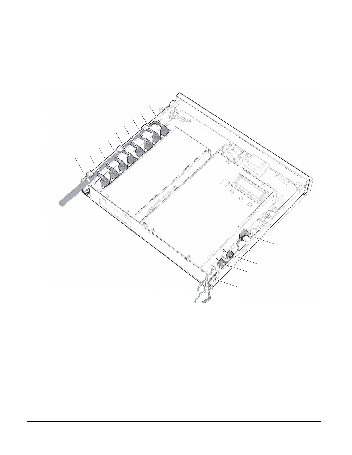
Figure 11 shows the 5A CT wiring harness connected to the PowerHawk
6412.
Figure 11: Connecting the 5A CT wiring harness
© 2011 Triacta Power Technologies All Rights Reserved20
Page 27

930-108-01-A.04 PowerHawk 6212, 6312 and 6412 meters
01/2011 Installation
Table 3: PowerHawk 6412 CT color pair identification
3-phase, 8 meter points Network- or 1-phase, 12 meter points 1-phase, 12 or 24 meter points
Meter
point ID
Cable 1 Cable 1 Cable 1
MP1-1 Black Red MP1-1 Black Red MP1-1 Black Red
MP1-2 Black White MP1-2 Black White MP2-1 Black White
MP1-3 Black Green MP2-1 Black Green MP3-1 Black Green
MP2-1 Black Blue MP2-2 Black Blue MP4-1 Black Blue
MP2-2 Black Yellow MP3-1 Black Yellow MP5-1 Black Yellow
MP2-3 Black Brown MP3-2 Black Brown MP6-1 Black Brown
MP3-1 Black Orange MP4-1 Black Orange MP7-1 Black Orange
MP3-2 Red White MP4-2 Red White MP8-1 Red White
MP3-3 Red Green MP5-1 Red Green MP9-1 Red Green
MP4-1 Red Blue MP5-2 Red Blue MP10-1 Red Blue
MP4-2 Red Yellow MP6-1 Red Yellow MP11-1 Red Yellow
MP4-3 Red Brown MP6-2 Red Brown MP12-1 Red Brown
Cable 2 Cable 2 Cable 2
MP5-1 Black Red MP7-1 Black Red MP13-1 Black Red
MP5-2 Black White MP7-2 Black White MP14-1 Black White
Connect X1
CT lead to:
Connect X2
CT lead to:
Meter
point ID
Connect X1
CT lead to:
Connect X2
CT lead to:
Meter
point ID
Connect X1
CT lead to:
Connect X2
CT lead to:
MP5-3 Black Green MP8-1 Black Green MP15-1 Black Green
MP6-1 Black Blue MP8-2 Black Blue MP16-1 Black Blue
MP6-2 Black Yellow MP9-1 Black Yellow MP17-1 Black Yellow
MP6-3 Black Brown MP9-2 Black Brown MP18-1 Black Brown
MP7-1 Black Orange MP10-1 Black Orange MP19-1 Black Orange
MP7-2 Red White MP10-2 Red White MP20-1 Red White
MP7-3 Red Green MP11-1 Red Green MP21-1 Red Green
MP8-1 Red Blue MP11-2 Red Blue MP22-1 Red Blue
MP8-2 Red Yellow MP12-1 Red Yellow MP23-1 Red Yellow
MP8-3 Red Brown MP12-2 Red Brown MP24-1 Red Brown
MP1-1 Black Red MP1-1 Black Red MP1-1 Black Red
© 2011 Triacta Power Technologies All Rights Reserved
21
Page 28

PowerHawk 6212, 6312 and 6412 meters 930-108-01-A.04
Installation 01/2011
Connecting the Communications Connections for communications using the modem or Ethernet are described
in this section.
Connecting the Phone Line
If the modem reporting option is being used, an analog telephone patch cable
and a splitter may be required to connect the customer phone line to the
PowerHawk meter.
1. Connect the patch cable between the termination block of the phone
line and the PowerHawk meter.
2. Route the cable through the slot in the PowerHawk meter enclosure.
3. See the PowerHawk meter Configuration Guide for instructions on how
to program the meter for dial-out operation before performing a manual
configuration test.
Connecting the Ethernet Cable
If the Ethernet port is used to report data, an RJ45 patch cable is required to
connect the Ethernet port to the local Ethernet network.
1. Route the cable through the slot in the PowerHawk meter enclosure.
2. If the local network automatically assigns IP addresses through a
DHCP server, the PowerHawk meter will be able to report using its
factory default IP settings. If the local network is configured for static IP
addresses, refer to the PowerHawk meter Configuration Guide for
instructions on how to configure default static IP addresses.
Start-Up Sequence Use the following procedure to start up the PowerHawk meter.
1. Ensure that all CT and reference voltage wiring is securely installed.
2. Remove all tools from the work area.
3. Re-install all cover plates and equipment covers.
4. Power up the meter. The LCD on the front panel of the meter indicates
the operating status of the unit as follows:
a. Initial power up message “PowerHawk 6X12”
b. After the internal configuration is complete, the display shows
default information for the first meter.
Manually Testing Communications
This procedure clears the meter memory, manually tests the
communications from the PowerHawk meter, and updates the meter clock.
To force the meter to send data, follow these steps:
1. Press and hold the Display button for 5 to 7 seconds until the
diagnostics mode is displayed, then release.
2. If communicating via Ethernet, press the Display button until "Local IP
Address" appears on the display.
a. If the IP address is 169.254.0.10, the meter has not found a
DHCP server. As a result, the meter will use its default IP
configuration and may not be able to report. See the PowerHawk
meter Configuration Guide for instructions on how to program
default IP addresses.
b. If the IP address is not 169.254.0.10, the meter has acquired an
IP address from the local network, and will be able to report data
and synchronize time.
© 2011 Triacta Power Technologies All Rights Reserved22
Page 29

930-108-01-A.04 PowerHawk 6212, 6312 and 6412 meters
01/2011 Installation
3. Press the Display button until the “Send” command appears on the
display.
4. Press the center or the right arrow button to manually force the
PowerHawk meter to report metering data using the Ethernet or
modem connection. This clears data from the PowerHawk meter
memory, and ensures the time is set correctly.
Pulse Inputs There are two pulse in terminal blocks in the PowerHawk meter, as shown in
Figure 11. Each terminal block has a negative terminal pin on the right and a
positive terminal pin on the left. The pulse inputs are compatible with both dry
form A contacts, and solid-state form A contacts. The inputs are not
polarity-sensitive to dry relay contacts. When the pulsing device provides
solid-state form A outputs, the negative terminal from the source device must
be connected to the negative terminal of the PowerHawk meter pulse in
terminal block.
Display Navigation The PowerHawk meter has three buttons to control the information
presented on the LCD. The display has a normal and a diagnostics mode.
The PowerHawk meter starts in normal mode, and enters diagnostics mode
when the Display button is pressed and held for 5 seconds. To adjust the
contrast, hold down the Display button, and use the right and left arrow
buttons to increase and decrease the contrast respectively.
Normal Mode
In Normal mode, the Display button scrolls through the information for each
meter. The left and right arrow buttons select the previous or next meter
points respectively. The following information is available:
• Real Energy Delivered kWh D
• Real Energy Received kWh R
• Real Power Watts
• Reactive Energy Delivered KVarhD
• Reactive Energy Received KVarhR
• Reactive Power Var
In Normal mode, the right and left arrow buttons scroll the display from meter
points 1 to 8, 1 to 12, or 1 to 24, depending on your configuration.
Diagnostics Mode
Diagnostics mode is accessed by pressing and holding the Display button for
5 seconds. In Diagnostics mode, pressing the Display button will scroll
through the following additional information:
• Send data command
• CT Primary value and Real Power Watts per phase
• Voltage per phase
• Local IP address
• Reset factory default IP address command
• Date and time (UTC)
© 2011 Triacta Power Technologies All Rights Reserved
23
Page 30

PowerHawk 6212, 6312 and 6412 meters 930-108-01-A.04
Installation 01/2011
In Diagnostics mode, the right and left arrow buttons scroll the display from
meter 1 through N. When the local IP address is shown on the LCD, use the
right and left arrow buttons to scroll through the following information:
• Remote host server IP address
• Time server IP address
• Default IP address
• Default NetMask
• Default gateway
• PPP user name
• Phone number
• AT command string
• Alternate phone number
• Unit serial number
• Firmware build number
• Ethernet port MAC address
• Firmware revision
• Voltage transformer ratio
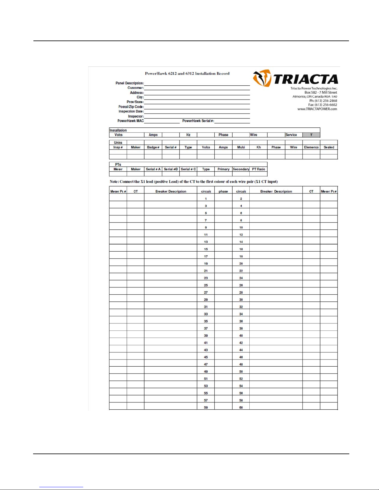
Recording the Meter Map The final step in the installation process is to complete the Installation
Record, and record the mapping of the meters to the wired points. A copy of
Figure 12, which is organised to resemble a breaker panel, is provided with
each PowerHawk meter, and is to be completed and delivered to your
system administrator.
© 2011 Triacta Power Technologies All Rights Reserved24
Page 31
930-108-01-A.04 PowerHawk 6212, 6312 and 6412 meters
01/2011 Installation
Figure 12: Installation Record (sample shown)
© 2011 Triacta Power Technologies All Rights Reserved
25
Page 32
PowerHawk 6212, 6312 and 6412 meters 930-108-01-A.04
DANGER
Fuse holder
Fuse
Fuse cover
Maintenance 01/2011
MAINTENANCE Do not perform any operation or maintenance procedures that are not
described in this product documentation. No preventive maintenance is
required on any of the equipment. Visually inspect the equipment yearly and
ensure it is free of dust or other particles. If necessary, wipe with a clean
cloth. Individual components are not user-serviceable and must be returned
to Triacta Power for repair.
Fuse Replacement
HAZARD OF ELECTRIC SHOCK, EXPLOSION, OR ARC FLASH
• Apply appropriate personal protective equipment (PPE) and follow
safe electrical work practices. See NFPA 70E.
• Turn off all power supplying this equipment before working on or
inside equipment.
• Always use a properly rated voltage sensing device to confirm
power is off.
• Replace all devices, doors and covers before turning on power to
this equipment.
Failure to follow these instructions will result in death or serious
injury.
1. Turn off all sources of power before attempting to replace the fuse.
2. Remove the outer cover from the unit.
3. Locate fuse F1 at the top left corner inside the unit.
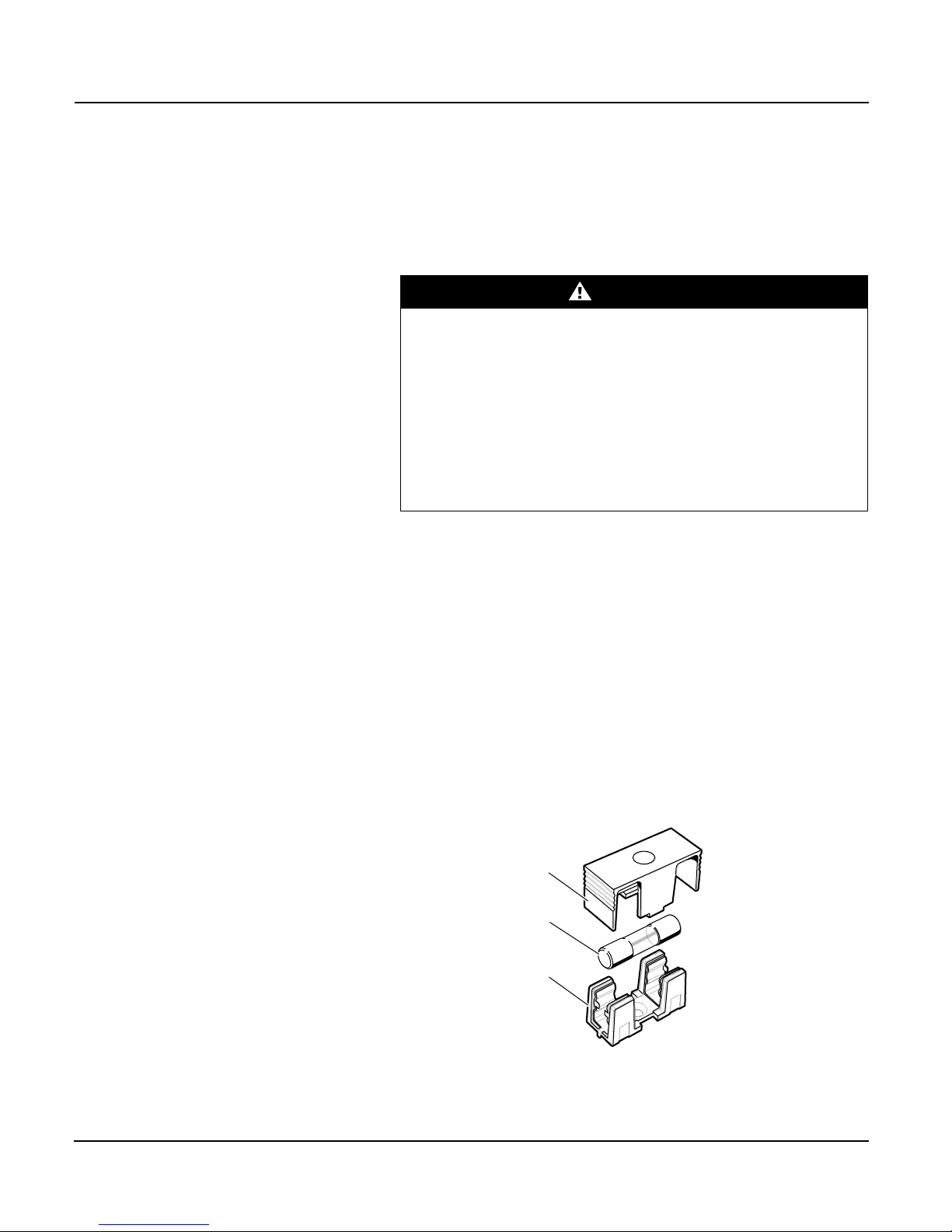
4. Remove the fuse cover, then remove the fuse from the holder as shown
in Figure 13.
5. Replace fuse F1 with a fuse that meets the specifications listed in
Table 1 on page 2.
6. Replace the fuse cover.
7. Re-install the cover and turn on the power source.
Figure 13: Replacing the fuse
© 2011 Triacta Power Technologies All Rights Reserved26
Page 33
930-108-01-A.04 PowerHawk 6212, 6312 and 6412 meters
CAUTION
01/2011 Regulatory Compliance
REGULATORY COMPLIANCE The PowerHawk meter must be installed by a certified electrician with
knowledge of local safety regulations. Initial installation of the unit, and any
subsequent modification to the unit, must be inspected by the local electrical
safety authority.
The PowerHawk meter complies with the standards listed in Table 4.
Table 4: Regulatory Compliance
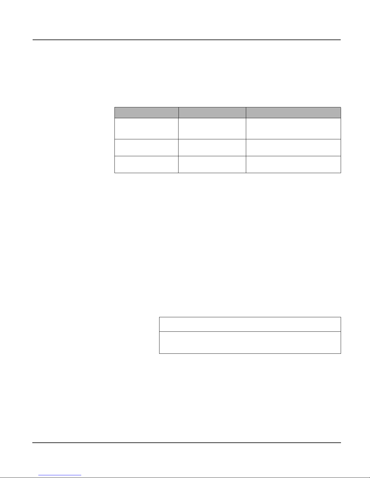
Discipline Applicable country/region Regulatory and industry standard
Safety United States
Canada
Emissions (EMC) United States
Canada
Surge power/telephone lines United States
Canada
TUV and UL certified to IEC/EA/UL/CSA
61010-1 2
CSA-C22.2 No. 61010-1-04
FCC Part 15 Class A, ICES-003 EN55022, IEC
6100-4-5
ANSI/TIA968-A: 2002
nd
Edition
Equipment servicing and access The information in this section must be considered as a mandatory
requirement, and must be strictly adhered to when installing and operating
PowerHawk 6212, 6312 and 6412 meters.
Access to equipment
The equipment must be accessible to authorized personnel only. Equipment
must be installed in areas where access can be restricted.
Servicing the equipment
No preventive maintenance is required on any of the equipment. Visually
inspect the equipment yearly and ensure it is free of dust or other particles.
If necessary, wipe with a clean cloth.
Component servicing
Individual components are not user-serviceable, and must be returned to
Triacta Power for repair. If an equipment fault occurs, do not attempt to repair
the faulty component.
© 2011 Triacta Power Technologies All Rights Reserved
All maintenance activities should be performed by qualified personnel
only. Do not perform any operating or maintenance procedures that are
not described in the product documentation provided by Triacta Power.
27
Page 34
PowerHawk 6212, 6312 and 6412 meters 930-108-01-A.04
Regulatory Compliance 01/2011
Graphical symbols
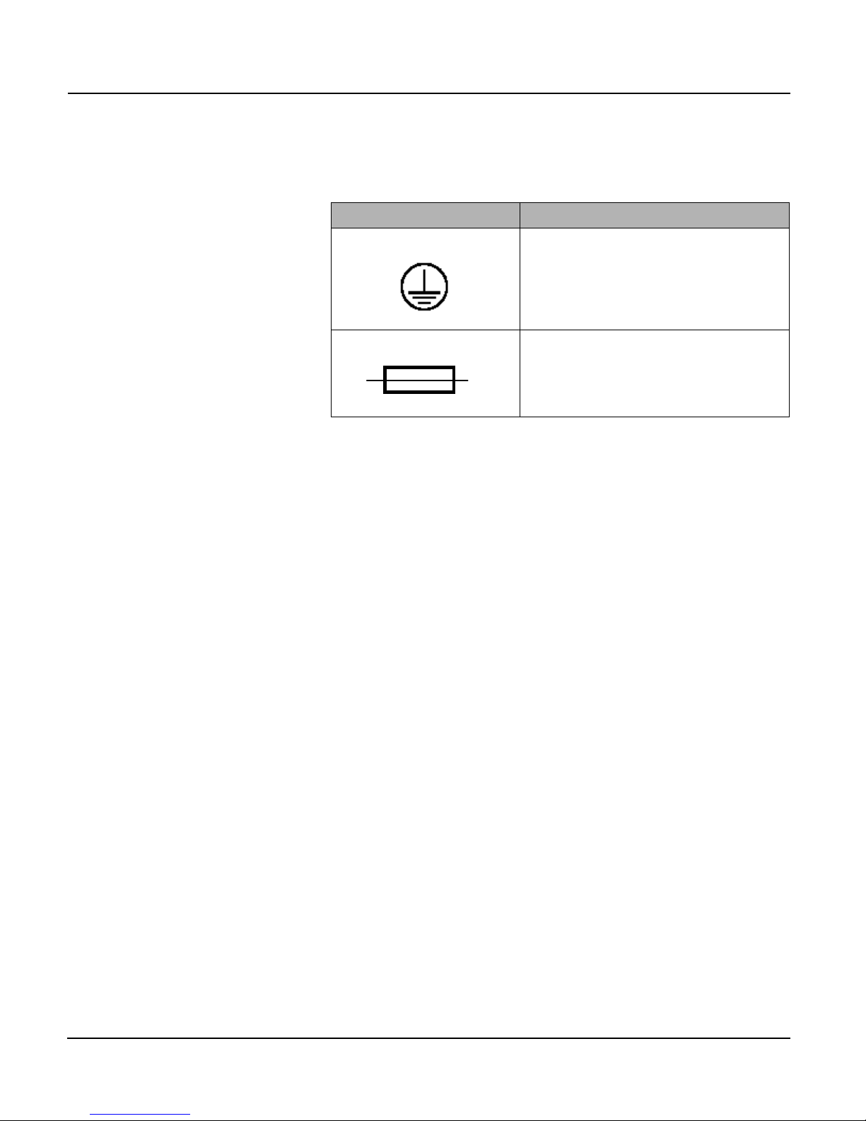
Table 5 shows the graphical symbols that appear on the equipment.
Table 5: Graphical symbols that appear on equipment
Symbol Description
Indicates the supply wire protective earth, also known as
chassis ground, for the primary ground.
This symbol indicates a replaceable fuse.
© 2011 Triacta Power Technologies All Rights Reserved28
Page 35

930-108-01-A.04 PowerHawk 6212, 6312 and 6412 meters
01/2011 Index
Index
Numerics
120V
install reference voltage and power cable
480V installation
typical configuration 11
5A current transformers
install 19
A
audience 1
C
compliance
electrical safety
current transformers 2
install 16
6
D
dimensions 2
E
electrical safety compliance 6
equipment
access 27
servicing 27
equipment servicing 27
F
fuse rating 2
I
install
5A current transformers 19
current transformers 16
voltage transformers 10
installation 7
installation procedures
overview
8
M
maximum altitude 2
maximum pulse per second 2
measurement accuracy 2
meter
CT color pair identification
CT colour pair identification 21
current transformers 2
dimensions 2
fuse rating 2
installation in a single-phase panel 13
installation in a three-phase wye panel 14
internal view 4–5
maximum altitude 2
maximum pulse per second 2
measurement accuracy 2
minimum pulse width 2
mounting 9
NVM storage 2
18
12
onboard Ethernet port 2
onboard modem 2
operating humidity 2
operating temperature 2
pollution degree 2
pulse inputs 1 and 2 2
reference input voltage 2
reference voltage tolerance 2
serial port 2
specifications 2
supply voltage and current 2
usage environment 2
weight 2
meter map
recording
minimum pulse width 2
mounting 9
24
N
NVM storage 2
O
onboard Ethernet port 2
onboard modem 2
operating humidity 2
operating temperature 2
P
pollution degree 2
pre-installation 7
pulse inputs 23
pulse inputs 1 and 2 2
R
reference input voltage 2
reference voltage and power cable installation
120V application 12
reference voltage tolerance 2
S
serial port 2
servicing equipment 27
site planning 8
site preparation
lighting
power 8
specifications 2
start-up sequence 22
supply voltage and current 2
8
U
usage environment 2
V
voltage transformers
10
install
English
© 2011 Triacta Power Technologies All Rights Reserved
29
Page 36

PowerHawk 6212, 6312 and 6412 meters 930-108-01-A.04
Index 01/2011
W
English
weight 2
© 2011 Triacta Power Technologies All Rights Reserved30
Page 37

930-108-01-A.04 PowerHawk 6212, 6312 and 6412 meters
01/2011 user notes
USER NOTES
© 2011 Triacta Power Technologies All Rights Reserved
31
Page 38

PowerHawk 6212, 6312 and 6412 meters 930-108-01-A.04
user notes 01/2011
© 2011 Triacta Power Technologies All Rights Reserved32
Page 39

930-108-01-A.04 PowerHawk 6212, 6312 and 6412 meters
01/2011
© 2011 Triacta Power Technologies All Rights Reserved
Page 40

PowerHawk 6312 and 6412 meters
Installation Guide
Triacta Power Technologies Inc.
7 Mill Street
Almonte, Ontario
K0A 1X0
www.triacta.com
Electrical equipment should be installed, operated, serviced, and maintained only by qualified
personnel. No responsibility is assumed by Triacta Power for any conseq uences arising out of the
use of this material.
930-108-01-A.04 © 2011 Triacta Power Technologies All Rights Reserved
01/2011
 Loading...