

Page 1

Installation Guide
930-148-01-A.00
11/2018
Page 2
Triacta GATEWAY
© 2018 Triacta Power Solutions LP All Rights Reserved
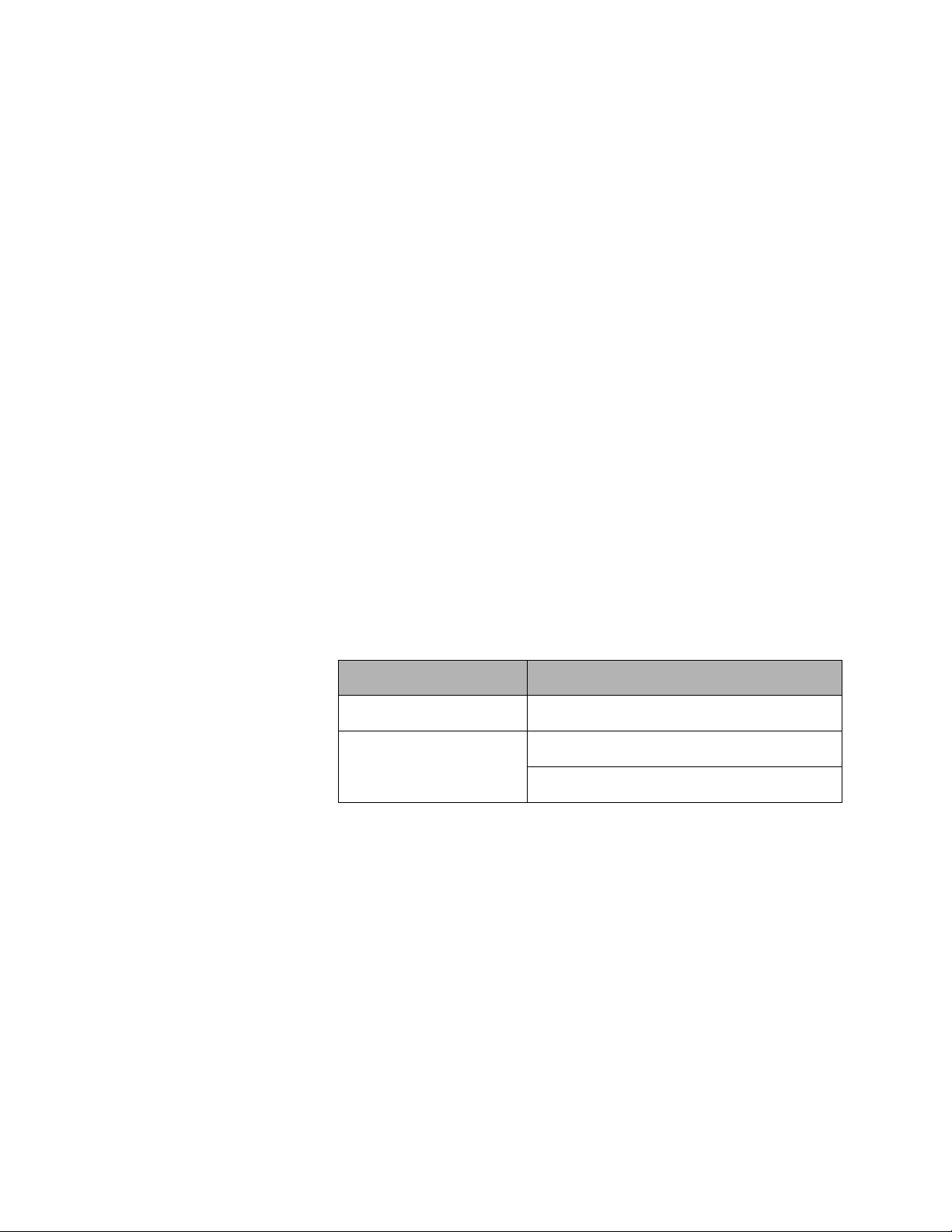
DANGER
DANGER indicates an imminently hazardous situation which, if not avoided, will
result in death or serious injury.
WARNING
WARNING indicates a potentially hazardous situation which, if not avoided, can
result in death or serious injury
CAUTION
CAUTION indicates a potentially hazardous situation which, if not avoided, can
result in minor or moderate injury.
NOTICE
NOTICE is used to address practices not related to physical injury. The safety
alert symbol shall not be used with this signal word.
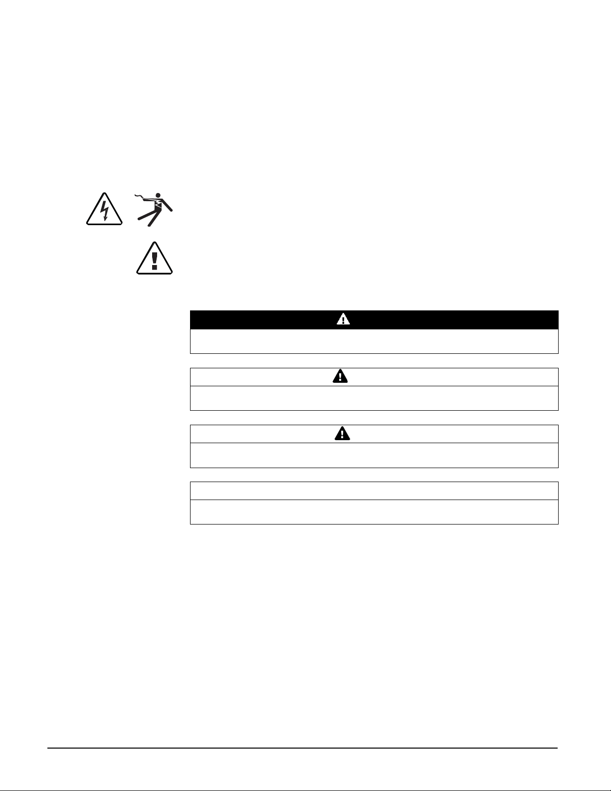
Hazard Categories and Special Symbols
Read these instructions carefully and look at the equipment to become
familiar with the device before trying to install, operate, service or maintain it.
The following special messages may appear throughout this manual or on
the equipment to warn of potential hazards or to call attention to information
that clarifies or simplifies a procedure.
The addition of either symbol to a “Danger” or “Warning” safety label indicates that
an electrical hazard exists which will result in personal injury if the instructions are
not followed.
This is the safety alert symbol. It is used to alert you to potential personal injury
hazards. Obey all safety messages that follow this symbol to avoid possible injury
or death.
Please note
Electrical equipment should be installed, operated, serviced and maintained only by
qualified personnel. No responsibility is assumed by Triacta for any consequences
arising out of the use of this material.
A qualified person is one who has skills and knowledge related to the construction,
installation, and operation of electrical equipment and has received safety training
to recognize and avoid the hazards involved.
Page 3

Triacta GATEWAY
© 2018 Triacta Power Solutions LP All Rights Reserved
Notices
FCC Part 15 Notice
This device complies with part 15 of the FCC Rules. Operation is subject to the following two
conditions: (1) This device may not cause harmful interference, and (2) this device must accept any
interference received, including interference that may cause undesired operation. Caution: Changes or
modifications not expressly approved by the party responsible for compliance could void the user's
authority to operate this equipment
Industry Canada Class B Emission Compliance Statement
This device complies with Industry Canada license-exempt RSS standard(s). Operation is
subject to the following two conditions: (1) this device may not cause interference, and (2) this device
must accept any interference, including interference that may cause undesired operation of the device.”
Le présent appareil est conforme aux CNR d'Industrie Canada applicables aux appareils radio exempts
de licence. L'exploitation est autorisée aux deux conditions suivantes : (1) l'appareil ne doit pas produire
de brouillage, et (2) l'utilisateur de l'appareil doit accepter tout brouillage radioélectrique subi, même si le
brouillage est susceptible d'en compromettre le fonctionnement
This equipment does not exceed the Class B limits for radio noise emissions from digital apparatus as
set out in the radio interference regulations of the Canadian ICES-003.
Avis de conformité aux normes d'Industrie Canada. Cet appareil numérique
de la classe B est conforme à la norme NMB-003 du Canada.
This device contains license-exempt transmitter(s)/receiver(s) that comply with Innovation, Science and
Economic Development Canada’s license-exempt RSS(s). Operation is subject to the following two
conditions:
1. This device may not cause interference
2. This device must accept any interference, including interference that may cause undesired
L’émetteur/récepteur exempt de licence contenu dans le présent appareil est conforme aux CNR
d’Innovation, Sciences et Développement économique Canada applicables aux appareils radio exempts
de licence.
L’exploitation est autorisée aux deux conditions suivantes :
FCC and Industry Canada notices for Wi-Fi 2.4GHz
IC ID: 23814-GATEWAY
FCC ID: SCR-GATEWAY
operation of the device.
1. L’appareil ne doit pas produire de brouillage;
2. L’appareil doit accepter tout brouillage radioélectrique subi, même si le brouillage est
susceptible d’en compromettre le fonctionnement.
Page 4
Triacta GATEWAY
© 2018 Triacta Power Solutions LP All Rights Reserved
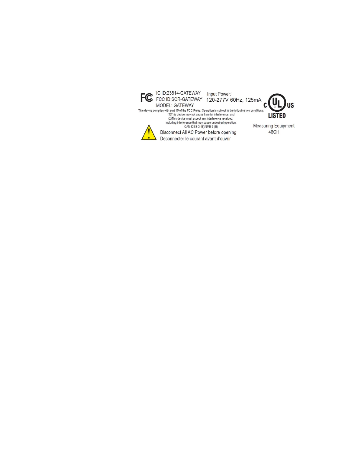
UL (Underwriters Laboratories)
Example:
G1834 = Slot 1 = 100mA Measurement Module
Slot 2 = 80mA Measurement Module
Slot 3 = 333mV Measurement Module
Slot 4 = Pulse Counter Measurement module
Note: Measurement modules can appear in any order and can be
any mix of types, including one type only.
UL (Underwriters Laboratories) are listed by the American Federal Occupational Safety and Health
Administration (OSHA) under NRTL (Nationally Recognized Testing Laboratory) program. They are also
accredited by Standards Council of Canada. This equipment complies with UL 61010-1 Third Edition
and CSA C22.2 No. 61010-1-12.
The regulatory product label covers any combination of measurement modules used on this product.
This can also include the same module type in all slots.
.
Page 5

Triacta GATEWAY
© 2018 Triacta Power Solutions LP All Rights Reserved
5
5
Table of Contents
Introduction ...................................................................................................................................................................... 7
Scope ................................................................................................................................................................................. 7
SAFETY PRECAUTIONS ....................................................................................................................................................... 8
System Specifications ........................................................................................................................................................ 9
Dimensions ...................................................................................................................................................................... 11
System Description ......................................................................................................................................................... 12
Triacta GATEWAY Meter Head .................................................................................................................................... 13
Triacta GATEWAY Meter Base .................................................................................................................................... 13
Triacta GATEWAY Voltage Module ............................................................................................................................. 13
Triacta GATEWAY CT / Pulse Wiring Modules ............................................................................................................ 15
Triacta GATEWAY Flex configuration .......................................................................................................................... 16
Pre-Installation Instructions ............................................................................................................................................ 17
Site Planning ................................................................................................................................................................ 17
Access to Power and Lighting ..................................................................................................................................... 17
Installation Instructions ................................................................................................................................................... 18
Mount the Meter Base Module .................................................................................................................................. 18
Install CT / Pulse Wiring Modules into the Meter Base Unit ...................................................................................... 19
Install disconnect devices for sense and control voltages ........................................................................................... 19
Connect Control and Sense Voltage Wiring ................................................................................................................. 19
Install and Connect CTs ............................................................................................................................................... 24
Connect Pulse Inputs .................................................................................................................................................. 26
Connect the Ethernet Cable ........................................................................................................................................ 27
Install the Cover .......................................................................................................................................................... 27
Record the Meter Map ............................................................................................................................................... 28
MAINTENANCE ................................................................................................................................................................ 30
Fuse Replacement ....................................................................................................................................................... 30
Meter Head Servicing or Replacement ....................................................................................................................... 31
Appendix 1: Current Transformers Overview ................................................................................................................. 32
CT Types ...................................................................................................................................................................... 32
CT Orientation ............................................................................................................................................................. 33
Page 6

Triacta GATEWAY
© 2018 Triacta Power Solutions LP All Rights Reserved
6
6
Wiring polarity ........................................................................................................................................................ 33
CT
CT Phasing ................................................................................................................................................................... 33
CT Shorting and Termination ...................................................................................................................................... 34
CT/Pulse Wiring Modules ............................................................................................................................................ 34
CT Naming designations .............................................................................................................................................. 35
Appendix 2: Triacta GATEWAY Part Number Configuration Guide ................................................................................ 37
Equipment servicing and access ..................................................................................................................................... 38
Page 7

Triacta GATEWAY
© 2018 Triacta Power Solutions LP All Rights Reserved
7
7
Introduction
This document describes the Triacta GATEWAY system, including procedures to install and
start up the unit:
This documentation is intended for those responsible for installing the Triacta GATEWAY.
Installers must be qualified electricians with knowledge of local and national code
requirements. See “Safety Precautions” on page 7.
Scope
This Guide is for the mechanical and electrical installation of the Triacta GATEWAY.
Refer to the Triacta GATEWAY Configuration and Operations Guide for device configuration,
commissioning, and operation of the Triacta GATEWAY.
Page 8

Triacta GATEWAY
© 2018 Triacta Power Solutions LP All Rights Reserved
8
8
DANGER
HAZARD OF ELECTRIC SHOCK, EXPLOSION, OR ARC FLASH.
SAFETY PRECAUTIONS
Carefully observe these safety instructions.
•
Apply appropriate personal protective equipment (PPE) and follow
safe electrical work practices. See NFPA 70E.
• Only qualified electrical workers should install this equipment. Such
work should be performed only after reading this entire set of
instructions.
• The equipment must be accessible to authorized personnel only.
Equipment must be installed in areas where access can be
restricted.
• NEVER work alone.
• Before performing visual inspections, tests, or maintenance of this
equipment, disconnect all sources of electric power. Assume that all
circuits are live until they have been completely de-energized,
tested, and tagged. Pay particular attention to the design of the
power system. Consider all sources of power, including the
possibility of back feeding.
• Turn off all power supplying the meter and the equipment in which
it is installed before working on it.
• Always use a properly rated voltage sensing device to confirm that
all power is off.
• Before closing all covers and doors, carefully inspect the work area
for tools and objects that may have been left inside the equipment.
• Successful equipment operation requires proper handling,
installation, and operation. Neglecting fundamental installation
requirements can lead to personal injury as well as damage to
electrical equipment or other property.
• NEVER bypass external fusing.
• NEVER short the secondary of a Potential Transformer (PT).
• Always short the secondary of a current transformer prior to
disconnecting current input loads.
Failure to follow these instructions will result in death or serious
injury.
Page 9

Triacta GATEWAY
© 2018 Triacta Power Solutions LP All Rights Reserved
9
9
Type
Description
Mechanical
Dimensions
Height: 15.52 in. (39.4 cm) Width: 12 in. (38.9 cm) Depth: 2.125 in. (9.0 cm)
Weight
8.77 lb (3.98 kg) - Fully configured
Voltage Inputs
Sense voltages
Vref1 and Vref2
90V to 300V 50/60Hz
1W+N+Protective Earth
2W+N+Protective Earth Wye
3W+N+Protective Earth Wye
3W+Protective Earth Delta
Aux Power Input
90V to 300V AuxA-AuxN, 15 watts max, 50/60 Hz
Fuse rating (F1)
3.15A, 500V Slow Blow 5 x 20mm
Current Sensing Inputs (All CTs must be UL recognized/listed.)
80 mA CT module
Meter burden: 4.1 ohms
100 mA CT module
Meter burden: 3.28 ohms
333mV CT Module
Meter burden: 20 Kohms
Electrical Metering Accuracy
Measurement accuracy
Measurem ent Canada Approved in accordance with EG07
U.S.A. ANSI C12.20 Class 0.5
IEC 62053-22 Class 5S for EU
(Accuracy compliant when used with 0.3% CTs)
Safety
UL/CSA 61010 Ed3 300V CAT II
• CANADA - CAN/CSA-C22.2 No. 61010-1-12 (IEC 61010-1:2010, MOD)
• USA - UL61010-01 (IEC 61010-1:2010, MOD)
Pulse inputs
Pulse Input Module
Dry Contact form A and solid-state form A compatible
Internal 3.3V pull-up
5Vdc pulse required for Solid State
Maximum frequency 200 Hz
Minimum pulse width 2.0 ms
Memory Storage
Size
15 Gigabytes
Storage Time
10 Years
Meter Head Unit Communications Interfaces
Ethernet
10/100BaseT 802.3-2002; RJ45
Wi-Fi
802.11 b,g,n 2.4 GHz
System Specifications
Table 1 lists the system specifications of the Triacta GATEWAY
Table 1: Triacta GATEWAY specifications
Page 10

Triacta GATEWAY
© 2018 Triacta Power Solutions LP All Rights Reserved
10
10
USB
USB 2.0 (For Future use)
1 x Host, 1 x OTG
Environmental
Operating temperature
-40 to 70oC (No LCD display below -20oC)
Operating humidity
5% to 95% non-condensing
Usage environment
Indoor environment, NEMA 250 Type II
Maximum altitude
9843 ft (3000 m)
Pollution degree
2
Installation category
II
Measurement category
II
Use the unit only in accordance with the electrical power rating.
The unit is only to be installed by a qualified electrician
Initial installation of the unit must be inspected by the local electrical Inspection Authority
Install the unit in compliance with the following local and national electrical codes:
Canada: Canadian Electrical Code, Part I, CSA C22.1
United States: National Fire Protection Association (NFPA) 70; US National
Electrical Code
Elsewhere: International Electro-technical Commission (IEC) 364, Part 1-7
Ensure that the unit is properly earthed
Provide a disconnect device to disconnect the meter from each supply source. Place these
devices in close proximity to the equipment and within easy reach of the operator.
If the equipment is installed or used in a manner other than that specified in this document, it
may void your warranty or impair the protection of the equipment
Page 11

Triacta GATEWAY
© 2018 Triacta Power Solutions LP All Rights Reserved
11
11
Dimensions
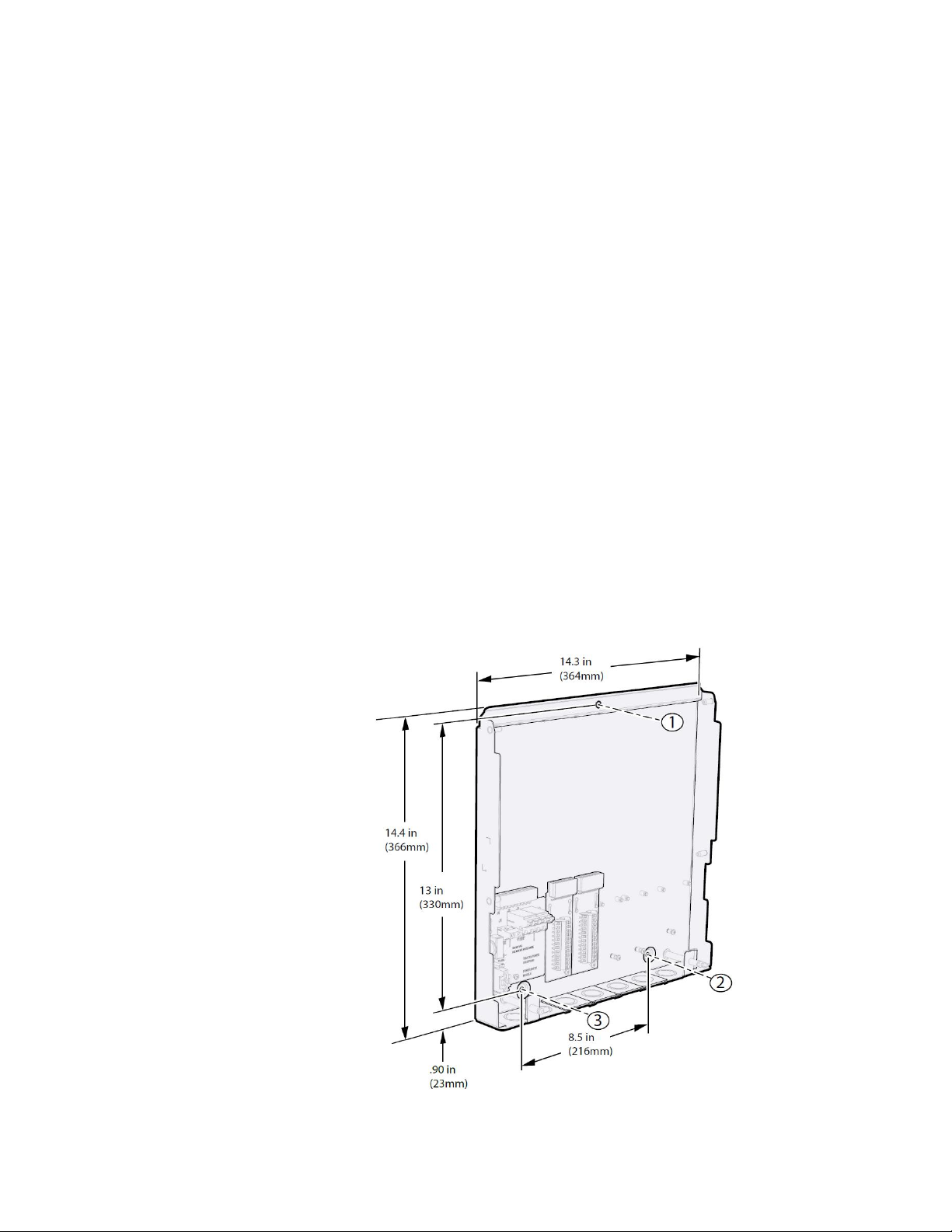
Figure 1: Triacta GATEWAY Dimensions
Page 12
Triacta GATEWAY
© 2018 Triacta Power Solutions LP All Rights Reserved
12
12
System Description
The Triacta GATEWAY is a modular, high density electrical meter and pulse collector system
for Measurement and Verification, Energy Management, and tenant billing applications. It is an
industrial grade, rapidly deployable platform with powerful communications options that will fit
any building use.
The Triacta GATEWAY system architecture consists of separate Triacta GATEWAY Meter
Base and Meter Head units. The Meter Base can be installed, and the electrical connections
terminated by electrical contractors, independently of the TRIACTA GATEWAY Meter Head.
The Triacta GATEWAY Meter Head may be installed at a later time by a technician with no
electrical accreditation.
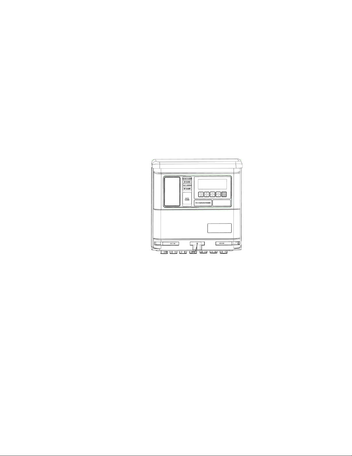
Figure 2: Triacta GATEWAY External View
Page 13

Triacta GATEWAY
© 2018 Triacta Power Solutions LP All Rights Reserved
13
13
Figure 3: Triacta GATEWAY Internal view
Figure 2 shows the internal view of the Triacta GATEWAY .
Triacta GATEWAY Meter Head
The Meter Head unit supports the following:
One to four measurement modules each supporting twelve inputs for 80mA CTs,
100mA CTs, 333mV CTs or pulse counters.
Large front panel 4X20 LCD display for manual meter reading and diagnostics
On-board Wifi for craft interface hotspot
On-board 10/100BaseT Ethernet
Two USB-2.0 ports for future use
Dual processor architecture for enhanced system capability and flexibility
Triacta GATEWAY Meter Base
The Triacta GATEWAY Meter Base supports connection points for the following:
One or two Voltage Reference Inputs
One optional Auxiliary Control Voltage Input
One to four self-shorting input modules supporting up to 12, 24, 36 or 48 wire pairs for
CT’s or pulse output devices.
Optional future communication modules.
Triacta GATEWAY Voltage Module
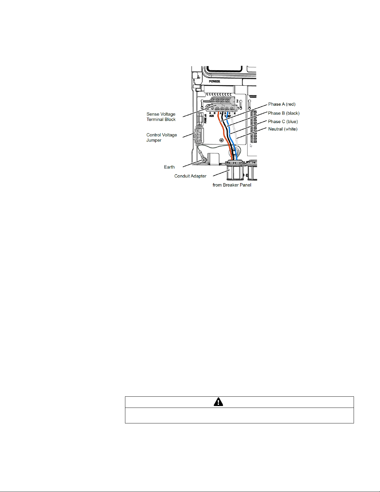
The Voltage Module has two separate Sense Voltage inputs, an Auxiliary Control Voltage
input, and a control voltage jumper.
Page 14
Triacta GATEWAY
© 2018 Triacta Power Solutions LP All Rights Reserved
14
14
WARNING
WARNING The control Voltage Jumper must be removed if there is a separate
voltage source connected to the Auxiliary Control Voltage Input.
Figure 4: Voltage Module
The two sense voltage inputs (Vref1 and Vref2; A, B, C, N) provide the phase voltages
(VAC) used for metering one or two different service types. Ref 1 could be used for
120V/208V 3ph 4wire, and Ref. 2 could be used for a 277V/480V 3 ph 4 wire service. Either
voltage reference can be assigned to any configured meter point, regardless of which CT
module or which CT inputs the meter point uses.
When the control voltage jumper is installed it connects Phase A from the Vref1 sense
voltage input to the Triacta GATEWAY device control voltage circuitry. This eliminates the
requirement for a separate voltage connection to the Auxiliary Control Voltage Input.
Separate control and sense voltage wiring is required when using the Triacta GATEWAY
with a Triacta PT Module, or when the meter is expected to be ON at all times - even when
the sense voltage source is OFF. I.E. the sense voltage is from an emergency power panel
that is not always ON.
Both the control voltage and sense voltage inputs will accept panel voltages from 120VAC to
277VAC. If the reference voltage for the circuit/s to be metered is larger than 277VAC,
external potential transformers (PTs) are required.
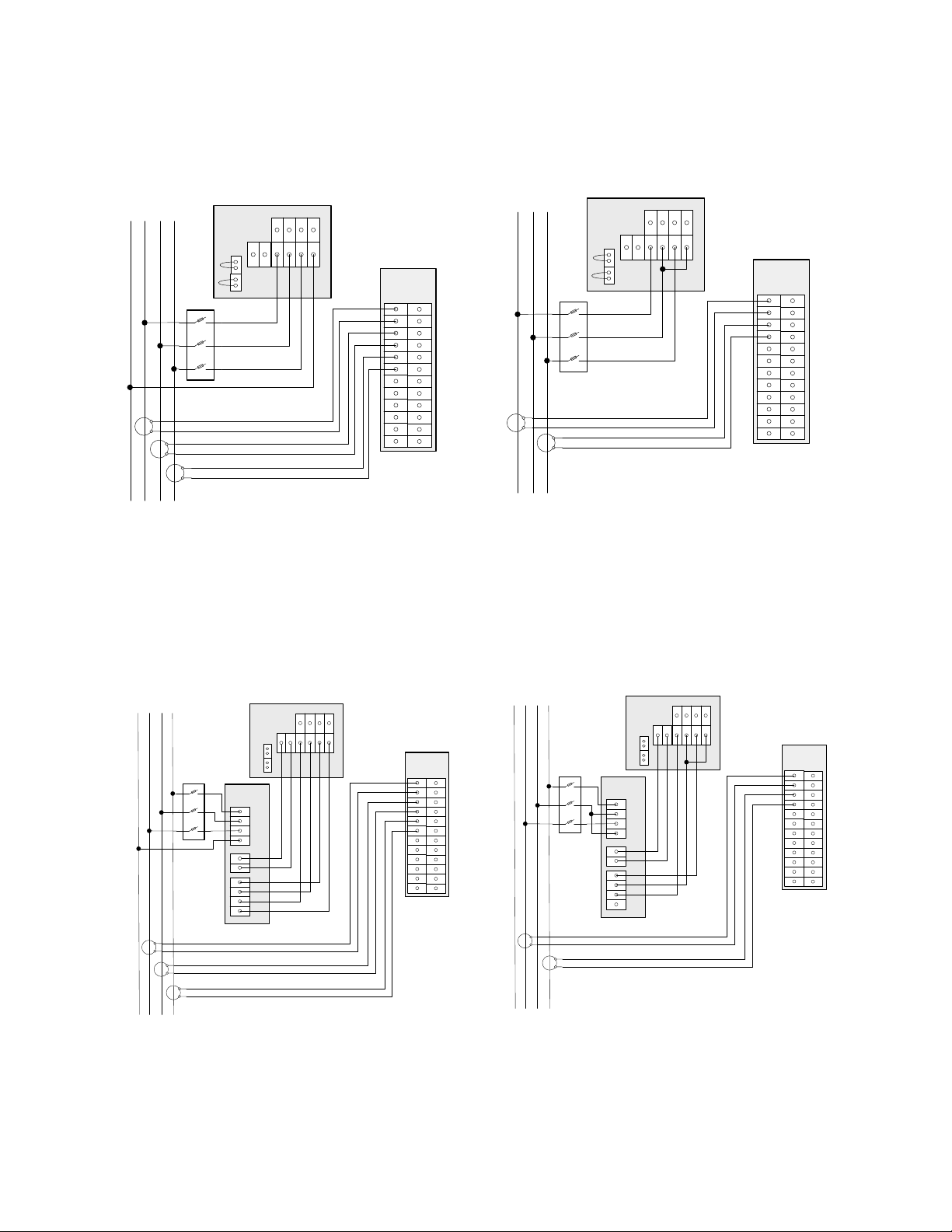
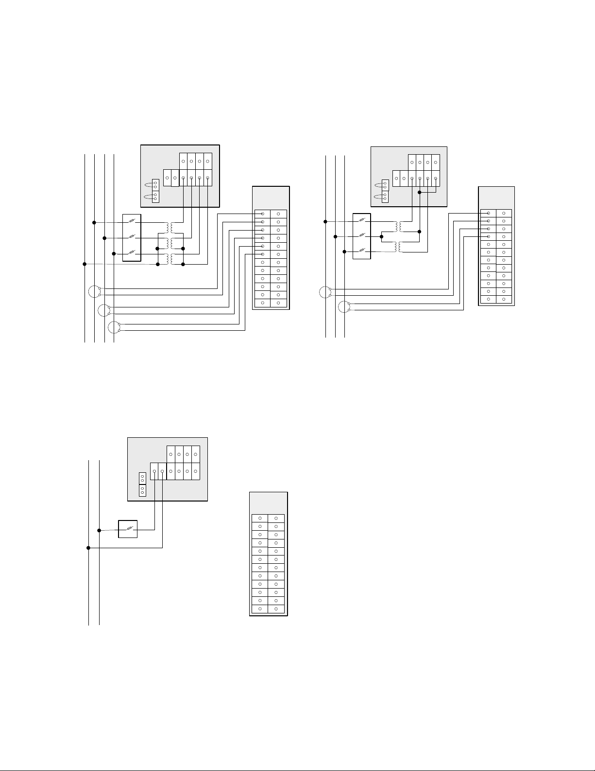
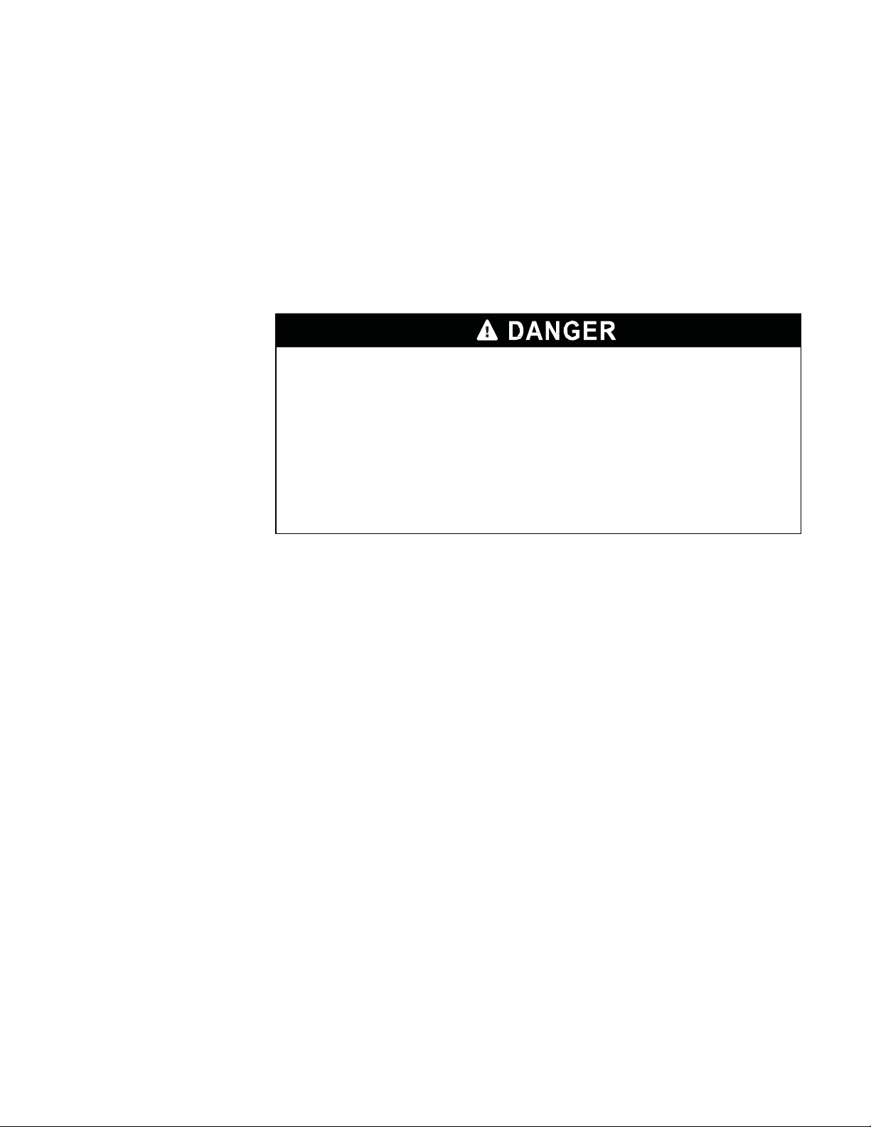
Figures 16 and 17 show typical installations with Triacta PT modules. Figures 18 and 19
show typical implementations with discrete external transformers.
Typically, external metering PTs are sized to convert from the panel’s line-to-line or line-toneutral voltages (ie 600VAC or 347VAC) down to 120VAC. The appropriate PT ratio (ie 5:1
or 2.89:1) must be programmed into the Triacta GATEWAY configuration as per the “Triacta
GATEWAY Flex Configuration Tool Guide” to provide correct meter readings.
Page 15

Triacta GATEWAY
© 2018 Triacta Power Solutions LP All Rights Reserved
15
15
Triacta GATEWAY CT / Pulse Wiring Modules
Current transformers and pulse output devices are connected to the Triacta GATEWAY via
specially designed self-shorting CT / Pulse Wiring Modules as shown below. The self-shorting
mechanism on each CT / Pulse Wiring Module is activated when the Triacta GATEWAY Meter
Head unit is not installed.
Each CT / Pulse Wiring Module supports 12 inputs pairs, numbered P1 to P12. The Triacta
GATEWAY Meter Base unit supports up to 4 CT / Pulse Wiring Modules for a total of 48 input
pairs. The number of inputs available of each type depends on the number of measurement
modules and CT / Pulse Wiring Modules installed in the meter.
The two inputs on each input pair are designated as + or -. If the CT / Pulse Wiring Module is
for CT connections, the X1 / X2 leads from each CT must respectively connect to the + / inputs. If the CT / Pulse Wiring Module is for pulse output devices, the + / - wires for each pair
connect as per the specific pulse output device type.
Each input pair on the CT / Pulse Wiring Module also has a colour pair designation that
matches on of the colour pairs available in an optional Triacta GATEWAY CT/Pulse
Termination Cable. Table 3 describes the termination cable wire pair colour scheme for each
input pair on the CT / Pulse Wiring Module.
The CT / Pulse Wiring Module is also available with a CT/Pulse Termination cable pre-wired
and over mold protected to the module as per the colour pair table.
Figure 5: CT / Pulse Wiring Module
Page 16
Triacta GATEWAY
© 2018 Triacta Power Solutions LP All Rights Reserved
16
16
Triacta GATEWAY Flex configuration
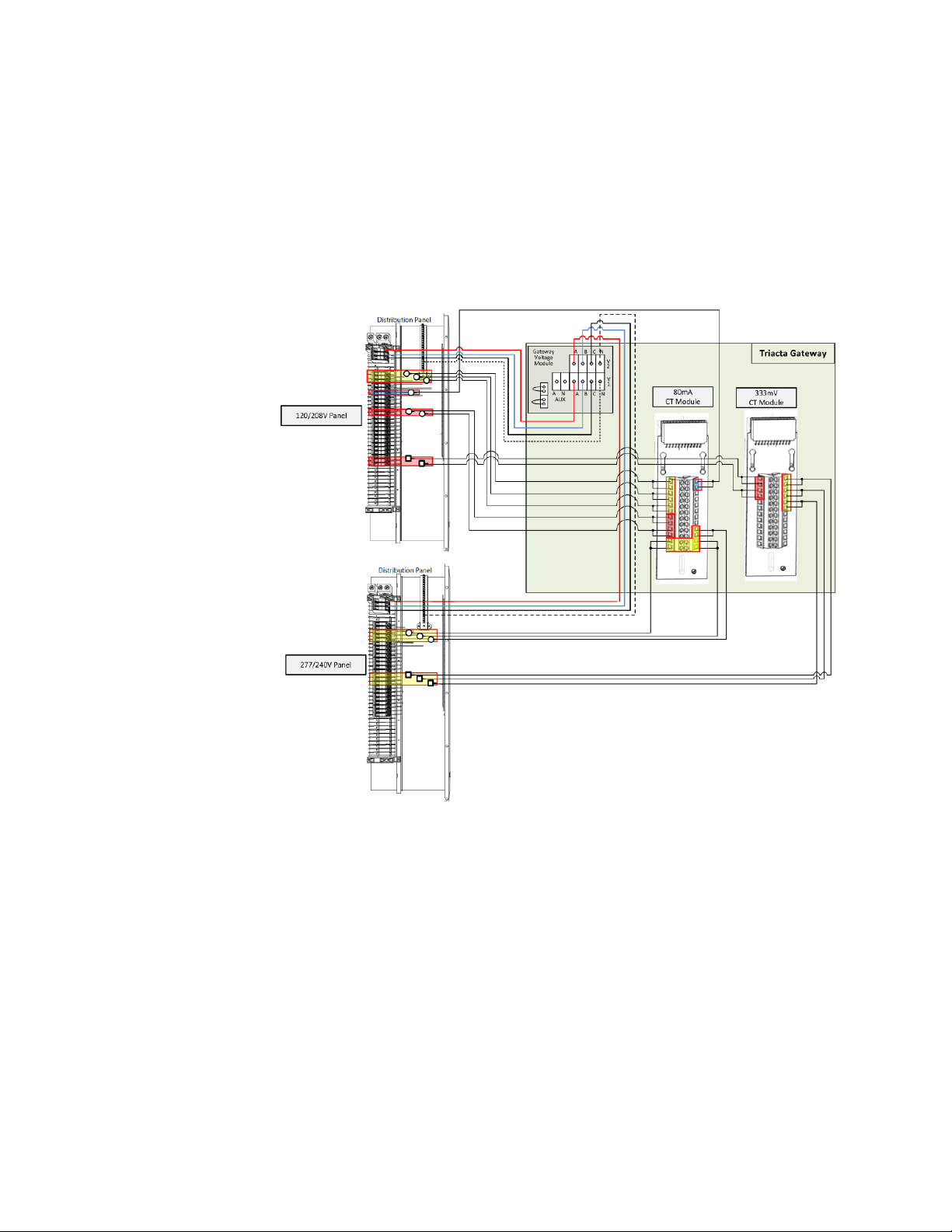
The following diagram illustrates how the Triacta GATEWAY could be connected to two
different voltage panels using two different types of CTs and different numbers of elements per
meter point from each panel.
Figure 6: Example Flex Configuration Wiring
Page 17

© 2018 Triacta Power Solutions LP All Rights Reserved
17
17
Triacta GATEWAY
Pre-Installation Instructions
The pre-installation checklist and site planning must be performed before installing the
equipment at the site.
Site Planning
1. Determine the number and types of meter points required by;
2. Determine the number of pulse inputs required
3. Determine the number of Triacta GATEWAY systems to be installed and ensure adequate
3. Determine the number and types of Measurement Modules required for each Triacta
4. Determine the number of control and/or sense voltage connections required and ensure
5. Determine the number of Ethernet drops required, and ensure they are installed before
# of elements - single-phase, two-phase, or three-phase.
# of different voltage references
CT types – 80mA, 100mA and/or 333mV
space. For clearances, see Figure 7.
GATEWAY system.
that an approved 15-Amp fused disconnect or breaker is provided for each connection.
installing the Triacta GATEWAY system.
Access to Power and Lighting
The installation site must be supplied with access to the main electrical panel and any subpanels. Portable or permanent lighting must be available to provide the installers with a clear
view of the equipment and of the installation environment. Each installation may vary
depending on physical site restrictions.
Page 18
© 2018 Triacta Power Solutions LP All Rights Reserved
18
18
Triacta GATEWAY
Installation Instructions
This section provides information about activities that must be performed to install the Triacta
GATEWAY in a single-phase 2-wire, single-phase 3-wire (network), three-phase 4-wire or 3ph
3wire delta application. The installation procedures must be performed in the following order:
Mount the Meter Base Module
The Triacta GATEWAY can be mounted on a wall as a complete system with the Meter
Head unit pre-installed or as just the Meter Base unit with the Meter Head unit to be
installed later. Figure 7 shows the general mounting layout for a Meter Base unit on its
own. There are three mounting holes as shown which are all accessible with or without the
Meter Head unit installed.
1. Mount the Triacta GATEWAY adjacent to the main circuit breaker box using the 1-inch
(25-mm) #8 screws. If mounting the unit on a plasterboard surface, use cylinder plugs.
2. Remove the front cover from the meter by removing the three screws with a #2 Phillips
screwdriver. Retain the cover and screws for later re-installation.
3. Mount the Triacta GATEWAY on the wall and secure it by inserting a screw in each
mounting keyhole and tightening the screws.
4. Use the provided washer on the top mounting screw when installing the Triacta
GATEWAY onto soft surfaces. Install the washer between the Meter Base unit and the
soft surface.
Figure 7: Meter Base Unit and PT module Mounting Layout, Dimensions and
Clearances
Page 19

© 2018 Triacta Power Solutions LP All Rights Reserved
19
19
Triacta GATEWAY
Install CT / Pulse Wiring Modules into the Meter Base Unit
In most cases the CT / Pulse Wiring Modules are shipped pre-installed in the Meter Base
module. If new modules are being added or replaced, insert them as shown in Fig 8 below.
Figure 8: Installing CT / Pulse Wiring Modules into the Meter Base Unit
Install disconnect devices for sense and control voltages
Each Triacta GATEWAY device must be connected to all sense and control voltages through
properly rated (15 Amp) disconnects or breakers that disconnect all line wires so that they can
be powered down. Each disconnect or breaker must be located within easy reach of the
meter operator, and must be labeled to indicate which set of device inputs it supplies power
to.
One disconnect is required for each separate sense or control voltage input.
For installations with multiple Triacta GATEWAY devices, the same disconnects can be
used to power multiple meters. Each disconnect must be labeled for all devices it supplies
power to.
The disconnect device or devices must meet IEC 60947-1, IEC 60947-3 and/or comply
with the local electrical code.
Connect Control and Sense Voltage Wiring
For a single-phase panel, use a 3-wire, 14 AWG (1.63 mm2), 90°C (194°F) cable.
For a three-phase Wye panel, use a 4-wire, 14 AWG (1.63 mm2), 90°C (194°F) cable.
For a three-phase Delta service, use a 3-wire, 14 AWG (1.63 mm2), 90°C (194°F) cable.
Metallic, flexible armored cable (BX cable) is recommended for commercial
installations.
Page 20

© 2018 Triacta Power Solutions LP All Rights Reserved
20
20
Triacta GATEWAY
CTs
PTs (3 phase)
Distribution Panel with 15A
Breaker or Disconnect
N A B C
X1
X2
H1
H1
H1
HAZARD OF ELECTRIC SHOCK, EXPLOSION, OR ARC FLASH
• Apply appropriate personal protective equipment (PPE) and follow safe
electrical work practices. See NFPA 70E.
• This equipment must only be installed and serviced by qualified electrical
personnel.
• Turn off all power supplying this equipment before working on or inside
equipment.
• Always use a properly rated voltage sensing device to confirm power is off.
• Replace all devices, doors and covers before turning on power to this
equipment.
• The meters must be
connected
to the sense voltage and control voltage through
a properly rated 15A breaker or voltage disconnect.
Failure to follow these instructions will result in death or serious
injury.
1. Before connecting the sense or control voltages, turn off the power to the circuit being
connected.
2. Always use a properly rated voltage sensing device to confirm power is off.
3. Connect the sense and control voltages voltage leads from the voltage disconnect/s to
the meter as described below for each service type:
4. If more than one meter is being installed, repeat this procedure for each additional meter
NOTE: The phase wiring sequence A, B, C between the Triacta GATEWAY meter and the
circuit breaker panel must match or the measurement readings will be incorrect. If the circuit
breaker panel does not designate phase A, phase B and phase C feeds, make your own
designation and use it for the rest of the installation.
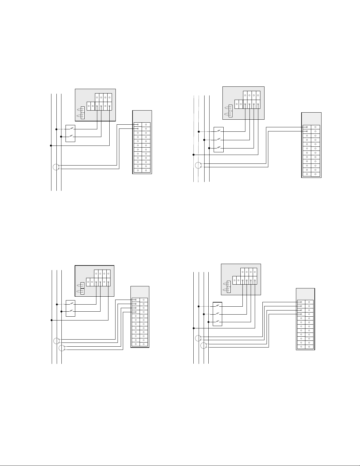
The following diagrams show the required voltage connections for various different panel
voltages and sample CT connections for different single element, 2 element and 3 element
circuit configurations.
Figure 9: Drawing Symbols for Voltage Connection Diagrams
Page 21
© 2018 Triacta Power Solutions LP All Rights Reserved
21
21
Triacta GATEWAY
V
2
A B C N
A B C N
A N
AUX
V
1
Gateway
Voltage
Module
CT1
X1
X2
N A B
Gateway
CT Wiring
Module
V
2
A B C N
A B C N
A N
AUX
V
1
Gateway
Voltage
Module
CT1
X1
X2
N A B C
Gateway
CT Wiring
Module
V
2
A B C N
A B C N
A N
AUX
V
1
Gateway
Voltage
Module
CT1
CT2
X1
X2
X1
X2
N A B
Gateway
CT Wiring
Module
V
2
A B C N
A B C N
A N
AUX
V
1
Gateway
Voltage
Module
CT1
CT2
X1
X2
X1
X2
N A B C
Gateway
CT Wiring
Module
Fig 10: Single Element Meter
Single phase – 3 wire Panel
120/240V or 230/460V
Fig 12: Two Element Meter
Single phase – 3 wire Panel
120/240V or 230/460V
Fig 11: Single Element Meter
3 phase – 4 wire Panel
120/208V, 230/400V, 240/416V or 277/480V
Fig 13: Two Element Meter
3 phase – 4 wire Panel
120/208V, 230/400V, 240/416V or 277/480V
Page 22
© 2018 Triacta Power Solutions LP All Rights Reserved
22
22
Triacta GATEWAY
V
2
A B C N
A B C N
A N
AUX
V
1
Gateway
Voltage
Module
CT1
CT2
CT3
X1
X2
X1
X2
X1
X2
N A B C
Gateway
CT Wiring
Module
V
2
A B C N
A B C N
A N
AUX
V
1
Gateway
Voltage
Module
CT1
CT2
X1
X2
X1
X2
A B C
Gateway
CT Wiring
Module
X1
X2
X1
X2
X1
X2
N A B C
Triacta
PT Module
C
B
A
N
C
B
A
N
Aux A
Aux N
V
2
A B C N
A B C N
A N
AUX
V
1
Gateway
Voltage
Module
Gateway
CT Wiring
Module
CT1
CT2
CT3
X1
X2
X1
X2
N A B C
CT1
CT2
Triacta
PT Module
C
B
A
N
C
B
A
N
Aux A
Aux N
V
2
A B C N
A B C N
A N
AUX
V
1
Gateway
Voltage
Module
Gateway
CT Wiring
Module
Fig 14: Three Element Meter
3 phase – 4 wire Wye Panel
120/208V, 230/400V, 240/416V or 277/480V
Fig 16: Three Element Meter
3 phase – 4 wire Wye Panel
With Triacta 347/600V PT Module
Fig 15: Two Element Meter
3 phase – 3 wire Delta Panel
230V or 240V Delta
Fig 17: Two Element Meter
3 phase – 3 wire Delta Panel
With Triacta 480V or 600V Delta PT Module
Page 23
© 2018 Triacta Power Solutions LP All Rights Reserved
23
23
Triacta GATEWAY
X1
X2
X1
X2
X1
X2
H1
H1
H1
N A B C
V
2
A B C N
A B C N
A N
AUX
V
1
Gateway
Voltage
Module
CT1
CT2
CT3
Gateway
CT Wiring
Module
V
2
A B C N
A B C N
A N
AUX
V
1
Gateway
Voltage
Module
N A
Gateway
CT Wiring
Module
V
2
A B C N
A B C N
A N
AUX
V
1
Gateway
Voltage
Module
CT1
CT2
X1
X2
X1
X2
A B C
H1
H1
Gateway
CT Wiring
Module
Fig 18: Three Element Meter
3 phase – 4 wire Wye Panel
With External PTs
i.e. 347/600V
Fig 20: Auxiliary Voltage Connection
(120VAC Min to 277VAC Max)
Fig 19: Two Element Meter
3 phase – 3 wire Delta Panel
With External PTs
480V or 600V Delta
Page 24
© 2018 Triacta Power Solutions LP All Rights Reserved
24
24
Triacta GATEWAY
Install and Connect CTs
Do not apply power until you have made these connections and followed all of the
instructions below:
• Connect all CTs to the appropriate circuits.
• Connect the CTs to the to the CT connection cable or directly to the CT / Pulse Wiring
Module.
• Use 18-22 AWG, 600V Insulated Butt Connectors for all CT wire to wire connections.
When installing current transformers of any type, follow these steps:
HAZARD OF ELECTRIC SHOCK, EXPLOSION, OR ARC FLASH
• Turn off all power supplying this equipment before working on or inside the
equipment.
• Always use a properly rated voltage sensing device to confirm the power is off.
• NEVER open circuit a CT; Connecting CTs to a Triacta GATEWAY CT / Pulse
Wiring Module will ensure that the CT wire pairs are always either shorted or
terminated by the Meter Head.
• Do not crimp the insulation when making the wire connections.
Failure to follow these instructions will result in death or serious injury.
i. Turn off the power feed to the panel where the CTs are being installed. Always use a
properly rated voltage sensing device to confirm power is off.
ii. Place the CTs on the desired circuit conductor wires
When installing solid-core CTs
i. Remove the feed wire from the circuit breaker,
ii. Place the CT over the wire, and
iii. Ensure that the orientation of the CT is correct with respect to the direction
of the current flow as indicated on the CT.
When installing split-core or Rogowski Coil CTs,
i. Open the CT and place the CT over the wire to the circuit breaker.
ii. Ensure that the orientation of the CT is correct with respect to the direction
of the current flow as indicated on the CT.
iii. Close the CT and Install cable ties if necessary to ensure that the CT is
held together securely.
iii. When connecting CTs to a CT cable,
i. Feed the CT cable from the Triacta GATEWAY meter into the panel through the
appropriate punch-outs with approved strain reliefs.
reconnect the wire
to the circuit breaker.
Page 25
© 2018 Triacta Power Solutions LP All Rights Reserved
25
25
Triacta GATEWAY
CT Type
Maximum Wiring
Distance / Minimum Wire gauge
80mA, 100mA or 333mV
300 ft (100 m) / 22 AWG
5A - With 5A:100mA
10 ft (3 m) / 18 AWG (from 5A CT to converter)
300 ft (100 m) / 22 AWG (from converter to meter)
ii. Strip the plastic sheaths on the cable to an appropriate length to expose the wire
pairs. Cut and strip the CT leads and wire pair leads to an appropriate length.
iii. Identify the proper circuit and phase of each CT and crimp the CT leads to the
correct X1 and X2 wire pairs in the CT cable for each meter element. (see Table 3 )
iv. Connect the CT cable to the CT / Pulse Wiring Module and secure it in place with
the retaining screws.
iv. When connecting CTs to a CT / Pulse Wiring Module
i. For each CT, feed two wires with the appropriate wire gauge and length from the CT
/ Pulse Wiring Module to the CT in the panel through the appropriate punch-outs
with approved strain reliefs. Ensure that each pair of wires is made up of two
different colours and that each pair of wires is clearly and uniquely identified at
each end (electrical panel and CT / Pulse Wiring Module).
ii. Cut and strip the CT leads and wire pair leads to an appropriate length to
expose the wire for crimping.
iii. Crimp the X1/X2 CT leads from each CT to one of the wire pairs.
iv. Strip the plastic sheaths on the CT / Pulse Wiring Module end of each wire to an
appropriate length to expose the wire.
v. Identify the proper circuit and phase of each CT connected to each wire pair
and insert the correct pair of wires into the X1 X2 (+/-) inputs of the correct
connection point in the CT / Pulse Wiring Module (CT1 –CT24) (see table 3)
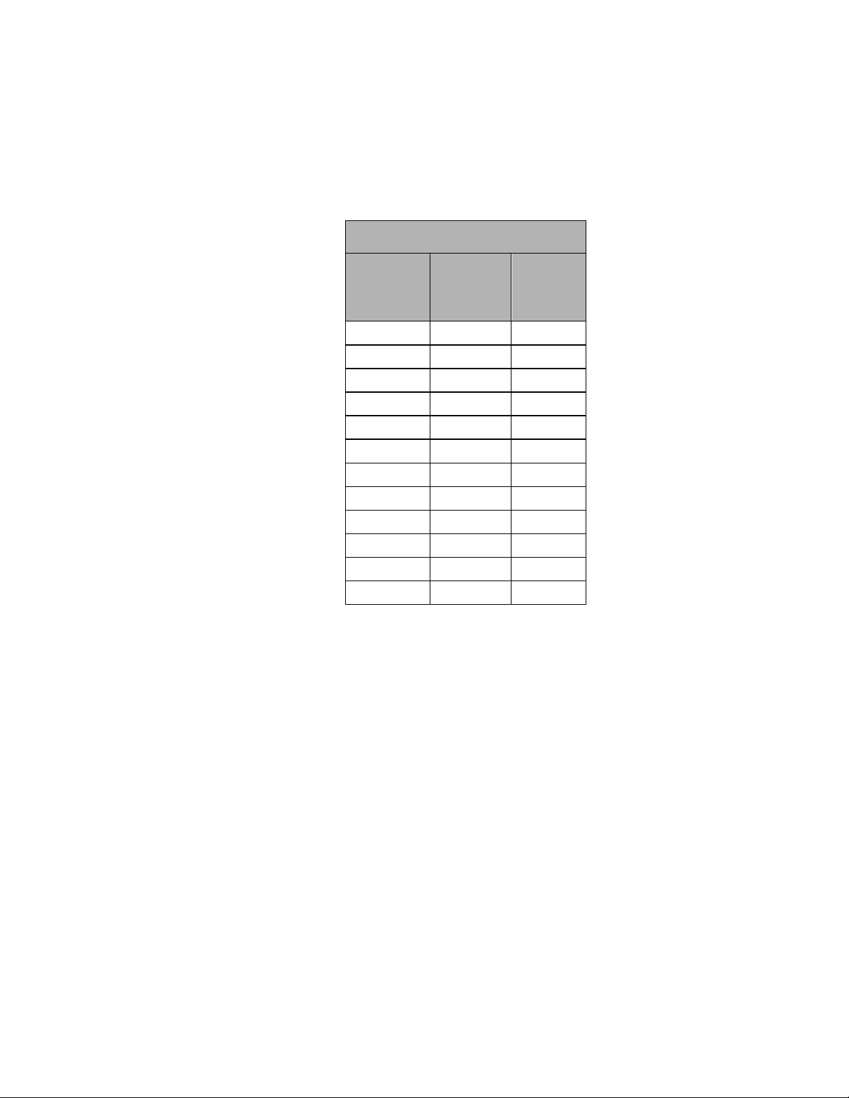
Table 2: CT wiring distances and wire gauges
v. When installing 5 Amp output CTs
iii. Connect the X1 and X2 leads of the 5A CT to a shorting device with the shorting
iv. Connect the X1 (red) and X2 (black) leads from the 5A side of the converter to the
Where 5A output CTs are required, they can be connected to a Triacta GATEWAY
80mA CT CT / Pulse Wiring Module using Triacta 5A:80mA CT converters.
i. Install or use an existing sealable metal enclosure outside of the electrical panel
within 10 feet of the 5A CTs.
ii. Mount a shorting device and one 5A:80mA CT convertor per 5A CT in the
enclosure. All 5A CTs should have a shorting device installed between the 5A CT
and the 5A:80mA CT convertor.
engaged.
other side of shorting device. Ensure that the connections from X1 and X2 leads
Page 26
© 2018 Triacta Power Solutions LP All Rights Reserved
26
26
Triacta GATEWAY
CT / Pulse Input Termination Cable
CT or Pulse
Pair #
Connect
CT X1 or
Pulse +
lead to:
Connect
CT X2 or
Pulse lead to:
1
Black
Red
2
Black
White
3
Black
Green
4
Black
Blue 5 Black
Yellow
6
Black
Brown
7
Black
Orange
8
Red
White
9
Red
Green
10
Red
Blue
11
Red
Yellow
12
Red
Brown
from the CT match the X1/X2 leads from the convertor.
v. Connect the X1 lead (white) and X2 (black) leads from the 80mA side of the
converter to a CT cable or a CT / Pulse Wiring Module as described in the
previous two sections
Table 3: CT / Pulse Wiring Module colour pair identification
Complete the installation record provided with each Triacta GATEWAY system to record
which CTs or pulse devices are connected to each input pair on each CT / Pulse Wiring
Module. See Figure 23 for an example.
Connect Pulse Inputs
Connect each external pulse output device to be monitored (gas, water, BTU meter, …) to a
separate pulse input pair (+/-) on any of the CT / Pulse Wiring Modules designated as a pulse
input module.
Each pulse input is compatible with both dry (reed) and solid-state Form A contacts.
When the pulsing device provides solid-state form A outputs, the negative terminal from the
source device must be connected to the negative (-) terminal of the Triacta GATEWAY pulse
in terminal block.
When the pulsing device provides dry contact (reed) pulse outputs the pulse input wire pairs
are not polarity-sensitive.
The maximum input pulse rate is 200 Hz (maximum), and the minimum input pulse width is
2.0 ms.
Page 27
© 2018 Triacta Power Solutions LP All Rights Reserved
27
27
Triacta GATEWAY
LED
Colour
Description
Green
Connection State:
On – An active device has been detected
Off – No active device is connected.
Amber
Activity indicator:
Flashing On – Data activity detected on the interface
Off – No network activity detected.
The recommended wiring for pulse input pairs is 22 AWG shielded twisted pair wires for distances
up to 300 ft (100 m). Use larger gauge wire for larger distances up to 600 ft (200 m).
For each external pulse generating device, document the Wiring Module number and the wire pair
it is connected to, and the units per pulse output of the device.
Connect the Ethernet Cable
Connect the Triacta GATEWAY to a 10/100BaseT 802.3-2002 compliant IP network or
device by connecting a CAT5 Ethernet cable to the RJ45 Ethernet port on the Meter Head
unit. The Ethernet port enables TR3/TR5 data reporting and BAS Modbus IP or (future)
BACnet TCP/IP services to the Triacta GATEWAY device.
Route the Ethernet cable through one of the punch-outs in the bottom of the Meter Base.
There are two LEDS on the RJ45 jack which will indicate the status of the Ethernet
connection as shown in the following table:
Table 4: Ethernet Port LED Indicator Status
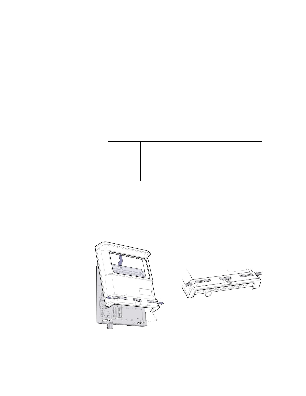
Install the Cover
The cover is installed from the top by holding it at a shallow angle and dragging down until the
inside of the drip cover catches the flange at the top of the Meter Base.
Figure 22: Installing the cover
Page 28

© 2018 Triacta Power Solutions LP All Rights Reserved
28
28
Triacta GATEWAY
Move both locking bars out to each side.
Centre the cover over and above the base and move the cover down at a shallow angle until
the 'v' groove at the cover locates on the top mounting stud
All conduit adapters must be firmly seated to ensure that cover closes.
When the cover is firmly seated, slide the locking bars inward to secure the cover. Pull up on
each bottom corner to ensure that the locking bars are seated properly.
When the cover locking bars are pushed in, the utility seal holes should be in alignment
allowing for a Service Utility seal wire to be installed as shown.
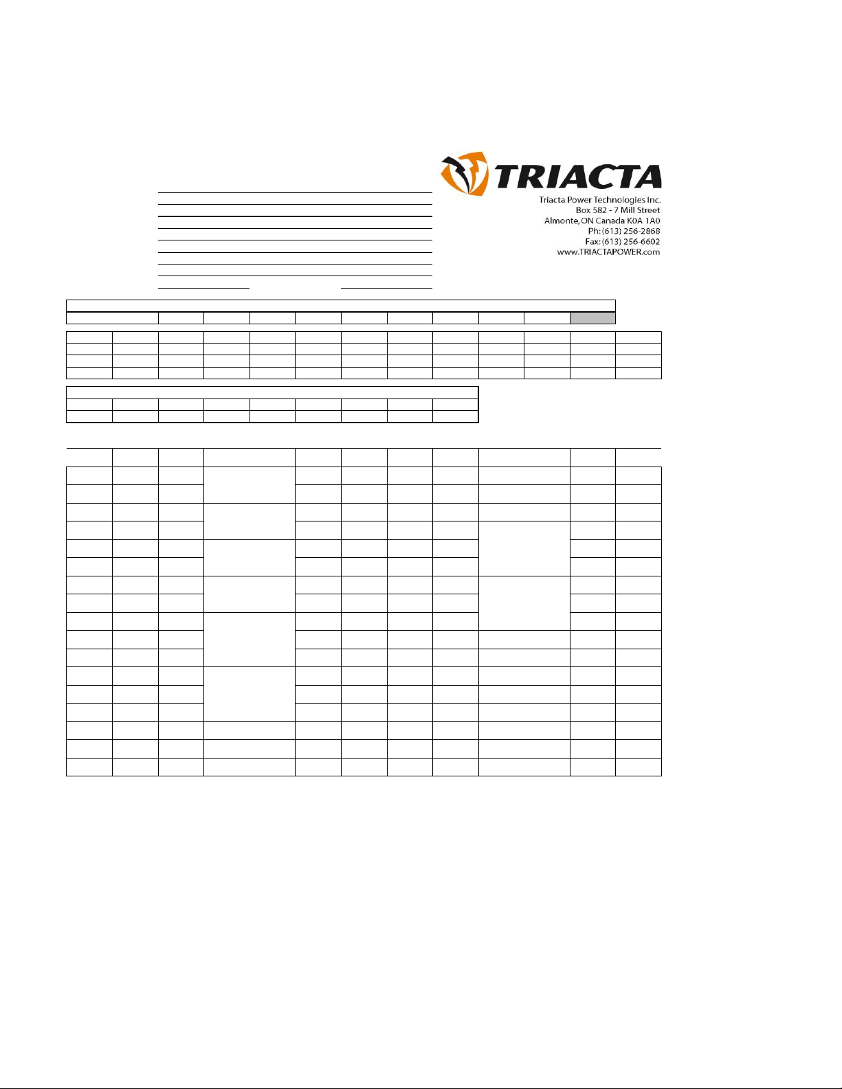
Record the Meter Map
If an Installation Record was not provided with the metering equipment to direct the
installation the final step in the installation process is to complete the Installation Record to
record the mapping of the circuits being measured to the meter points. A copy of Figure 23,
which is organized to resemble a breaker panel, is provided with each Triacta GATEWAY,
and is to be completed and delivered to your system administrator.
Page 29
© 2018 Triacta Power Solutions LP All Rights Reserved
29
29
Triacta GATEWAY
PowerHawk GXXXX Installation Record
Panel Description:
Customer:
Address:
City:
Prov/State:
Postal/Zip Code:
Inspection Date:
Inspector:
PowerHawk MAC PowerHawk Serial #:
Installation
Volts 120 Amps 600 Hz 60 Phase 3 Wire 4 Service Y
Units
Insp # Maker Badge # Serial # Type Volts Amps Multi Kh Phase Wire Elements Sealed
PTs
Meter Maker Serial # A Serial #B Serial # C Type Primary Secondary PT Ratio
Note: Connect the X1 lead (positive Lead) of the CT to the first colour of each wire pair (X1 CT input)
Wire Mod. #
CT #
CT Amps circuit phase circuit CT Amps
CT #
Wire Mod. #
1
1 100 1 2 20 1 2
1
2 100 3 4 20 2 2
1
3 100 5 6 20 3 2
1
4 100 7 8 100 4 2
1
5 100 9 10 100 5 2
1
6 100 11 12 100 6 2
1
7 100 13 14 400 7 2
1
8 100 15 16 400 8 2
3
1 200 17 18 400 9 2
3
2 200 19 20
3
3 200 21 22
3
4 200 23 24
3
5 200 25 26
3
6 200 27 28
29 30
31 32
33 34
Main electrical Room
ABC Properties
100 Main St.
Ottawa
Ontario
K0A 1A0
July 1st 2017
0021B6000001
117010001
Laundry 1
Description
Laundry 2
Laundry 3
Suite 100
Suite 103
Penthouse 1
Penthouse 2
Air Handler
Elevator
Description
Suite 101
Suite 102
Figure 23: Installation Record (sample shown)
Page 30
© 2018 Triacta Power Solutions LP All Rights Reserved
30
30
Triacta GATEWAY
MAINTENANCE
Do not perform any operation or maintenance procedures that are not described in this
product documentation. No preventive maintenance is required on any of the equipment.
Visually inspect the equipment yearly and ensure it is free of dust or other particles. If
necessary, wipe with a clean cloth. Individual components are not user-serviceable and must
be returned to Triacta Power for repair.
Fuse Replacement
HAZARD OF ELECTRIC SHOCK, EXPLOSION, OR ARC FLASH
• Apply appropriate personal protective equipment (PPE) and follow
safe electrical work practices. See NFPA 70E.
• Turn off all power supplying this equipment before working on or
inside equipment.
• Always use a properly rated voltage sensing device to confirm the
power is off.
• Replace all devices, doors and covers before turning on power to
this equipment.
Failure to follow these instructions will result in death or serious
injury
1. Turn off all sources of power before attempting to replace
the fuse. Always use a properly rated voltage sensing
device to confirm the power is off.
2. Remove the outer cover from the unit.
3. Locate fuse F1 on the Triacta GATEWAY Voltage Module
as shown in Figure 4.
4. Replace fuse F1 with a fuse that meets the specifications
listed in Table 1.
DANGER
Page 31
© 2018 Triacta Power Solutions LP All Rights Reserved
31
31
Triacta GATEWAY
Meter Head Servicing or Replacement
Before removing the Meter Head, be sure to turn off all the power feed/s to the Triacta
GATEWAY Meter Base unit. Always use a properly rated voltage sensing device to confirm
power is off.
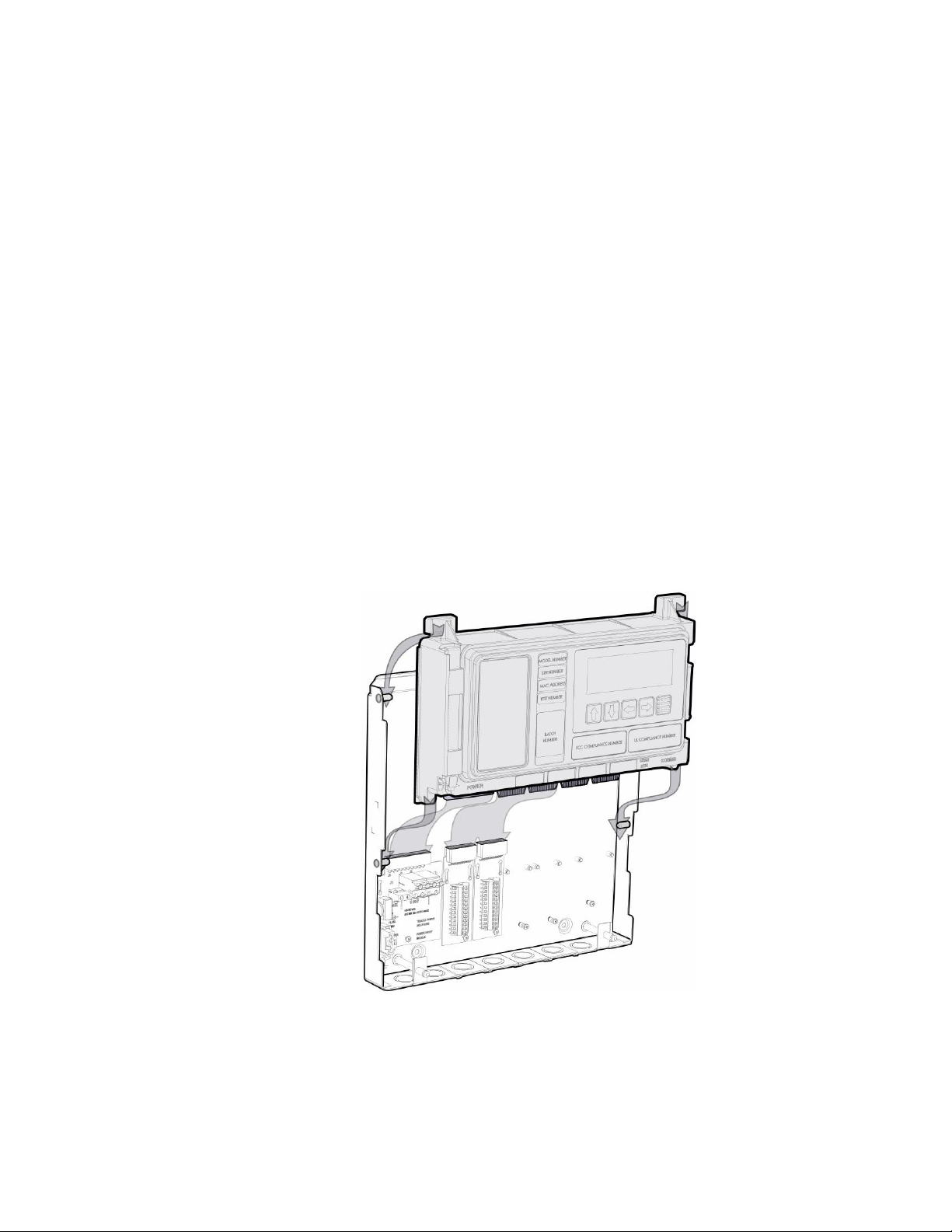
Push up firmly on the Meter Head to disconnect the Meter Head edge connectors from the
Voltage, Wiring and Communication Modules installed in the Meter Base unit.
Slide the Meter Head up so that the alignment tabs on the Meter Head go behind the alignment
pins on the Meter Base unit as shown in the diagram below.
To replace/reinstall the Meter Head, slide the Meter Head down from above so that each of the
alignment tabs on the Meter Head unit go behind the alignment pins on the Meter Base as
shown in the diagram below.
Push down firmly on the Meter Head unit to fully insert the Meter Head unit edge connectors
into the Voltage, Wiring and Communication Modules installed in the Meter Base unit.
In most cases the Triacta GATEWAY will be shipped with the Meter Head unit pre-assembled
into a Meter Base unit. Alternately, the Meter Base unit can be pre-installed early in the
construction phase (ie as the electrical panels are being built) and the Meter Head unit can be
inserted later when the installation is ready to be commissioned.
Figure 21: Inserting the Meter Head Unit
Page 32
© 2018 Triacta Power Solutions LP All Rights Reserved
32
32
Triacta GATEWAY
CT Sensor
Module
Solid core
CTs
Split core
CTs
Rogowski Coil
CTs
Maximum wiring
distance/
Wire gauge
80mA
80mA
300 ft (100 m) / 22 AWG
5A (with
5A:80mA
converter)
5A (with
5A:80mA
converter)
10 ft(3 m) / 18 AWG (from 5A
CT to converter
300 ft (100 m) / 22 AWG (from
converter to meter)
100mA
100mA
300 ft (100 m) / 22 AWG
333mV
0.333 V
0.333 V
300 ft (100 m) / 22 AWG
Appendix 1: Current Transformers Overview
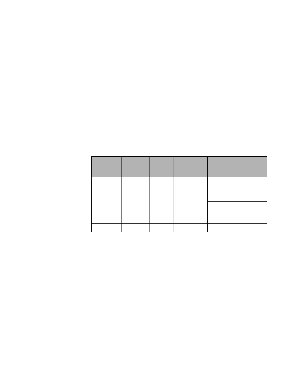
Current transformers (CTs) measure the current flowing through a wire. They are installed
around each wire for each circuit to be monitored and connected to the Triacta GATEWAY
via a Triacta GATEWAY CT / Pulse Wiring Module.
CT Types
Current transformers are classified by their secondary output (80 mA, 100 mA, 5A, or
333 mVolt) and by their physical appearance (solid core, split core, or rope).
Table 5 lists the Triacta GATEWAY CT Measurement Modules and the types of CT that
can be used with each module. The table also indicates the maximum distance and
corresponding wire gauge for connecting each type of CT to the Triacta GATEWAY.
For Triacta GATEWAY release 1.0, Rogowski Coil CTs must have an external integrator.
Future releases will provide an internal integrator function which will allow the Rowgowski
Coil CTs to be directly connected to the Triacta GATEWAY.
Table 5: Current transformer specifications
As shown in table 5, 5 Amp secondary CTs can work with the Triacta GATEWAY by using
Triacta 5A:100mA or 5A:80mA CT convertors (figure 24). One convertor is required for
each 5A secondary CT.
Figure 24: 5A solid core CT with 5A:80mA converter and shunt connector
Page 33
© 2018 Triacta Power Solutions LP All Rights Reserved
33
33
Triacta GATEWAY
CT Orientation
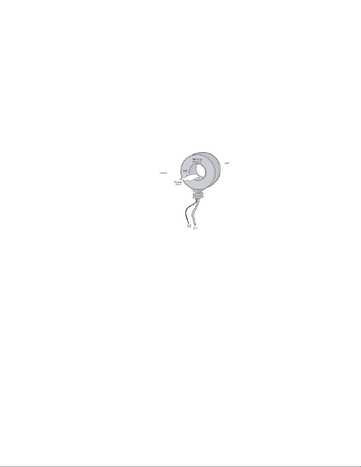
When installing each CT, ensure that the orientation of the CT matches the direction
of the energy flow as indicated on each CT.
The direction of energy flow is identified by either;
1) a label - “This side towards source”,
2) an arrow - the arrow points away from the source, or
3) a stamp or label indicating which side is H1 - the H1 side faces towards
the source.
If the orientation is backward, the meter readings will be incorrect.
Figure 25: Triacta 100 or 80 mA current transformer
Wiring polarity
CT
Each CT has two output wires or posts. One output is X1 (positive) and the other output is X2
(neutral). The X1 output is normally labeled directly on the CT. It may be explicitly identified
as X1, or it may be identified with a dot. If there is no X1 marking, refer to the CT
manufacturer’s documentation to determine the proper polarity.
The X1/X2 outputs from each CT for each circuit must be connected to the X1/X2 inputs of
each corresponding CT input connection on the appropriate Triacta GATEWAY CT input
module.
When installing CTs in a panel, ensure that all CT wiring is labeled with the proper
X1/X2 designations, or that it follows a standard X1/X2 colour pair mapping. If the
CT wiring polarity is incorrect, the meter readings will be incorrect.
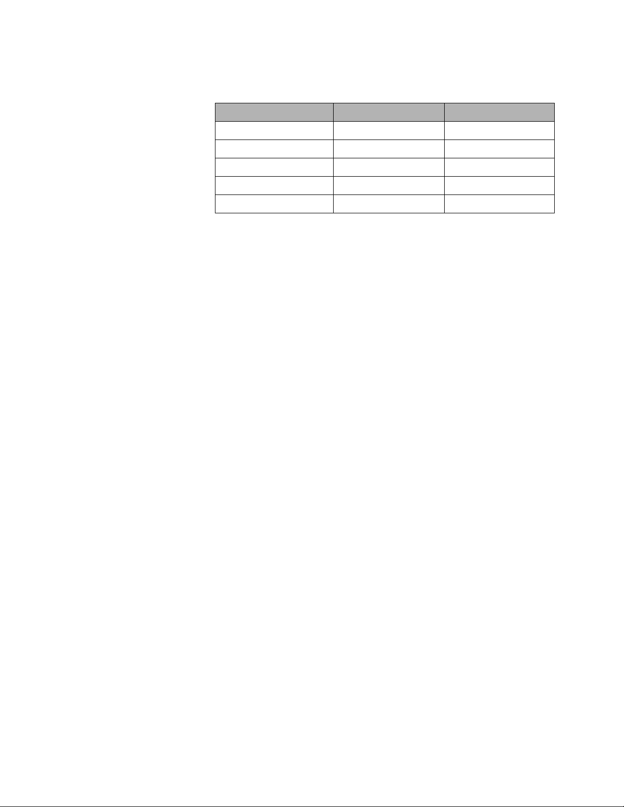
CT Phasing
Depending on the number of voltage phases and the number of wires connected to each
circuit being measured, a minimum of one, two or three CTs are required for each meter point
to correctly measure energy usage by the circuit.
Page 34
© 2018 Triacta Power Solutions LP All Rights Reserved
34
34
Triacta GATEWAY
Voltage phases and wiring
Number of CTs required
Phases typically used
Single-phase 2-wire
1
A, B or C
Single-phase 3-wire
2
A-B
Two-phase 3-wire
2
A-B, C-A, B-C
Three-phase 3-wire Delta
2 (optionally 3)
A-C
Three-phase 4-wire
3
A-B-C
Table 6: CT Phasing
Ensure that the correct number of CTs are properly installed on each circuit, and that the
X1/X2 wire pair connected to each CT is labeled with the correct circuit name and phase.
Ensure that the phase of the wire that each CT is installed on matches the sense voltage
input phase connections as shown in the relevant voltage connections drawings.
Note that standard circuit wire phase colours and/or breaker positions do not always
match from one panel or circuit breaker to another. It is recommended that the phasing is
verified from the circuit to the sense voltage source with a voltmeter and not just by visual
inspection.
If the CT phases do not match the sense voltage phases, the meter readings will be
incorrect.
CT Shorting and Termination
The X1 and X2 outputs for all 5A, 100mA or 80mA CTs MUST always be either shorted or
terminated to a meter when the circuits that they are installed on are energized. Failure to
terminate or short a CT on an energized circuit can cause dangerous voltages on the open CT
leads that can result in a fire hazard and/or catastrophic damage to the CT.
The CT / Pulse Wiring Modules have built-in shorting that is activated whenever the
Triacta GATEWAY Meter Head unit is not installed.
5A CTs should have their own shorting/shunt connector that allows each set of 5A CTs to be
independently shorted at the 5A secondary (see Figure 24). For safe access, the 5A
converters and shorting should be installed in a dedicated accessible metering compartment
located in a main distribution panel, or in a separate metal enclosure.
CT/Pulse Wiring Modules
Two types of CT/Pulse Wiring modules are available for the Triacta GATEWAY. A
CT/Pulse Wiring - Screw Terminal module and a CT/Pulse Wiring - 12Pair Cable Module.
The CT/Pulse Wiring - Screw Terminal module has built-in screw terminal termination
blocks for direct connections of up to 12 CT wire pairs. W hen connecting CTs to this
module each CT is connected to one of the wire pair connection points labeled from P-1
to P-12. The X1 and X2 inputs for each CT are labeled +/- for each wire pair connection
point.
The CT/Pulse Wiring - 12Pair Cable Module provides a 4 meter long cable with 12
uniquely colour coded wire pairs. Each CT is connected to one of the twisted-pair colour
wire pairs in the 12-pair CT connection cable. The colour codes for the X1 (positive) and
Page 35
© 2018 Triacta Power Solutions LP All Rights Reserved
35
35
Triacta GATEWAY
Metering configuration
CT naming designation
(meter#-element#)
All single-element meters
1-1
2-1
3-1
...
48-1
All two-element meters
1-1, 1-2
2-1, 2-2
3-1, 3-2
...
24-1, 24-2
All three-element meters
1-1, 1-2, 1-3
2-1, 2-2, 2-3
3-1, 3-2, 3-3
...
16-1, 16-2, 16-3
X2 (neutral) connections for each of the 12 CTs are listed in Table 3. The first colour of
each colour pair is connected to X1, and the second colour of each colour pair is
connected to X2 of each CT.
Typically, the CT/Pulse Wiring - 12Pair Cable Module would be used when all CTs are
located in the same distribution panel. The CT cable can be easily routed from the
Triacta GATEWAY to the distribution panel and the CTs can then be direct connected to
the CT cable inside the panel.
If CTs are located in different panels, or if there is a very long distance from the CTs to
the Triacta GATEWAY, it may be more desirable to route separate wire pairs from each
CT direct to the CT/Pulse Wiring - Screw Terminal module.
If more than one type of CT Measurement Module (ie 80ma, 100mA or 333mV) is
installed in the METER HEAD unit, ensure that all of the CTs on each CT / Pulse Wiring
Module are of the same type. Do not mix CTs of different types on the same CT/Pulse
wiring module. The position of each CT / Pulse Wiring Module in the Meter Base unit for
each type of CTs much also match the position of the corresponding CT Measurement
module in the METER HEAD unit.
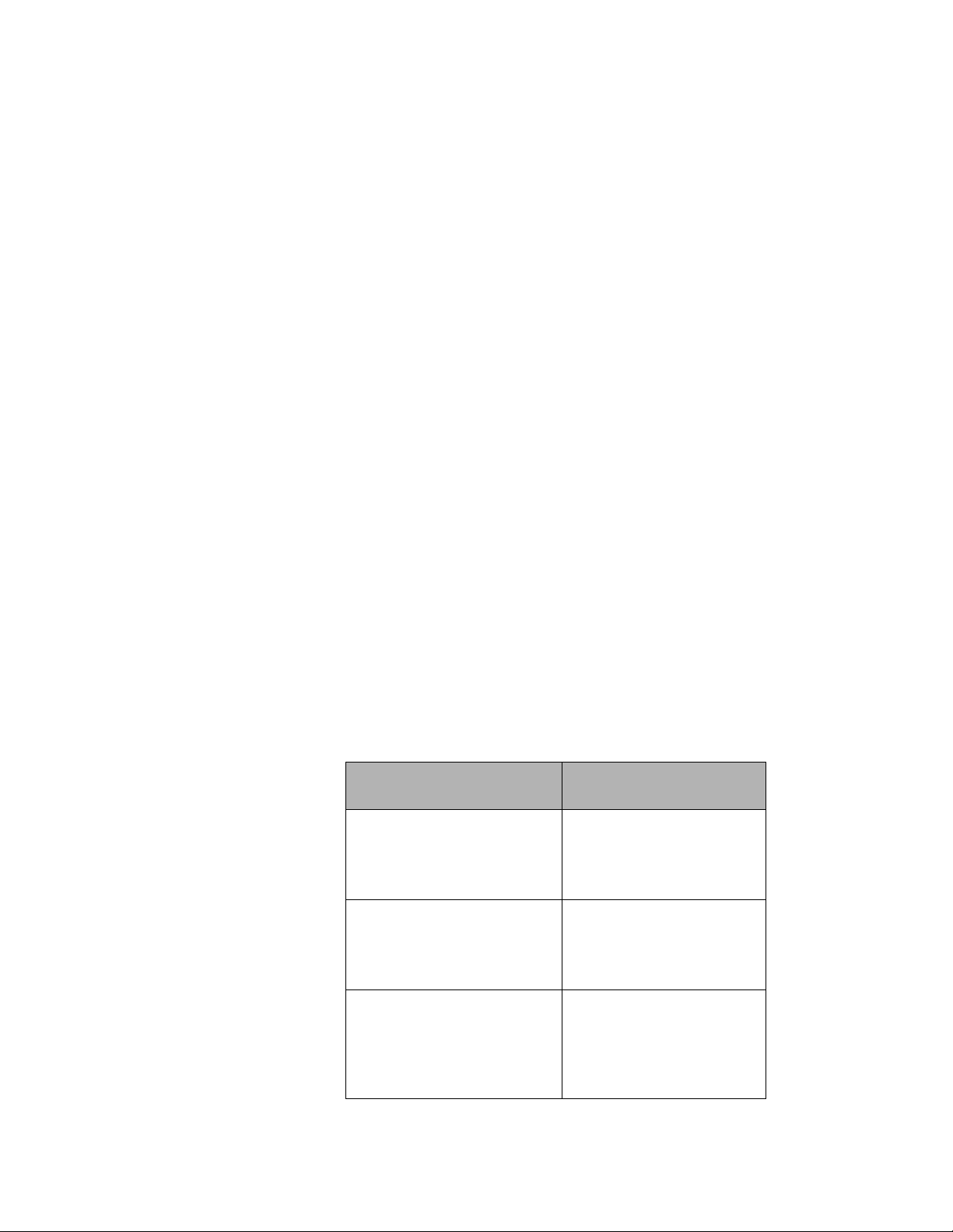
CT Naming designations
Each CT is physically identified by the CT/Pulse wiring module slot and wire pair it is connected
to, and then logically identified (named) by a meter number and an element number (meterelement).
The Triacta GATEWAY can support any combination of single element, two element and/or
three element meters in any order, up to a total of 12, 24, 36 or 48 elements depending on
the number of installed CT modules. The number of meters and the number of elements per
meter are determined by the metering configuration programmed into the meter.
The following table shows some sample CT naming configurations
Table 7: CT Naming
Page 36

© 2018 Triacta Power Solutions LP All Rights Reserved
36
36
Triacta GATEWAY
Mixed element meters
1-1, 1-2, 1-3
2-1, 2-2, 2-3
3-1, 3-2
4-1
5-1
6-1,6-2
…..
n-1, n-2, n-3
Page 37
© 2018 Triacta Power Solutions LP All Rights Reserved
37
37
Triacta GATEWAY
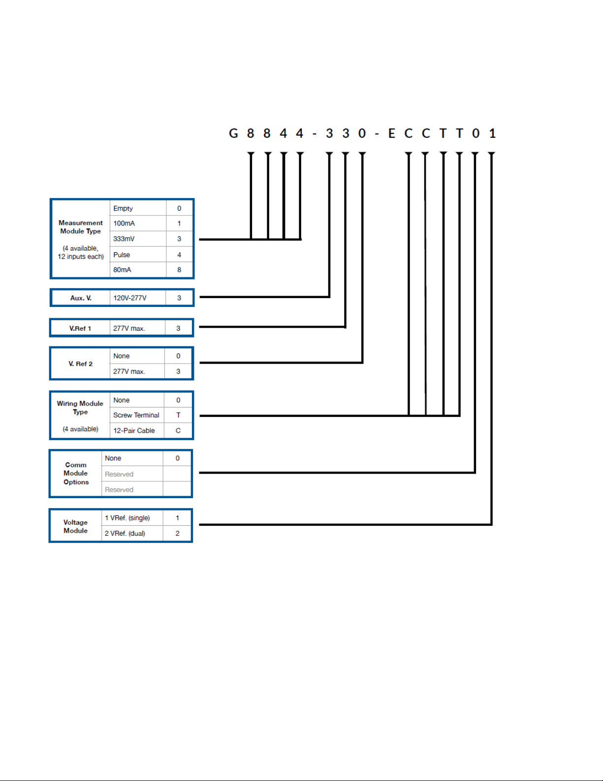
Appendix 2: Triacta GATEWAY Part Number Configuration Guide
Page 38
© 2018 Triacta Power Solutions LP All Rights Reserved
38
38
Triacta GATEWAY
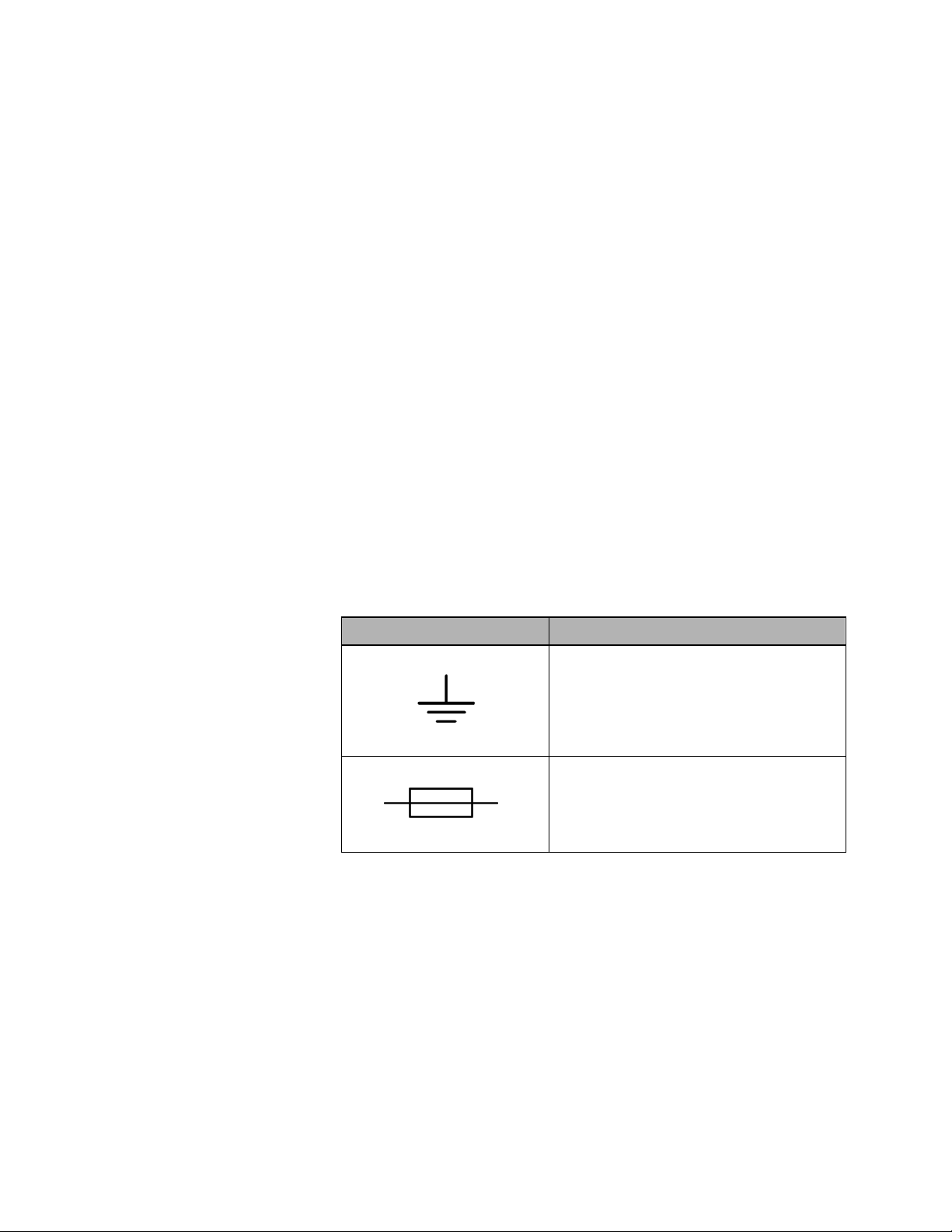
Symbol
Description
Indicates the supply wire protective earth, also known as
chassis ground, for the primary ground
This symbol indicates a replaceable fuse.
Equipment servicing and access
The information in this section must be considered as a mandatory requirement, and must
be strictly adhered to when installing and operating Triacta GATEWAY.
Access to equipment
The equipment must be accessible to authorized personnel only. Equipment must be installed
in areas where access can be restricted.
Servicing the equipment
No preventive maintenance is required on any of the equipment. Visually inspect the
equipment yearly and ensure it is free of dust or other particles. If necessary, wipe with a
clean cloth.
Component servicing
Individual components are not user-serviceable, and must be returned to Triacta Power
Solutions for repair. If an equipment fault occurs, do not attempt to repair the faulty component.
All maintenance activities should be performed by qualified personnel only. Do not perform
any operating or maintenance procedures that are not described in the product
documentation.
Graphical symbols
Table 9 shows the graphical symbols that appear on the equipment.
Table 9: Graphical symbols that appear on equipment
Page 39

Page 40

Triacta Power Solutions LP
130 Industrial Ave, Unit 100
Carleton Place, Ontario K7C 3T2
www.Triacta .com
Electrical equipment should be installed, operated, serviced, and maintained only by qualified
personnel. No responsibility is assumed by Triacta Power for any consequences arising out of the
use of this material.
930-148-01-A.00 © 2018 Triacta Power Solutions All Rights Reserved
11/2018
 Loading...