

Page 1
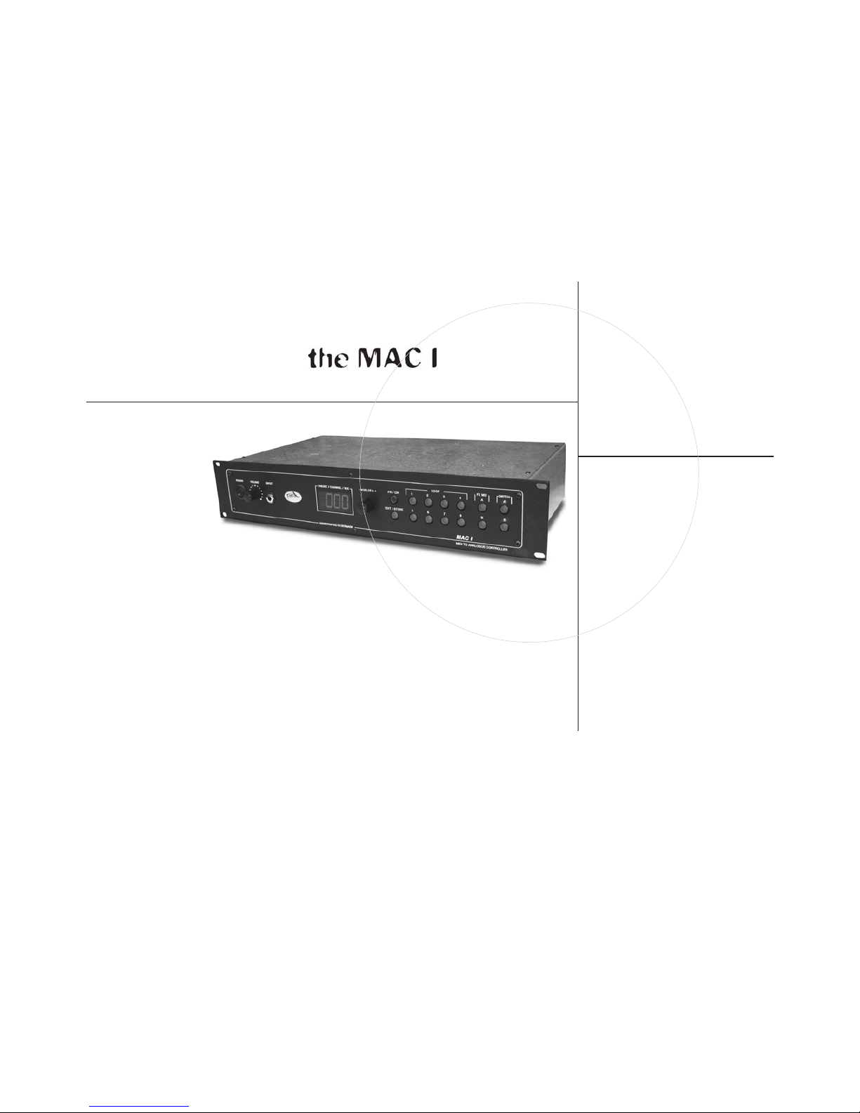
“ T A K E E F F E C T S C O N T R O L A S T E P F U R T H E R ”
MIDI TO ANALOGUE CONTROLLER
USER’S MANUAL
Page 2
2
Introduction 3
Front panel features 4
Rear panel features 5
Modes 6
Editing/programming 6
Midi hookup 7
VCA control 7
Setup ex. 1: The Mono Guitar System 8
Setup ex. 2: The Stereo Guitar System 9
Specications 10
MAC 1 block diagram 11
Table of contents
Page 3

3
Congratulations on the purchase of your new MAC 1
T-Rex grants a 2-year warranty against defective parts or workmanship.
In the event of a defect, please contact the nearest T-Rex dealer.
The MAC 1 is an analogous programmable switching/line mixer module that is designed for use in stereo or
mono guitar and bass rigs.
The module provides total control over modern and vintage pedals, midi and non-midi processors/effects, amp
selection, channel switching and VCA-control.
MAC I is in principle divided into 4 separate sections. These sections will remain separate until connected via
cables on the rear panel.
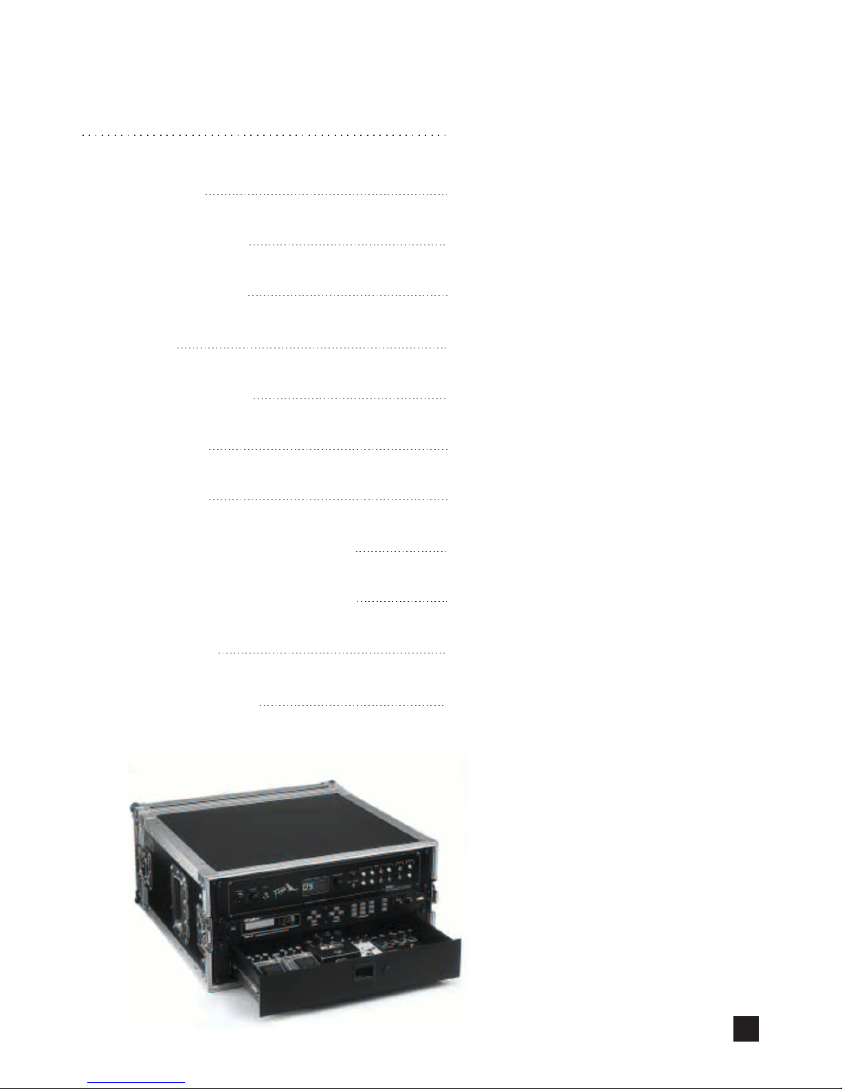
1) The Loop section:
MAC 1 offers 8 serial loops (6 in mono - 2 in stereo).
The audio path contains no active circuitry to insure no loss of tone and complete transparency to your
sound.
All loops can be switched on/off independently in every possible conguration.
Use the Loop section for simple in/out switching of your vintage-stomp boxes, preamps, EQ-units, compressors
etc. and/or as an amp selection control for multi amp set-ups for switching between up to 8 different amps.
2) The Line Mix section:
Contains 2 parallel stereo loops that are 100% programmable from 0 (fully dry) to 127 (max effects).
Use the FX line mixer to blend the signal from effects processors, chorus units, delay, reverb and similar time
based effects with the direct signal.
Both line mixers can be real time controlled with an expression pedal.
3) A/B switching:
The A/B switching is used to control footswitch able devices like a channel switching preamp,
combo/head.
4) VCA-control:
The VCA-control is an active volume control that enables you to control your overall stereo/mono volume
with an expression pedal via your MIDI board.
If you are fed up with dancing ballet on top of a tangled mess of pedals and cables in order to change sounds,
the MAC 1 provides you with a rst class opportunity to clean up the stage area in front of you.
Tug your stomp boxes away in your rack and get a clean, shorter signal path avoiding unnecessary cable lengths
causing signal loss, “thin” sound and excessive noise.
Each loop is controlled by a gold plated relay and is the perfect place to connect your stomp boxes and effects
processors in their natural order.
Welcome
Page 4
4
F7
F10
F2
F3
F4 F5 F6
F8 F9 F11
F12
F1
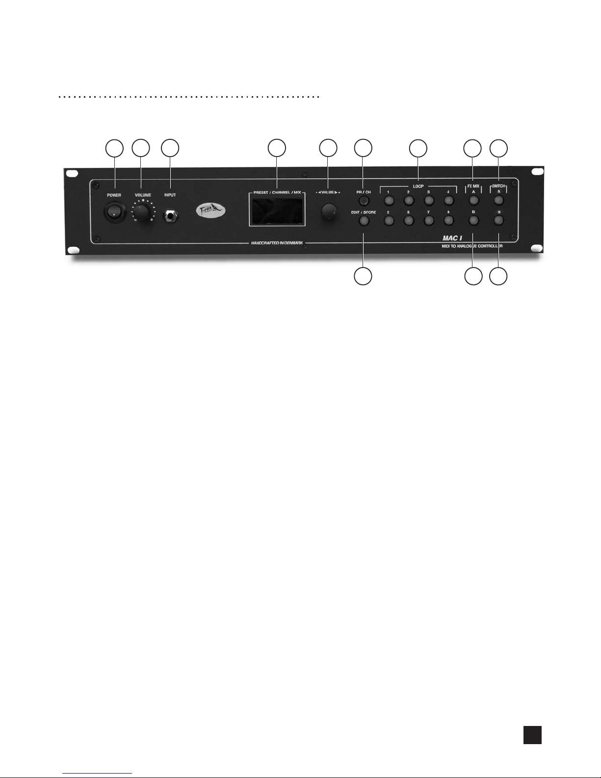
Frontpanel features
F1) POWER: Turns MAC 1 on/off
F2) VOLUME: Adjusts the overall volume level from the VCA left and right outputs
(Only active when the VCA-control is hooked up.)
F3) INPUT: Front panel input socket.
F4) DISPLAY: The display has 4 characters and shows patch-number, MIDI channel or mix-
value, depending on the mode (PLAY mode, EDIT mode or MIDI mode)
F5) VALUE WHEEL: Use the value wheel to change the values of a parameter.
-In PLAY mode you can scroll between the 99 patches.
-In EDIT mode the value wheel controls the mixer levels in FX mix A and
FX mix B.
-In MIDI mode you can use the value wheel to scroll between the different MIDI
channels and CTL-numbers.
F6) PR/CH: Activates MIDI mode.
F7) EDIT/STORE: Activates EDIT mode.
F8) LOOPS: In PLAY mode the LED indicators acts as an on/off status indicator, showing
which loops are active in the present patch.
F9) FX mix A: Is activate-/editable in edit mode FX mix A
F10) FX mix B: Is activate-/editable in edit mode FX mix B
F11) SWITCH A: In PLAY mode the LED indicator acts as an on/off status indicator
In EDIT mode switch A is activated/deactivated by pressing the button.
F12) SWITCH B: In PLAY mode the LED indicator acts as an on/off status indicator.
In EDIT mode switch B is activated/deactivated by pressing the button.
Page 5

5
R11
R5
R1
R3 R4
R6
R7 R8
R10
R2
R9
Rear panel features
R1) BUFFER: Selection switch providing +3dBU
R2) INPUT: Instrument input for the serial loop-section
R3) LOOP 1-6: 6 serial loops in mono
R4) LOOP 6-8: 2 serial loops in stereo
R5) OUTPUT: Output from loop 1thru 8
R6) SWITCH A/B: Channel switching control for preamps or multi-channel amps.
R7 FX MIX: Programmable stereo line mixer.
R8) VCA: Active volume control in stereo, real time controllable with an expression pedal.
R9) MIDI THRU: Sends out MIDI messages identical to those coming in through the MIDI IN
terminal.
R10) MIDI IN: Terminal to receive incoming MIDI messages from external MIDI device.
R11) MAINS INPUT: The MAC 1 is capable of operating at line voltages 100, 115 or 230 V AC,
50-60Hz.
Page 6

6
Modes
MAC 1 has 3 different modes:
1) PLAY-mode
2) EDIT-mode
3) MIDI-mode
PLAY-mode is the start up mode.
EDIT-mode and MIDI-mode are described in the following.
Editing and programming
Loopsection
Press once on the EDIT/STORE button (F7). The button lights up, as you enter edit mode. Each loop can
now be activated individually by pressing one of the 8 buttons within the loop section. The LED indicators
above each loop acts as an on/off status indicator.
Note:
The unit will not be muted if a loop is activated without anything connected to it.
Switch:
In edit mode switch A/B is activated/deactivated by pressing the A/B buttons (F11-F12).
FX MIX section:
Press once on the EDIT/STORE button (F7). The button lights up as you enter EDIT mode. Press once on
the mixer you want to edit - FX mix A (F9) or FX mix B (F10).
The button lights up indicating that the chosen mixer is ready for editing.
Use the VALUE WHEEL (F5) to vary the mix of the stereo effects loop between “000” and“127“.
At “000” only the direct signal is heard while “127” is maximum effected signal.
Press the FX mix button when you have nished the editing of FX mix and return to general EDIT-mode.
Storing your presets:
When you are satised with the editing that you have done, storage is achieved in the following way.
Push the EDIT/STORE (F7) once, the LED will go out, and the new preset is stored at the present
patch location.
Note:
When programmed for external control via expression pedal, the mixers FX A or FX B cannot be
edited as usual as they are now in “slave-mode”
To Re-initialise MAC 1
This procedure will reset the unit
Warning:
Your edited patches will be lost if the unit is re-initialised.
Procedure:
Hold down PR/CH and SWITCH B while switching on the power.
Release PR/CH rst, and then SWITCH B.
Page 7

7
MIDI hook-up
The MAC 1 accepts program changes from most MIDI foot controllers, from another MIDI controlled unit or
manually by dialling the VALUE WHEEL (F5) in PLAY mode.
An important thing to know about MIDI, is the idea of MIDI Channels. Most MIDI messages are sent over a
MIDI Channel, of which there are 16. In order for one MIDI device to communicate with another, both devices
must be operating on the same MIDI Channel.
The MAC 1 can be set to operate on any one of the 16 MIDI channels (01-16) or in Omni mode (00).
In Omni mode the MAC 1 will respond to MIDI messages on all channels.
To Set The MIDI Channel
After pressing the PR/CH (F6) button the display will indicate the current MIDI Channel setting (00 - 16)
The default MIDI Channel is “01”
Use the VALUE WHEEL (F5) to select channels 1 to 16 or Omni mode.
Press the PR/CH button again to store the channel setting and return to play mode.
Controlling FX mix A and B via MIDI
You can control FX mix A and B via an expression pedal.
After pressing the PR/CH (F6) button choose mixer, either FX mix A or FX mix B.
The display will indicate the current CTL setting (000-127). At setting “000”, the mixer can be controlled via
the VALUE WHEEL (F5) on the front panel. Every setting above “000” is controlled via an expression pedal.
Use the VALUE WHEEL (F5) to select the CTL-number to which the unit should respond.
When nished editing, press once again on the chosen mixer button.
Press the PR/CH (F6) button to store the setting and return to PLAY mode.
Note:
When programmed for external control via expression pedal, the mixers FX A or FX B cannot be edited
as usual as they are now in “slave-mode”
VCA control
The VCA control allows you to control your master volume with an expression pedal connected to a MIDI
board.
The volume knob on the front panel adjusts the overall volume level from the VCA left and right
outputs. In middle position the signal volume is 1:1.
In maximum position the VCA boosts the signal 3dBu
Two ways to connect the VCA section on the rear panel:
1) The VCA section is placed between the loop section and the FX mix section. This allows effects con
nected to the FX mix section, ex. delay or reverb, to fade out naturally when the VCA is turned
down.
2) The VCA section is placed at the end of the chain, after the loop section and the FX mix section, giving
you an instant master volume on all effects.
Page 8

From amp EFFECTS SEND
To amp EFFECTS RETURN
To amp IN
Reverb
Channel
switching
LoopLoopLoop
Loop
FX mix
From guitar
To amp input
To pedal 1 IN
From pedal 1 OUT
From pedal 2 OUT
From pedal 3 OUT
From pedal 4 OUT
To pedal 2 IN
To pedal 3 IN
To pedal 4 IN
To amp reverb
remote
To amp channel
switching remote
From amp
EFFECTS SEND
To parallel pedal IN
From parallel pedal
OUT
Connect with mono jack
cabel
To amp
EFFECTS RETURN
From MIDI foot controller
Connections
8
Set-up
MAC 1 can be used as the central control-unit in several different set-ups. Below is described a few standard
set-ups.
Be sure that your ampliers are turned off while connecting the MAC 1. Turn on the MAC 1 before your ampliers.
Ex. 1 The Mono Guitar System
In this set-up the MAC 1 feeds a combo amp or mono stack. It has 4 serial pedals connected to the LOOPsection and 1 parallel pedal connected to FX mix A. Switch A/B controls channel-switching and reverb ON/OFF
on the amplier.
Page 9

From loop-
section OUT
Loop
LoopLoopLoop
Connections
Preamp
Effects processor
To FX mix A
IN (left)
From FX mix A
SEND
To FX mix A
RETURN
To FX mix A
RETURN
From VCA OUT left
From VCA OUT right
To cabinet
To cabinet
Power amp
From guitar
To preamp IN
To pedal 1 IN
From pedal 1 OUT
From pedal 2 OUT
From pedal 3 OUT
From pedal 4 OUT
To pedal 2 IN
To pedal 3 IN
To pedal 4 IN
From preamp OUT
To effects processor IN
From effects processor
out left/rigt (Y cable)
Connect with Stereo Y
jack cabel
To power poweramp
INPUT left
From MIDI foot controller
To preamp channel
switching remote
Connect with
Stereo Y jack cabel
To power amp
INPUT right
To effects processor
MIDI IN
Y-jack cable
Cabinet
Cabinet
9
Ex. 2 The Stereo Guitar System
In this set-up the MAC 1 feeds a Stereo Rack System. It has 4 serial pedals connected to the LOOP-section
and stereo effects processor connected to FX mix A.
Switch A/B controls channel switching on the preamp. (If your set-up includes a MIDI controllable preamp,
use MIDI THRU (R3) for patch changes.)
The VCA (R10) controls the master output volume with an expression pedal connected to a MIDI board.
Page 10

10
Technical Specications
Maximum loop input level : (no gain in loops)
Maximum Fx mix input level : +20 dB
Total harmonic distortion Fx A.B: 0.005% @ 0 dBu (1 KHz)
0.0017% @ +10 dBu (1 KHz)
0.01% @ +15 dBu (1 KHz)
Cross talk: -110 dBu @ 1 KHz (tip to ring)
-85 dBu @ 20 KHz (tip to ring)
Dimensions: 19” x 1,7” x 9,2”
Power requirements: 8 watt / 110, 115, 230, 240 v (depending on the country)
EMC
Agreement declaration complies with EMC-directive.
Manufacturer: T-Rex Engineering Aps
Ibaek Strandvej 3A
DK-7100 Vejle
Phone. +45 75 72 71 81/+45 40 98 78 48
Fax: +45 75 72 71 98
Email: t-rex@t-rex-eng.com
Mobile agreement declaration complies with EMC-directive 89/336/EØF.
Product: Midi To Analogue Controller.
Usage: Sound effect control apparatus for professional use.
Complies with: EN50081-1, EN50082-1
Case-number: S960971 reference: Jyske EMC Lab.
Vejle d. 18/9-96
Issued in Vejle August 23th 2003
Lars Dahl-Jørgensen
Managing Director
® T-Rex Engineering Aps · Ibaek Strandvej 3A · DK-7100 Vejle · Tel. +45 75 72 71 81 · www.t-rex-eng.com
Sebastian Jensen
Managing Director
Page 11

11
MAC 1
block diagram
 Loading...