

Page 1
Installation Instructions
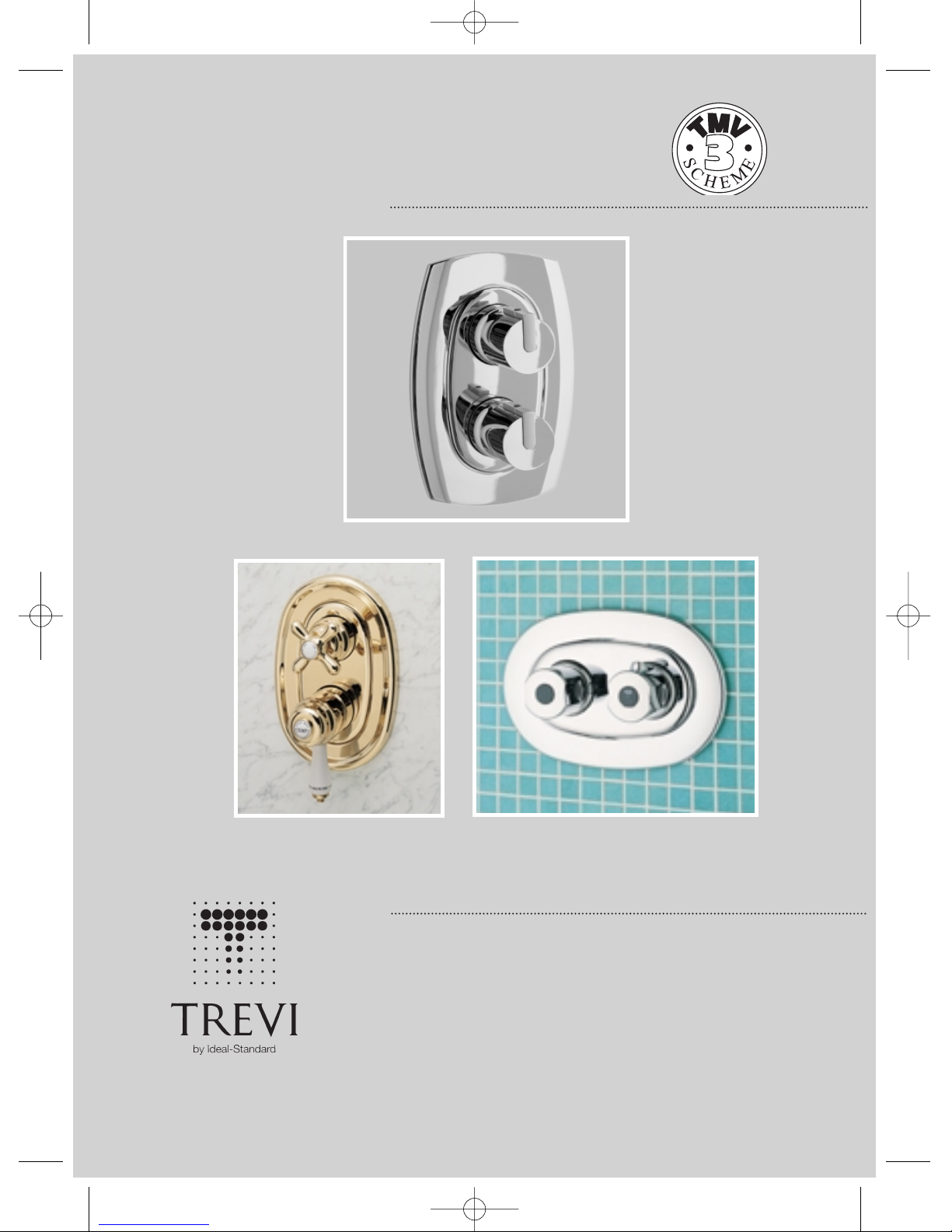
A3000 Trevi Therm built-in thermostatic mixer
A3700 Trevi Outline built-in thermostatic mixer
E3115 Trevi Traditional built-in thermostatic mixer
INSTALLER:
After installation please pass this instruction booklet to user
TREVI SHOWERS
Trevi Outline
Trevi Traditional Trevi Therm
trevi showers.qxd 04/12/03 13:21 Page 1
Page 2
WATER REGULATIONS
Hot and cold water supply pressures must be
reasonably balanced and from a common
source - both from storage or both from a
supply pipe. (IRN 101). The mixers will function
within specification on unequal pressures up to
a ratio of 5 : 1, but it is not recommended that
the cold supply be connected to the rising main
and hot to the tank fed supply as the pressure
differential is likely to exceed the 5:1 ratio.
The minimum pressure for correct operation is
0.1 bar (1m head - see Figure 5). Pressure head
is measured as the vertical distance between the
bottom of the cold water storage tank which
feeds the hot water system and the highest
point on the shower spray plate.
When installing with a shower pump the use of
a secondary tapping from the cylinder is highly
recommended.
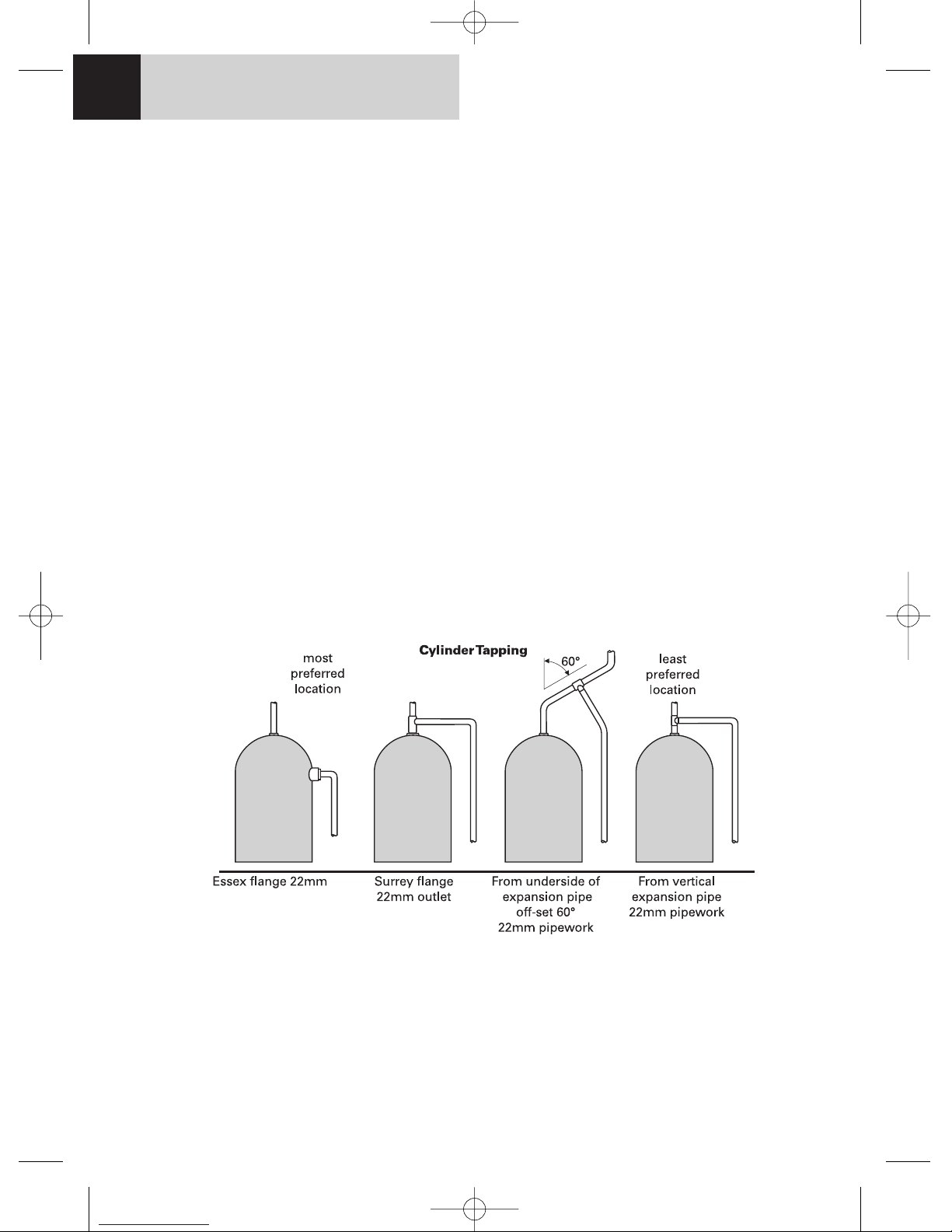
Figure 1 shows the various methods of connecting
the hot water pipe to the cylinder - the most
preferred on the left and the least preferred on
the right.
The fitting should be so installed as to be readily
accessible for examination, repair, replacement or
operation. (IRN 111).
The temperature of the hot water must not exceed
85ºC but the installer’s attention is drawn to code
of practice BS 6700 which recommends that
stored hot water should normally never exceed
65ºC. For correct operation of the valve, a
minimum of 52ºC is required.
GENERAL NOTES
Trevi thermostatic shower mixers are designed to be installed on normal UK low
pressure storage tank fed systems, unvented high pressure systems, modulating
instantaneous water heaters or modulating combination (combi) boilers. They are suitable
for all pumped applications.
Figure 1 Preferred locations of cylinder tapping
1
FOR HEALTHCARE ESTABLISHMENTS
In accordance to NHS model engineering specification DO8 the valve has approval for the following
applications: High pressure -HP-S
Low pressure -LP-S
TMV3 approval number: ETC/227/0903
trevi showers.qxd 04/12/03 13:21 Page 2
Page 3
When installing on a modulating combination
boiler it is sometimes possible for the interaction of a thermostatic valve with the combi to
cause the boiler to cut out and cut in again with
the result that the water will become alternatively cold and hot. To overcome this, flow
restrictors should be fitted upstream of the
thermostatic valve.
The Do8 approval of this fitting only
applies when installed without the flow
restrictors.
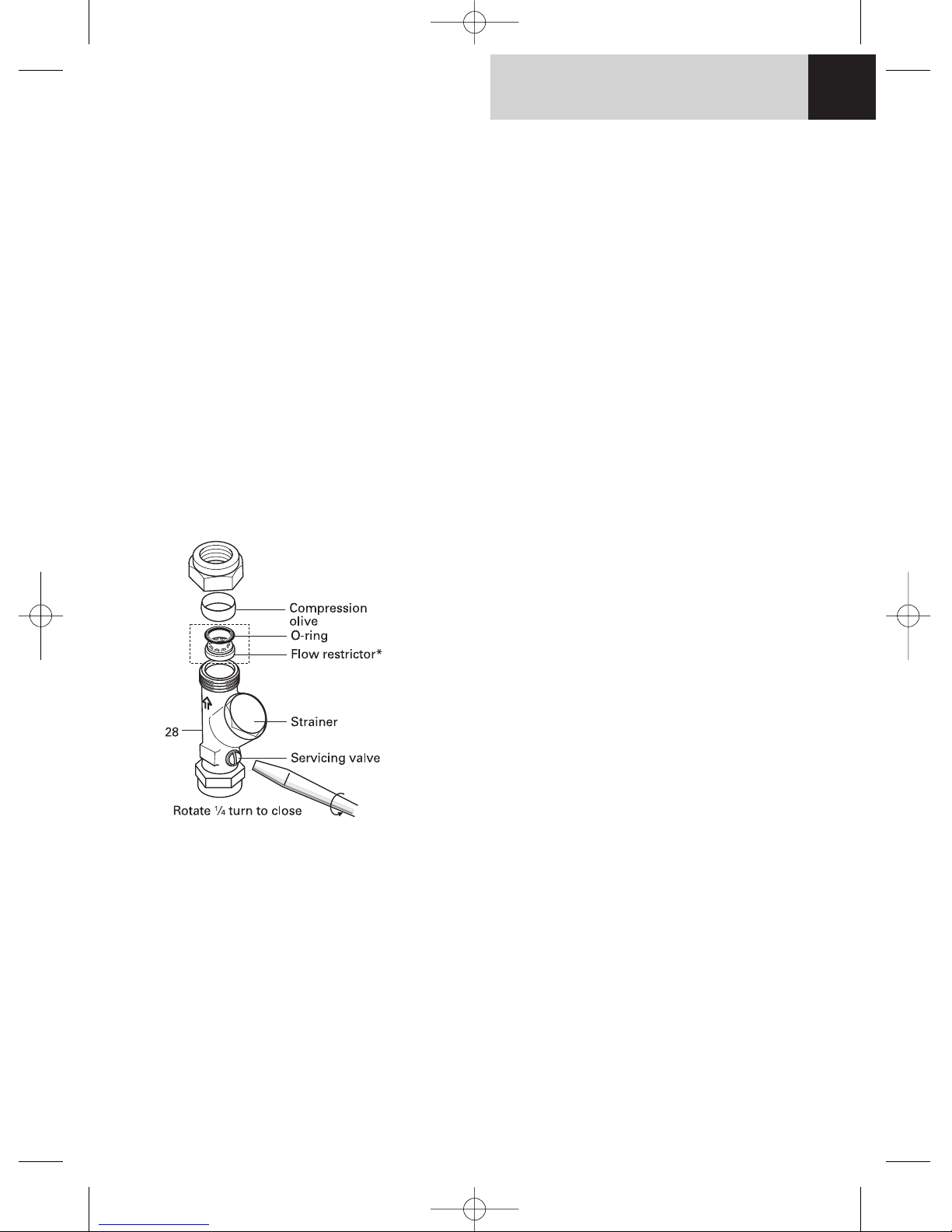
Trevi supply in-line strainers/servicing valves (28)
which include these flow restrictors. These
should be inserted in the downstream side of
the servicing valve as shown on Figure 2. It is
essential that they are positioned the right way
round as shown in the sketch. Remove the compression nut and olive from the outlet side of
the Isolating valve and place the restrictor in the
outlet. Push to the bottom of the recess. Fit Oring in the visible rebate around the edge of the
restrictor and push home until it is fully in the
rebate. Use the tip of a small screwdriver or similar to achieve this.
Servicing valves should be fitted as close as is
practical to the shower valve.
CATEGORIES OF RISK
The water regulations published in 1999* take a
new approach to backflow in that they look at
different categories of risk. The installer must
assess the risk from the various categories of
fluid in adjacent appliances before determining
the level of backflow protection required for a
particular installation. Figures 3 & 4 describe the
protection required in various installations.
CATEGORY 3 RISK
Water in a shower tray, basin or bathtub is
considered to be a fluid category 3 risk which is
a fluid which represents a slight health hazard if
it were to find it’s way back into the supply pipe.
For this reason it must not be possible for any
flexible shower head to be able to enter any adjacent washbasin, bath or shower tray unless
appropriate protection is employed. (See Figure 3).
Figure 2 in-line filter and service valve
showing restrictor
*A guide to the Water Supply (Water fittings) Regulations 1999 and the Water Byelaws 2000, Scotland is
published by WRAS (Water Regulations Advisory Scheme) Fern Close, Pen-y-Fan Industrial Estate, Oakdale, Newport, NP11 3EH.
ISBN 0-9539708-0-9.
WATER REGULATIONS 2
Table 1 Conditions for normal use
Operating pressure range: High Pressure Low Pressure
Maximum static pressure - Bar 10 10
Flow pressure hot and cold - Bar 1 to 5 0.2 to 1
Hot supply temperature - °C 52 to 65 52 to 65
Cold supply temperature - °C 5 to 20 5 to 20
Temperature differential characteristic (TDC) °C 10 10
Valves operating outside of these conditions cannot guaranteed to perform as type 3.
Approval only applies when the valves are installed without the flow restrictors
illustrated in Figure 2.
trevi showers.qxd 04/12/03 13:21 Page 3
Page 4
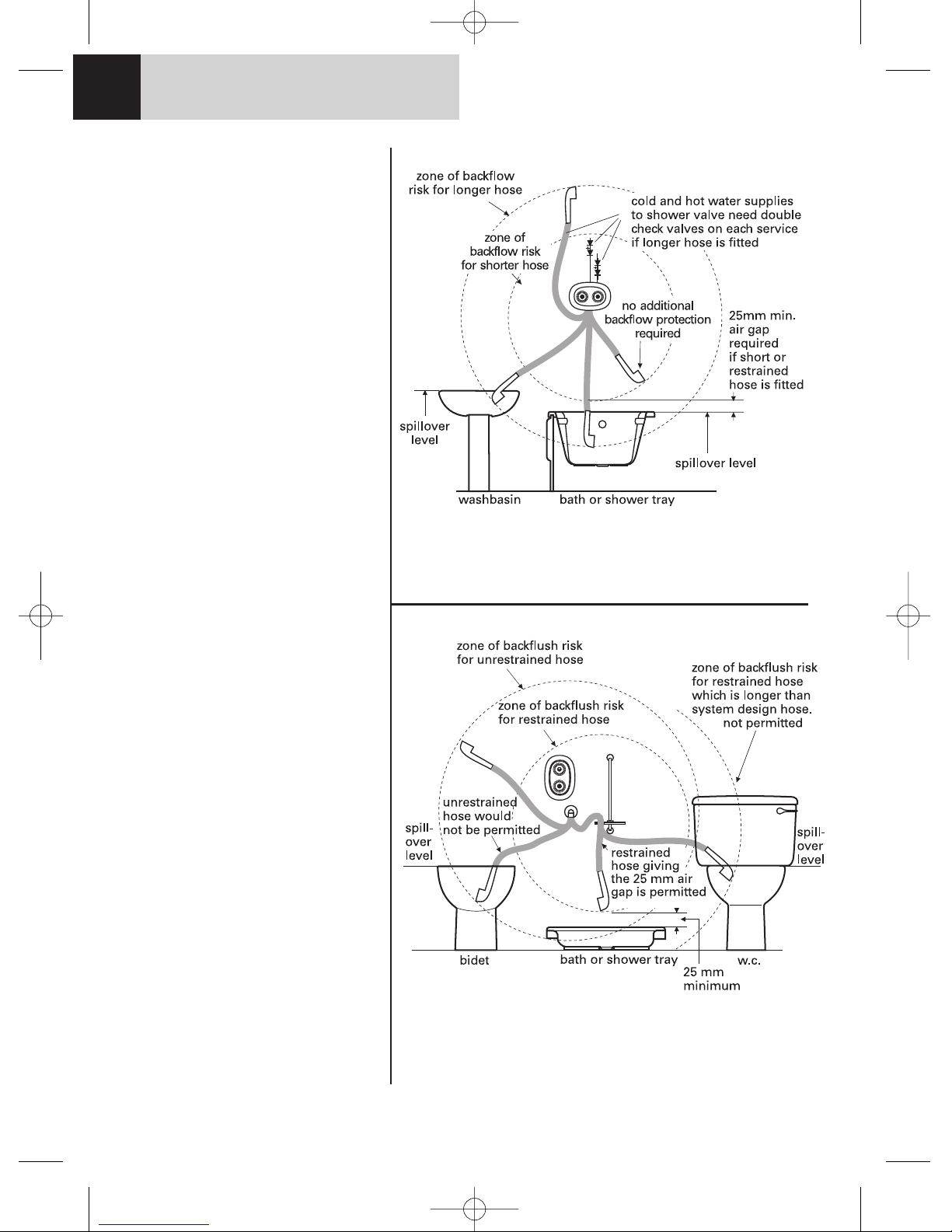
If it is desired to allow the hand spray
to be used inside say a bathtub or a
basin it is essential that double check
valves be fitted to the inlet on both
hot and cold supplies to the thermostatic valve. Alternatively single check
valves can be fitted at the inlets and
an additional check valve should be
fitted in the valve outlet.
No check valves need be fitted if
the hand spray is prevented from
reaching closer than 25mm of the
spill over level of any such fixture.
CATEGORY 5 RISK
Water in a Sink, WC or Bidet is
considered to be a fluid category 5
risk which is a fluid which represents
a serious health hazard if it were to
find it’s way back into the supply
pipe. For this reason it must not be
possible for any flexible shower head
to be able to enter any adjacent Sink,
WC or Bidet. If the flexible hose to be
fitted could reach into any such
vessel, the requirements to the
system design are so onerous it is
better not to fit a flexible. Rather, a
fixed overhead showerhead should
be considered. (See Figure 4).
It will also be seen that this risk could
change should the hose be taken out
of the restraining device or should a
longer replacement hose be fitted at
a later date. Installers and householders are advised to take account
of these factors when fitting replacement hoses.
For pumped applications the pipe
supplying the pump must not in
addition supply an ascending spray
bidet.
Figure 3 Illustration of backflow risk from fluid
Category 3 risk
WATER REGULATIONS3
Figure 4 Illustration of backflow risk from fluid
Category 5 risk
trevi showers.qxd 04/12/03 13:21 Page 4
Page 5
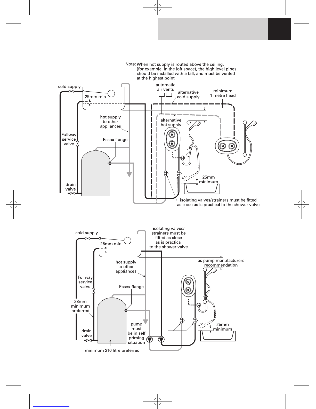
GRAVITY/PUMPED SYSTEMS
Figure 5 Recommended system layout for gravity applications
Figure 6 Recommended pumped system layout
GRAVITY & PUMPED SYSTEMS 4
trevi showers.qxd 04/12/03 13:21 Page 5
Page 6
INSTALLATION GUIDE
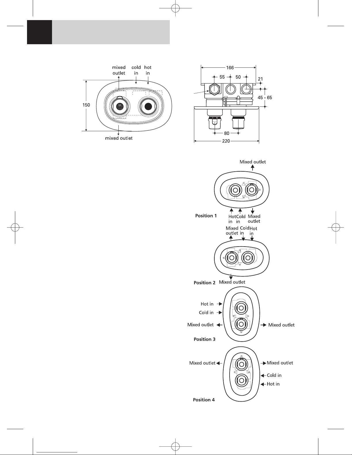
Connections on the built-in mixer body are
¾" BSP (female) and are marked “hot in”, “cold
in” and “mixed out” on the body casting. There
are two mixed outlet ports, one of which must be
plugged with the blanking plug supplied. For
maximum flow performance the unplugged outlet should be connected to the wall elbow or the
fixed overhead shower using 22mm copper. The
¾"/22mm connectors must be jointed to the valve
body using jointing compounds or PTFE tape.
Under no circumstances should soldered joints be
used near the valve body as this will damage the
fitting. It is recommended that isolation valves
be fitted upstream of the valve body.
TREVI THERM A3000
The valve is supplied as per position 1 (Figure 8)
with options for installation in positions 2, 3 & 4.
Should positions 2, 3 or 4 be required then the
temperature adjustment carrier will need to be
repositioned so that the triangular raised mark at
the rear is positioned at the top. The front handle
carrier is rotated if necessary until the triangular
indent is again at the top. The handle can then be
pushed into position with the override button to
the top.
TREVI OUTLINE THERMOSTAT A3700
This valve is supplied as per position 3. Since the
wall plate is designed to be mounted vertically,
position 4 is the only alternative orientation
advised.
TECHNICAL DIMENSIONS
Figure 7 Trevi thermostatic shower valves - installation dimensions
Figure 8
DIMENSIONS5
trevi showers.qxd 04/12/03 13:21 Page 6
Page 7
TREVI TRADITIONAL BUILT-IN E3115
Trevi Traditional is supplied as per position
3 (Figure 8) and should only be installed in this
orientation. Connections are the same as for
Trevi Therm and Trevi Outline.
Build-in guide
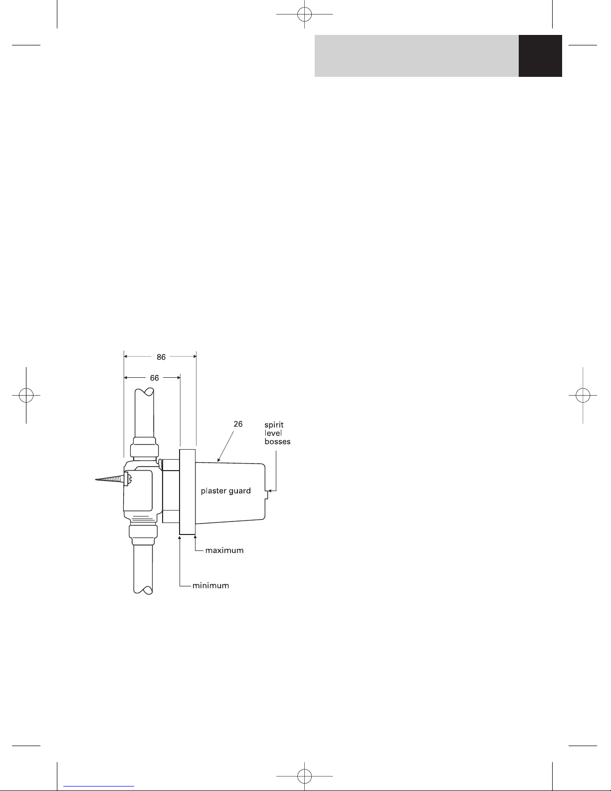
1. All the fittings covered by this instruction are
designed to be recessed into the wall. The depth
of the recess should be measured from the
finished wall surface to the rear of the valve
body. There is an adjustment of 20mm in the
installation depth. Recess depth is in the range
66mm minimum to 86mm maximum. These
minimum and maximum depths are marked on
the plaster guard (26).
2. Chase out wall for mixer body and pipe work.
3. Remove plaster guard (26).
4. Fit blanking plug to appropriate port of
the valve body and connect pipe work. (Do not
solder near the valve body)
5. Replace plaster guard and check that the
valve is horizontal (or vertical if positions 3 or 4
have been selected). The two bosses on the
front of the plaster guard allow a spirit level to
be placed on or against it. Check also that the
valve is parallel to the wall surface.
6. Make good the wall by plastering around the
valve up to the plaster guard.
7. Once the plaster has set the wall can be tiled
and the plaster guard removed.
8. The temperature control handle can now be
positioned so that the button is to the top (Trevi
Therm and Trevi Outline Thermostat). If the valve
is not being fitted in the position as supplied then
the temperature adjustment carrier will have to
be repositioned as described on Page 8 under
thermostatic cartridge replacement.
9. The pipe work and valve body must
now be flushed out. Failure to do so will
cause the thermostatic cartridge filters to
become blocked resulting in reduced or erratic
performance. The procedure for this is
described on Page 7 under replacement of
cartridges.
10. Fit the back cover plate and secure using
the fixing screws (3). (These may need to be cut
if valve is installed close to the minimum depth).
Push front cover plate into position and fit
operating handles.
Figure 9
INSTALLATION GUIDE 6
trevi showers.qxd 04/12/03 13:21 Page 7
Page 8
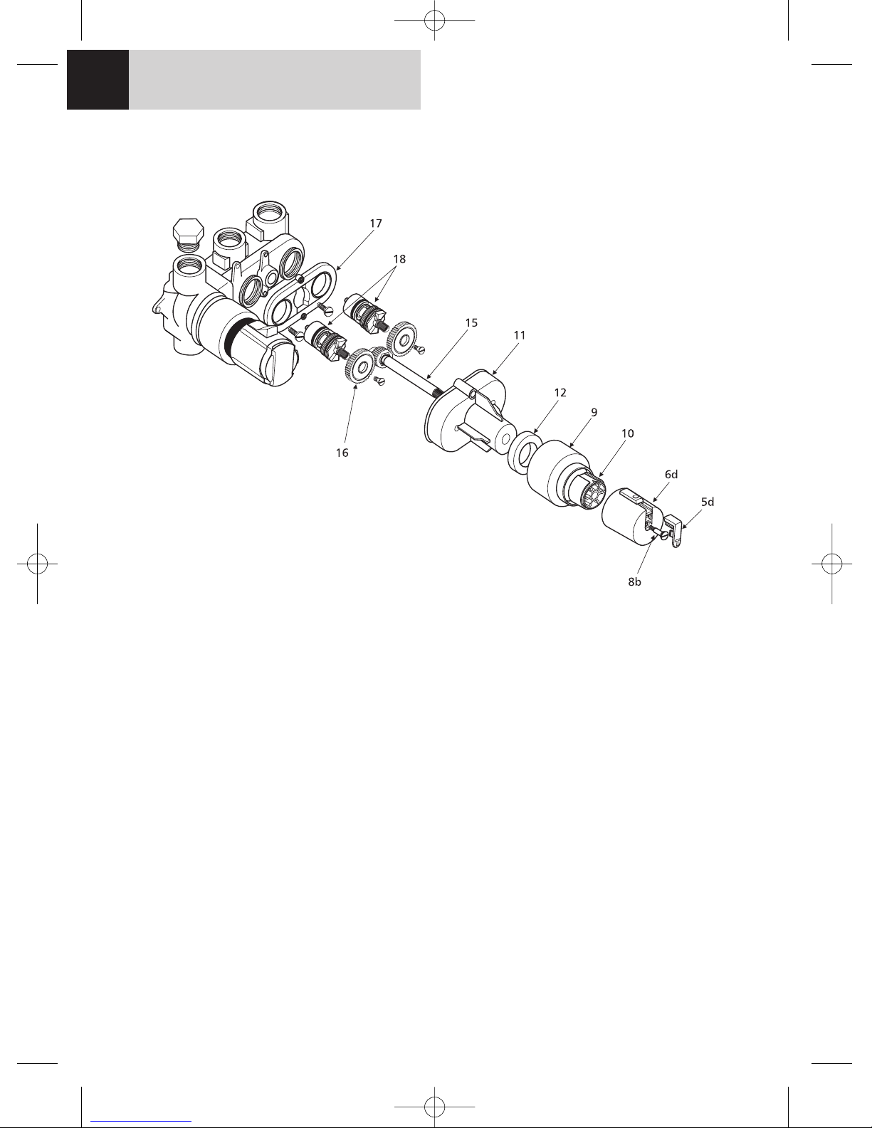
1. Remove handles. (see Pages 10/11 for details)
2. Remove the front cover plate (1) by prising
forward using the small slots at the sides of
the front cover plate.
3. Remove the two cover plate screws and pull
off the back cover plate (2).
4. Remove the volume control handle (6) and
carrier (10) by unscrewing screw (8b) and
pulling off.
5. Pull off shroud (9)
6. Remove the two gear box cover fixing
screws and pull off the gear box cover (11).
7. Pull out the drive shaft (15)
8. Loosen the two cartridge cone screws and
remove the gear/clutch wheels (16) by
pulling forward.
9. Lift off the rear gear box cover (17)
10. Isolate the shower valve from the supplies
and unscrew the two cartridges (18)
anticlockwise
11. Fit the flushing adapter (25) in place of the
cartridges in turn and flush the pipework.
12. Assemble the valve in reverse order.
13. If fitting replacement cartridges and/or
clutches they should be fitted at this stage.
14. Both cartridges must be in the closed
position before fitting the gear clutches (16)
in position.
CARTRIDGE REPLACEMENT
Flushing and replacement of cartridges & gear clutch wheels
Figure 10
VALVE REPLACEMENT7
trevi showers.qxd 04/12/03 13:21 Page 8
Page 9
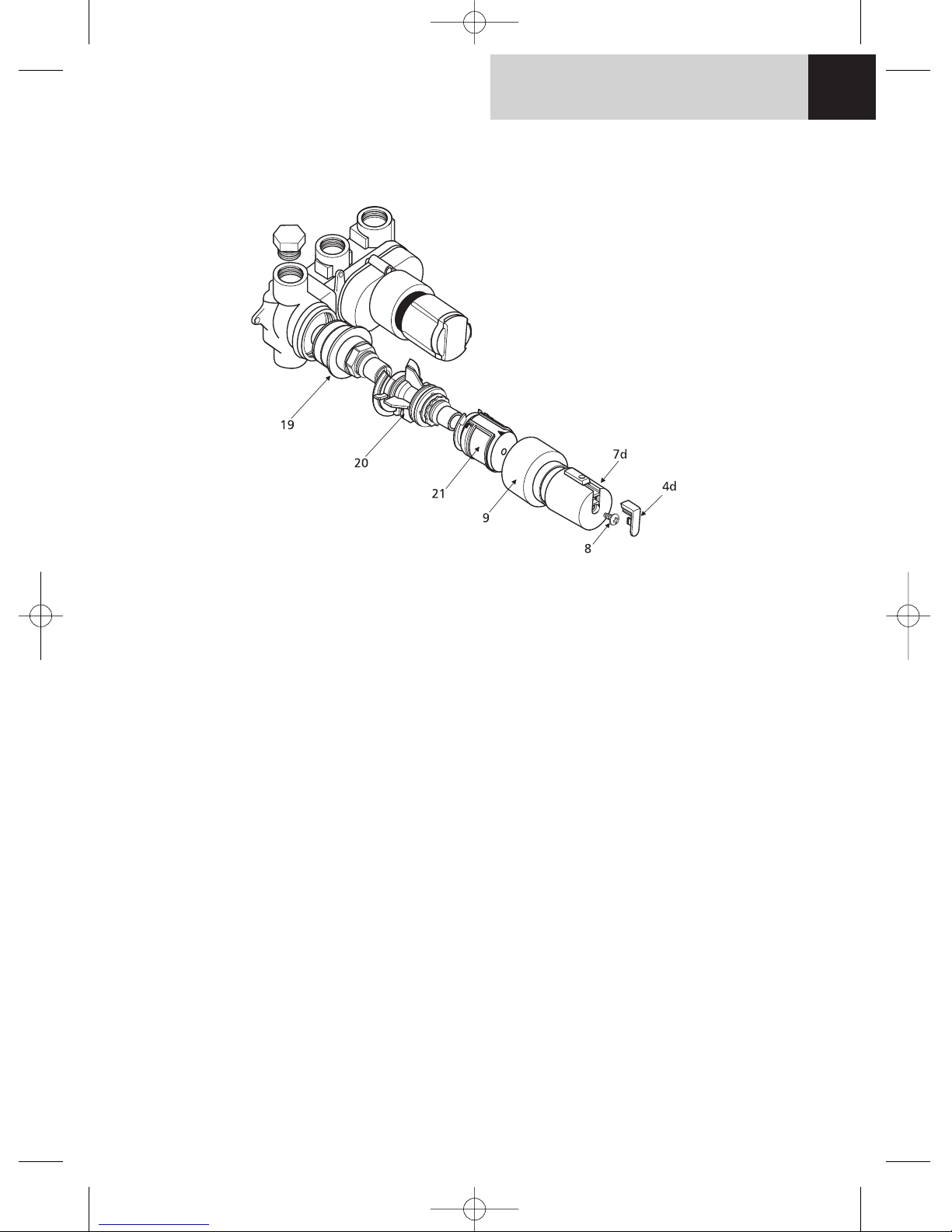
1. If the volume control handle is in the off
position it should not be necessary to isolate
the valve from the supply for this operation.
2. Remove handles (7). (see pages 10/11 for
details)
3. Remove the front cover plate (1) by prising
forward using the small slots at the sides of
the front cover plate.
4. Remove the two cover plate screws (3) and
pull off the back cover plate (2).
5. Remove shroud by pulling froward (9)
6. Remove the temperature adjustment carrier
(21) by rotating the black locking latch and
pulling forward.
7. Remove the rear temperature handle extension (20) by rotating the black locking latch
and pulling forward.
8. The thermostatic cartridge (19) can now be
removed by turning anticlockwise.
9. It is usually unnecessary to fit a new
thermostatic cartridge. Most problems
occur because debris from the pipe work
has blocked the cartridge filter screens.
10. The cylindrical filter screens can be removed
for cleaning by removing the o-rings from
the cartridge and sliding the screens off. Do
not attempt to refit the cartridge with the
filter screens missing. Any small particles of
grit in the water supply will cause the mechanism to jam. (Place all components which
have grease on them on a clean piece of
paper to avoid picking up grit)
11. Grease the cartridge o-rings with silicone
grease when they have been refitted.
12. If a replacement cartridge is being fitted, fit
it at this stage.
13. The valve is assembled in reverse order.
THERMOSTATIC CARTRIDGE REPLACEMENT
Figure 11
THERMOSTAT REPLACEMENT 8
trevi showers.qxd 04/12/03 13:21 Page 9
Page 10
Details of the recommended code of
practice for safe water temperatures can
be found on the Thermostatic Mixing
Valve Manufactures Association web site:
www.tmva.org.uk
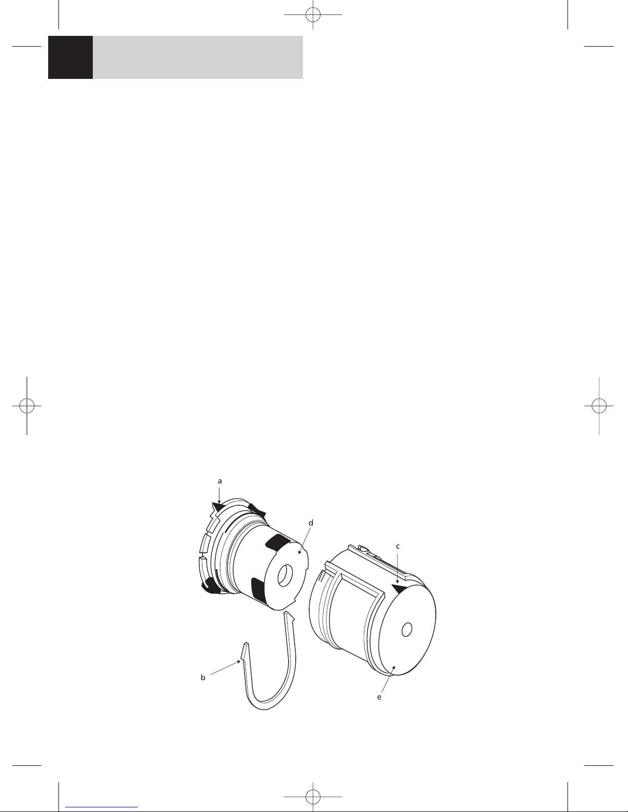
The rear temperature handle extension (20) can
be fitted on to the thermostatic cartridge (19) in
any position.
The temperature adjustment carrier (21) will
need to be refitted with the triangular raised
mark on the rear of the carrier in the top position. Providing this assembly has not been separated, (i.e. the red clip removed) the unit will
remain calibrated and no adjustments will be
required. Ensure that the front handle carrier is
rotated fully anticlockwise before refitting
otherwise difficulty will be experienced in fitting
the temperature adjustment carrier to the rear
temperature extension. The temperature handle
is then refitted with the override button again in
the top position.
CALIBRATION
Trevi thermostats are factory calibrated and
require no further calibartion during installation. However, if the temperature adjustment
carrier is accidentally disturbed and the calibration altered it is a simple procedure to recalibrate the unit. Before starting this you will need
to ensure the hot supply temperature is above
52ºC.
1. Remove the temperature control handle.
2. Remove the red U-clip (b) from the temperature adjustment carrier. Remove the front
carrier (e).
3. Ensure the raised triangular mark (a) on the
rear handle carrier is to the top.
4. Rotate the temperature adjusting spindle
(d) until a temperature of 40ºC is measured
at the outlet.
5. Replace the front handle carrier ensuring
the triangular indent (c) is to the top.
6. Refit the red U-clip.
7. Refit the temperature handle.
Figure 12
CALIBRATION9
trevi showers.qxd 04/12/03 13:21 Page 10
Page 11

1. Repeat the procedure of recording and checking supply temperatures. (The same type of
measuring equipment should be used).
2. If the temperature has the changed significantly from the previously recorded valves,
check the following :
a) All inline or integral valve filters are
clear of obstruction.
b) All inline or integral check valves are
clean and working properly to prevent
backflow.
c) Any isolating valves are fully open.
3. When satisfied with the mixed outlet temperatures re-record the temperatures. If the
change in temperature of the mixed water is
extreme it is advisable to increase the
frequency of servicing, unless temperature
stability is achieved.
MAINTENANCE 10
The thermostatic cartridge seldom fails and the possibility of blocked filters should be investigated
before contemplating replacing it.
Although the Trevi Therm is supplied with strainers in the separate servicing valves, small particles of
debris may find their way past this and onto the filter screens in the thermostatic cartridge. These
should be cleaned and refitted. See section on cartridge replacement.
This shower valve has safety characteristics superior to the previous version of the Trevi Therm and is
approved to TMV3 standard, which allows it to be used in hospitals, nursing homes and residential
care home. When installed in such establishments it is a requirement that the following commissioning and maintenance procedures be carried out. For normal domestic installations these checks
are not a requirement.
The following procedures should be carried out
after installation and every 6 months after to
ensure that the valve is functioning correctly.
Check that:
1. The application of the thermostatic valve
matches the approved designation.
2. The supply pressures are within the recommended range for the application.
3. The supply temperatures are within the permitted range for the application and comply
with the guidance for prevention of
Legionella.
4. The mixed temperature is as required for the
application.
Record:
5. Each hot and cold supply. (Make a note of
the measuring device used).
6. The mixed water temperature at the outlet
device.
Isolate:
7. The cold supply to the mixing valve and
record the mixed water temperature. The
temperature should not exceed the value
given in table (1) below.
COMMISSIONING & PERIODIC CHECKS
FREQUENCY OF REGULAR SERVICING
The purpose of servicing regularly is to monitor the performance of changes in system and valve set
up. This may require the need to adjust either the supply system or the valve. The A3000, A3700 or
E3115 should be checked and tested 6 to 8 weeks and again 12 to 15 weeks after commissioning.
The results are to be compared against original commissioning settings. If there is no significant
change (i.e. less than 1K) then a 6 monthly servicing cycle may be adopted. If the temperature
increases up to and greater than 2K at the mixed water outlet, then servicing checks should be carried out more frequently, (every 4 months).
The following procedure is recommended for all servicing:
TABLE (1)
A guide to maximum temperature sets
Application Mixed Water Permitted maximum temperature rise
temperature during site testing
Shower 41 °C 43 °C
trevi showers.qxd 04/12/03 13:21 Page 11
Page 12
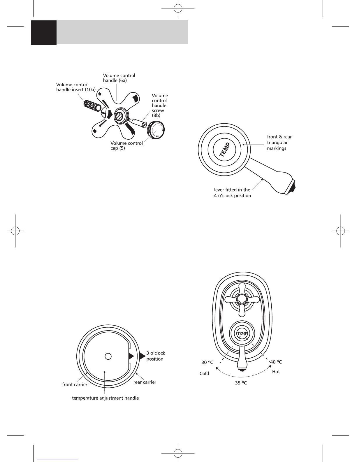
Trevi Traditional
The volume and temperature control handles
are not pre-fitted but are supplied packed
with the valve.
The Traditional valve should be fitted only in
position 3 as shown as in Figure 8
1. Push the volume control handle insert (10a)
into the volume control handle (6a) and
push this assembly on the drive shaft (15).
2 Secure with the screw (8b) and finally push
the cap (5) into place
For correct operation the temperature handle
must be fitted as follows
1 The temperature adjustment carrier is fitted
as below.
2. To fit the temperature handle (7a), push it
onto the temperature adjustment carrier
(21) with the lever at the 4 o’clock position.
The wide key on the inside of the lever
should engage with the key way on the
temperature adjustment carrier (21).
3. Secure the lever with the screw (8)
4. When the lever is moved to the 6 o’clock
position the water temperature should be
approximately 35ºC
5. To increase the temperature, move the
handle anticlockwise. See Figure 16
Figure 14
Figure 15
Figure 16
HANDLE FIXATION/REMOVAL
11
Figure 13 Fitting Trevi Traditional
volume control handle
trevi showers.qxd 04/12/03 13:21 Page 12
Page 13
Trevi Therm and Trevi Outline
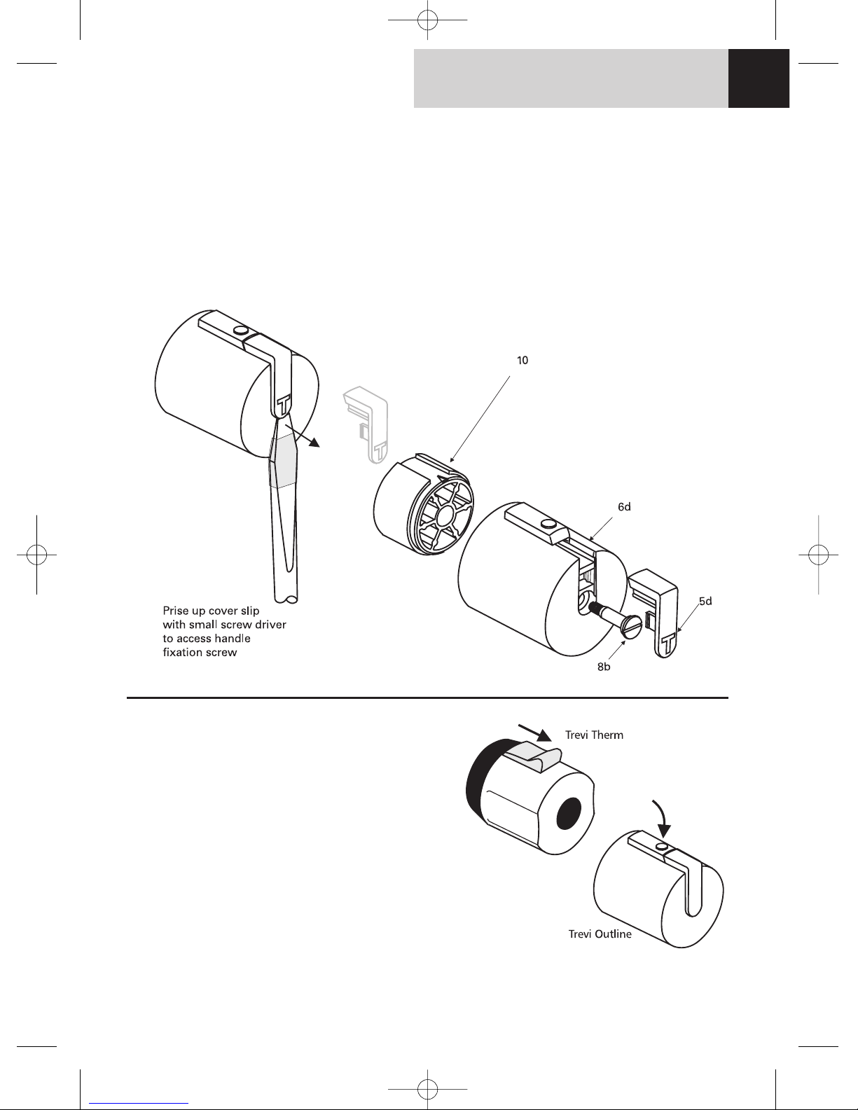
To remove the Outline handles, the cover slip
(4d or 5d) should be prised up by inserting a
small screw driver in the recess as shown. Care
should be taken not to scratch the handle while
doing this and it is advisable to wrap a piece of
masking tape or similar around the screw driver
as shown.
Unscrew screw (8b) and slide the handle off.
The handle carrier can then be removed.
To replace the handle slide onto handle carrier
(10) ensuring the key inside the handle engages
with the keyway in the carrier (10).
HANDLE FIXATION/REMOVAL 12
Figure 17
Temperature over-ride button
The Trevi Therm and the Trevi Outline
Thermostat (but not the Trevi Traditional) are
fitted with a temperature over-ride button.
Normally this is pre-set to limit the temperature
to 40ºC. However, higher temperatures may
be obtained by pressing the button and rotating the temperature handle further.
The Trevi Therm button slides outwards and the
Trevi Outline Thermostat button pivots inwards
as shown.
trevi showers.qxd 04/12/03 13:21 Page 13
Page 14
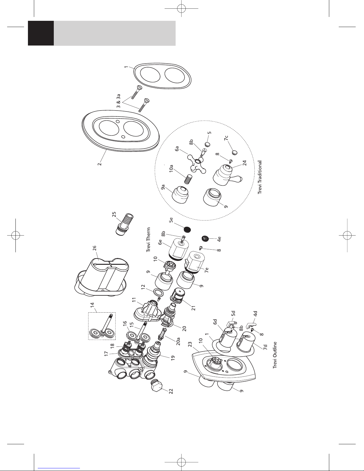
Figure 19
SPARE PARTS
13
trevi showers.qxd 04/12/03 13:21 Page 14
Page 15

Ref. Description
1 Front cover plate
2 Wall plate for Trevi Therm & Traditional
2a Cover plate sealing rings
3 Cover plate fixing screws 50 mm
3a Cover plate fixing screws 60 mm
4d Outline temperature handle cover slip
4e Trevi Therm Temperature handle cap
5 Traditional volume control handle cap
5d Outline volume handle cover slip
5e Trevi Therm volume handle cap
6a Traditional volume handle
6d Outline volume handle
6e Trevi Therm volume handle
7c Traditional temperature handle index
7d Outline temperature handle
7e Trevi Therm Temperature handle
8 Self tapping handle screw
8b Long volume handle screw
9 Standard Shroud
9a Traditional Volume control handle shroud
Ref. Description
10 Volume control handle carrier
10a Traditional volume control handle insert
11 Gear box cover
12 Gear box sealing washer
13 Gear box cover fixing screws
14 Gear/clutch wheels complete
15 Gear/ wheel drive shaft
16 Gear/clutch wheels
17 Gear box back plate
18 1/2” cartridge
19 Thermostatic control cartridge
20 Temperature handle extension
21 Temperature adjustment carrier complete
22 Blanking plug
23 Outline wall plate
24 Traditional temperature handle
25 Flushing adapter outlet
26 Mounting template/plaster guide
27 Mounting template/plaster guide screws
SPARE PARTS 14
trevi showers.qxd 04/12/03 13:21 Page 15
Page 16

Trevi Showers pursue a policy of continuing
improvement in design and performance of its
products.
The right is, therefore, reserved to vary
specifications without notice.
Trevi Showers is a division of
American Standard Plumbing (UK) Ltd. T 096 09/03
Trevi Showers.
The Bathroom Works,
National Avenue,
Kingston upon Hull,
HU5 4HS
England.
Telephone: 01482 470788
Fax: 01482 445886
CUSTOMER CARE HELPLINE
0870 1296086
FAX LINE 01482 499611
email: [email protected]
E965033
trevi showers.qxd 04/12/03 13:21 Page 16
 Loading...