

Treston US-10049562P, US-10049561P, US-10049560P, US-10049565P, US-10049564P User Manual
...
WATCH THE VIDEO
INSTRUCTIONS HERE!
ASSEMBLY INSTRUCTIONS
Concept Manual
900020
2014-03-10
1 (6)
Treston • 156 Bluffs Court, Canton, GA 30114
Tel. 800.437.6772 • Fax 770.720.6584 • infousa@treston.com • www.treston.us
ASSEMBLY INSTRUCTIONS
ASSEMBLY INSTRUCTION
905990
2018-01-08
2 (14)
Concept Manual
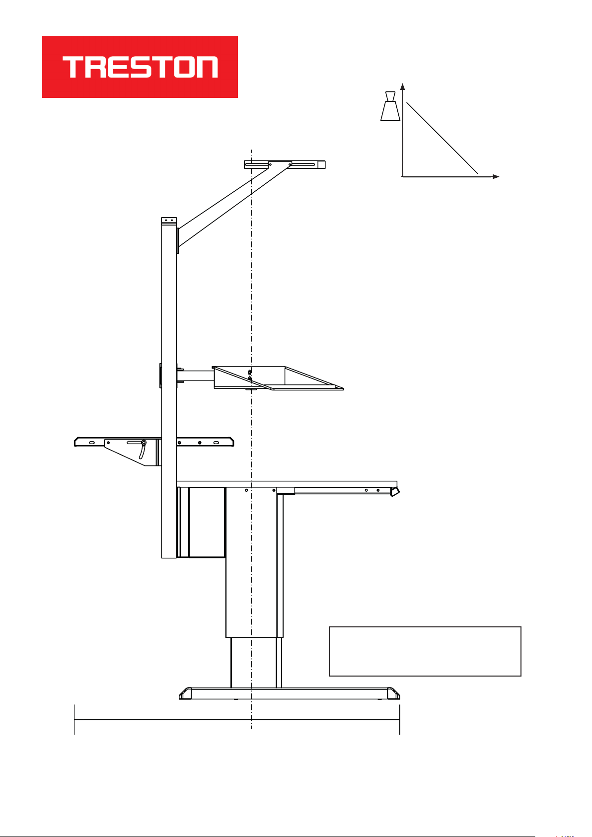
kg
2014-03-10
0.75 m
900020
2 (6)
0.75 m
NOTE: Foot tubes can be mounted
to legs in two optional positions,
depending on load requirements.
0.75 m
Treston • 156 Bluffs Court, Canton, GA 30114
Tel. 800.437.6772 • Fax 770.720.6584 • infousa@treston.com • www.treston.us

TOOLS REQUIRED FOR INSTALLATION:
• 13mm wrench
• 19mm wrench
• Phillips head screwdriver
• 5mm hex key
Optional:
• Drill with bits for faster installation and predrilling holes for worksurface
ASSEMBLY INSTRUCTIONS
Concept Manual
900020
2014-03-10
3 (6)
• 100% silicone for worksurface assembly
HARDWARE INCLUDED:
• (4) foot glides
• (4) plastic hole plugs
• (2) M8 x 100 bolts
• (2) M8 tab inserts
• (7) wood screws
• (10) M8 X 16 bolts
• (4) upright mounting tabs
Treston • 156 Bluffs Court, Canton, GA 30114
Tel. 800.437.6772 • Fax 770.720.6584 • infousa@treston.com • www.treston.us

ASSEMBLY INSTRUCTIONS
Concept Manual
900020
2014-03-10
4 (6)
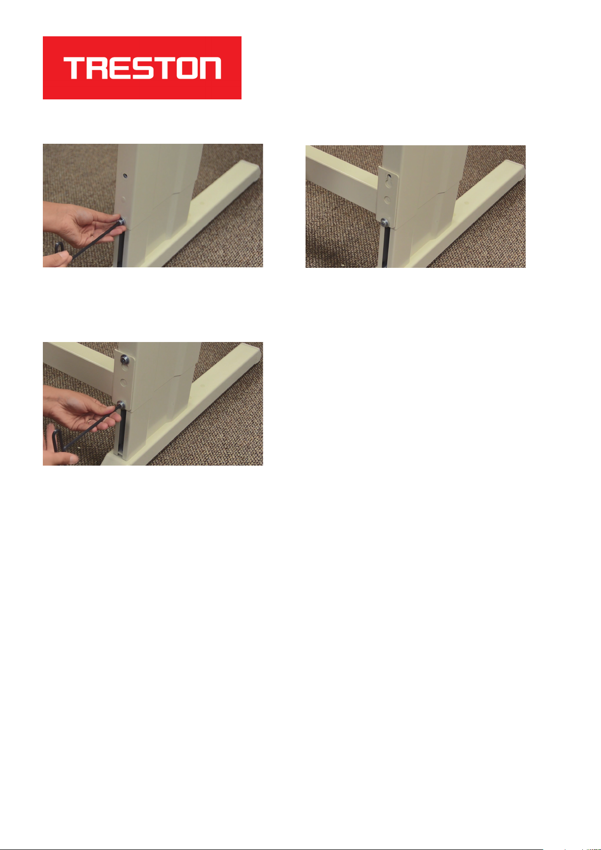
STEP 1: Loosen bolts on inside and back of table frame
legs.
STEP 3: Tighten bolts to 27 Nm. Using a torque wrench
will ensure table is properly tightened to prevent slippage.
STEP 2: Adjust leg height to desired position.
STEP 4: Attach foot glides to bottom of foot tubes using
a Phillips head screwdriver, then tighten with a 19mm
wrench.
STEP 5: Locate slotted hole on rear case and attach to
table legs with M8 x 16 bolts, so that the slotted hole will
be positioned under worksurface.
Tel. 800.437.6772 • Fax 770.720.6584 • infousa@treston.com • www.treston.us
STEP 6: Tighten bolts.
Treston • 156 Bluffs Court, Canton, GA 30114

ASSEMBLY INSTRUCTIONS
Concept Manual
900020
2014-03-10
5 (6)
STEP 7: Insert metal tabs into front rail.
STEP 9: Using the same attachment method as the front
rail, mount the back rail/drawer support rail to the legs.
Tighten bolts.
STEP 8: Attach front rail to table legs using M8 x 100
bolts. Tighten bolts. Note: There are three available
positions for mounting front rail. If drawers will be
mounted, select the front rail position suitable for depth of
drawer.
STEP 10: Insert hole plugs into table feet for a clean
finish.
STEP 11: Mount worksurface to frame, using one of the
attachment methods suggested to the right.
Tel. 800.437.6772 • Fax 770.720.6584 • infousa@treston.com • www.treston.us
WORKSURFACE ATTACHMENT OPTIONS:
LAMINATE TOPS
Use wood screws provided
PHENOLIC TOPS
Pre-drill holes and use wood screws provided
OR
Use 100% silicon adhesive
Treston • 156 Bluffs Court, Canton, GA 30114
ASSEMBLY INSTRUCTIONS
Concept Manual
900020
2014-03-10
6 (6)
STEP 12: To attach accessory/support bar, remove top
bolt from back of each leg, and loosen the lower bolt (do
not remove).
STEP 14: Reinsert removed bolt and retighten bolts to 27
Nm.
STEP 13: Attach accessory/support bar by sliding bar
over bottom bolt.
Treston • 156 Bluffs Court, Canton, GA 30114
Tel. 800.437.6772 • Fax 770.720.6584 • infousa@treston.com • www.treston.us
 Loading...