

Treston 14-C12049206, 14-C12041204, 14-C12049205, 14-C12049204, 14-C12041205 User Manual
...
ASSEMBLY INSTRUCTIONS
Cornerstone Bench
905998
10/17/19
1 (7)
Treston • 156 Bluffs Court, Canton, GA 30114
Tel. 800.437.6772 • Fax 770.720.6584 • infousa@treston.com • www.treston.us
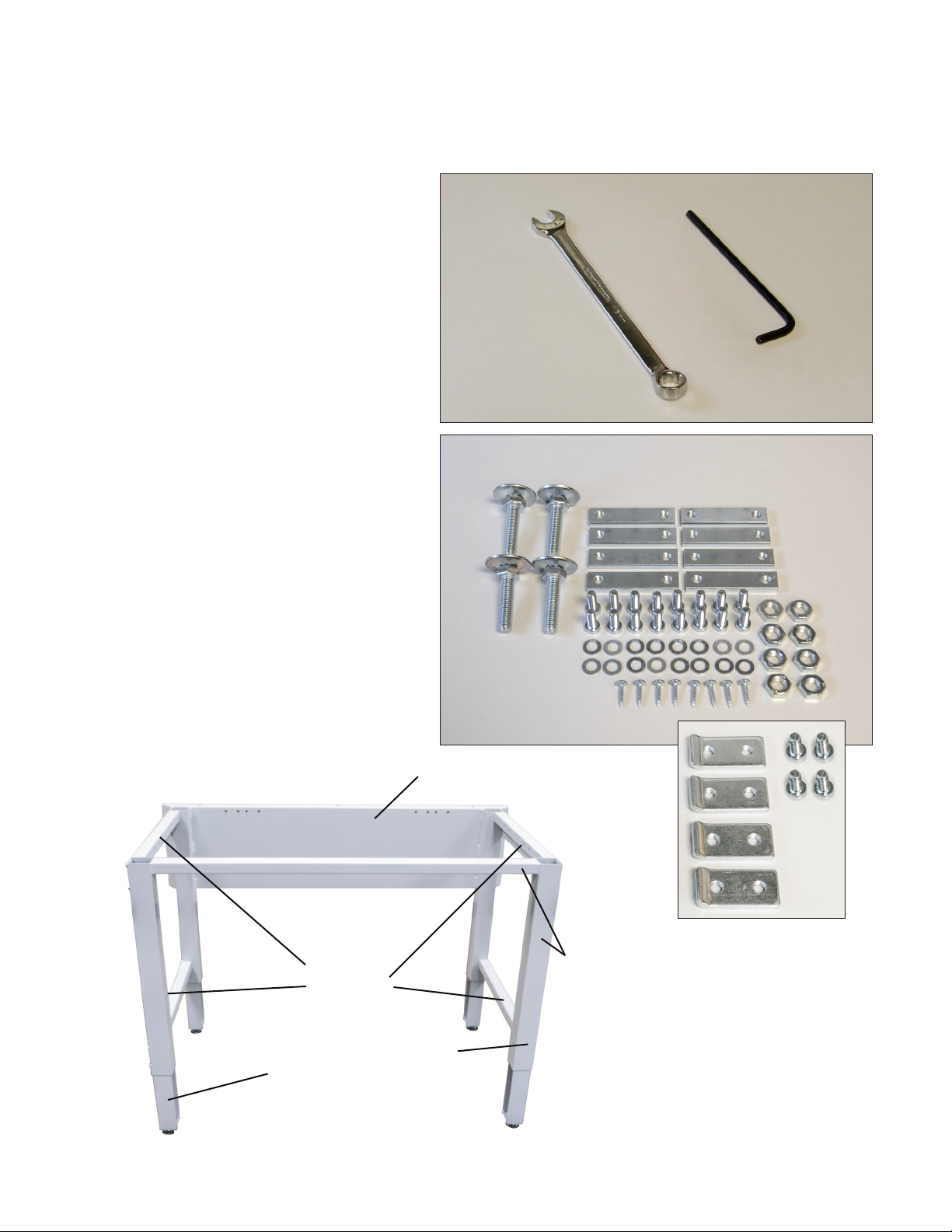
TOOLS REQUIRED FOR INSTALLATION:
• 5mm hex key
• 19mm wrench
HARDWARE INCLUDED:
• (4) 12mm foot glides
• (8) threaded nut plates
• (16) M8 x 20 bolts
• (16) M8 washers
• (8) 12mm nuts
• (8) wood screws
ASSEMBLY INSTRUCTIONS
Cornerstone Bench
905998
10/17/19
2 (7)
Hardware for optional upright attachment:
• (4) upright tabs
• (4) M8 x 16 bolts
depth kit
rails
telescoping legs
rear case assembly
front leg assembly
leg tubes
Treston • 156 Bluffs Court, Canton, GA 30114
Tel. 800.437.6772 • Fax 770.720.6584 • infousa@treston.com • www.treston.us
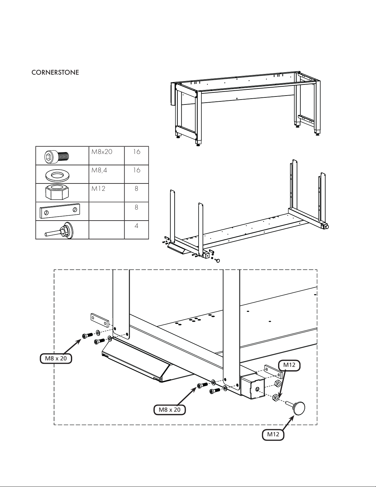
CORNERSTONE
M8x20 16
M8,4 16
M12 8
8
4
M8 x 20
M12
M12
M8 x 20
ASSEMBLY INSTRUCTION
905998
2019-11-07
1 (3)
ASSEMBLY INSTRUCTIONS
Cornerstone Bench
905998
10/17/19
3 (7)
Tel. 800.437.6772 • Fax 770.720.6584 • infousa@treston.com • www.treston.us
Treston • 156 Bluffs Court, Canton, GA 30114

ASSEMBLY INSTRUCTIONS
M8 x 20
M8 x 20
M12
M12
ASSEMBLY INSTRUCTION
905998
2019-11-07
2 (3)
Cornerstone Bench
905998
10/17/19
4 (7)
Treston • 156 Bluffs Court, Canton, GA 30114
Tel. 800.437.6772 • Fax 770.720.6584 • infousa@treston.com • www.treston.us

ASSEMBLY INSTRUCTIONS
4,5 x 20
4,5x20 8
ASSEMBLY INSTRUCTION
905998
2019-11-07
3 (3)
Cornerstone Bench
905998
10/17/19
5 (7)
LAMINATE
Treston laminate tops assembled with wood screws provided.
PHENOLIC
DO NOT USE provided screws from the hardware pack provided with the table. These screws are for
laimate work surfaces only.
Treston phenolic tops can be assembled in 2 ways:
• Mechanical fasteners - Screws to be provided by the installer. Pre-drill a pilot hole in the bottom of the work
surface, taking care to keep from penetrating through the top. The pre-drilled hole should be the same length as
the screw shaft. The screw should be slightly larger in diameter than the pilot hole. Use a coarse threaded screw,
wood or machine.
• Adhesive - Provided by the installer. Use 100% silicon. Apply several “spots” or a continuous bead to the top of
the table frame. Position the work surface as centered on the frame and let cure for 12 hrs at room temp.
Treston • 156 Bluffs Court, Canton, GA 30114
Tel. 800.437.6772 • Fax 770.720.6584 • infousa@treston.com • www.treston.us

work surface
support lip
ASSEMBLY INSTRUCTIONS
Cornerstone Bench
905998
10/17/19
6 (7)
STEP ONE: Lay rear case assembly with back side
down. Attach depth kit rails to the legs with the work
surface support lips facing up, flush with the inside of the
leg. Attach the depth kit rail using M8 hardware, inserting
threaded nut plate into legs.
NOTE: Wait to attach lower depth kit rails until step 3,
after telescoping legs have been inserted.
STEP THREE: Attach lower depth kit rails to legs
using M8 hardware. Insert the threaded nut plate into
telescoping leg. M8 bolts with washers will hold depth kit
rail, leg tube and telescoping leg together.
STEP TWO: Insert telescoping legs into leg tubes. Align
holes with outer side of the leg tubes. Set to desired
position/height of the table.
STEP FOUR: With rear case still laying flat on the floor,
lay front leg and front rail assembly onto depth kit rails,
keeping the depth kit rails flush with the outsides of the
front assembly.
STEP FIVE: Attach front leg/front rail assembly to the
rest of the frame with M8 hardware and nut plates. Insert
telescoping legs into leg tubes before attaching lower
depth kit rails. (see steps 1-3). Tighten all bolts.
NOTE: If adding a bottom shelf, depth kit rails should be
mounted with lip facing out to support shelf brackets.
Tel. 800.437.6772 • Fax 770.720.6584 • infousa@treston.com • www.treston.us
STEP SIX: Floor glides will each require 2 nuts for
mounting. Before attaching floor glides to legs, place first
nut on bolt in desired location.
Treston • 156 Bluffs Court, Canton, GA 30114

ASSEMBLY INSTRUCTIONS
Cornerstone Bench
905998
10/17/19
7 (7)
STEP SEVEN: Insert glide into bottom of telescoping leg
tubes. Attach second nut to glide stem and tighten. (In the
above photo, the glide is placed in the shortest position.)
STEP NINE: Attach laminate work surface using
provided hardware. For phenolic tops, please refer to
work surface instructions, right.
STEP EIGHT: Rotate table into upright position.
LAMINATE
Treston laminate tops assembled with wood screws
provided.
PHENOLIC
DO NOT USE provided screws from the hardware
pack provided with the table. These screws are for
laimate work surfaces only.
Treston phenolic tops can be assembled in 2 ways:
• Mechanical fasteners - Screws to be provided by the
installer. Pre-drill a pilot hole in the bottom of the work
surface, taking care to keep from penetrating through
the top. The pre-drilled hole should be the same length
as the screw shaft. The screw should be slightly larger
in diameter than the pilot hole. Use a coarse threaded
screw, wood or machine.
• Adhesive - Provided by the installer. Use 100% silicon.
Apply several “spots” or a continuous bead to the top of
the table frame. Position the work surface as centered on
the frame and let cure for 12 hrs at room temp.
Treston • 156 Bluffs Court, Canton, GA 30114
Tel. 800.437.6772 • Fax 770.720.6584 • infousa@treston.com • www.treston.us
 Loading...