

Page 1

BXT7059 / BXTS7059
7059-xxx
No. 87-0067062-000 Revision A
BIOS SETUP
TECHNICAL REFERENCE
Aptio® 4.x Test Setup Environment (TSE)
For use with BXT7059 or BXTS7059
Intel® Xeon® E5-2400 Series
8, 6 and 4-Core
PROCESSOR-BASED
SHB
Page 2

WARRANTY
The following is an abbreviated version of Trenton Systems’ warranty policy for PICMG
For a complete warranty statement, contact Trenton or visit our website at www.TrentonSystems.com.
®
Trenton PICMG
1.3 products are warranted against material and manufacturing defects for five years from
date of delivery to the original purchaser. Buyer agrees that if this product proves defective Trenton
Systems, Inc. is only obligated to repair, replace or refund the purchase price of this product at the
discretion of Trenton Systems. The warranty is void if the product has been subjected to alteration, neglect,
misuse or abuse; if any repairs have been attempted by anyone other than Trenton Systems, Inc.; or if
failure is caused by accident, acts of God, or other causes beyond the control of Trenton Systems, Inc.
Trenton Systems, Inc. reserves the right to make changes or improvements in any product without incurring
any obligation to similarly alter products previously purchased.
In no event shall Trenton Systems, Inc. be liable for any defect in hardware or software or loss or
inadequacy of data of any kind, or for any direct, indirect, incidental or consequential damages arising out
of or in connection with the performance or use of the product or information provided. Trenton Systems,
Inc.’s liability shall in no event exceed the purchase price of the product purchased hereunder. The
foregoing limitation of liability shall be equally applicable to any service provided by Trenton Systems,
Inc.
ETURN POLICY
R
A Return Material Authorization (RMA) number, obtained from Trenton Systems prior to return, must
accompany products returned for repair. The customer must prepay freight on all returned items, and the
customer is responsible for any loss or damage caused by common carrier in transit. Items will be returned
from Trenton Systems via Ground, unless prior arrangements are made by the customer for an alternative
shipping method
To obtain an RMA number, call us at (800) 875-6031 or (770) 287-3100. We will need the following
information:
Return company address and contact
Model name and model # from the label on the back of the product
Serial number from the label on the back of the product
Description of the failure
An RMA number will be issued. Mark the RMA number clearly on the outside of each box, include a
failure report for each board and return the product(s) to our Utica, NY facility:
TRENTON Technology Inc.
1001 Broad Street
Utica, NY 13501
Attn: Repair Department
Contact Trenton for our complete service and repair policy.
®
1.3 products.
Page 3

TRADEMARKS
IBM, PC/AT, VGA, EGA, OS/2 and PS/2 are trademarks or registered trademarks
of International Business Machines Corp.
AMI, Aptio and AMIBIOS are trademarks of American Megatrends Inc.
Intel, Xeon, Intel Quick Path Interconnect, Intel Hyper-Threading Technology and Intel Virtualization
Technology are trademarks or registered trademarks of Intel Corporation.
MS-DOS and Microsoft are registered trademarks of Microsoft Corp.
PICMG, SHB Express and the PICMG logo are trademarks or registered trademarks
of the PCI Industrial Computer Manufacturers Group.
PCI Express is a trademark of the PCI-SIG
All other brand and product names may be trademarks or registered trademarks
of their respective companies.
L
IABILITY DISCLAIMER
This manual is as complete and factual as possible at the time of printing; however, the information in this
manual may have been updated since that time. Trenton Systems Inc. reserves the right to change the
functions, features or specifications of their products at any time, without notice.
Copyright
© 2012 by Trenton Systems, Inc. All rights reserved.
E-mail:
Web: www.TrentonSystems.com
TRENTON Systems Inc.
2350 Centennial Drive • Gainesville, Georgia 30504
Sales: (800) 875-6031 • Phone: (770) 287-3100 • Fax: (770) 287-3150
Page 4

This page intentionally left blank
Page 5

Table of Contents
CHAPTER 1 STARTING APTIO® TSE................................................................................................ 1-1
Introduction.......................................................................................................................................................1-1
Starting Aptio TSE............................................................................................................................................ 1-1
Press DEL or F2 to enter Setup....................................................................................................................... 1-1
Aptio® TSE Setup Menu ..................................................................................................................................1-2
Navigation ......................................................................................................................................................... 1-2
CHAPTER 2 ADVANCED SETUP........................................................................................................ 2-1
Introduction.......................................................................................................................................................2-1
PCI Sub-System Settings................................................................................................................................. 2-1
ACPI Settings.................................................................................................................................................... 2-3
Trusted Computing Settings ........................................................................................................................... 2-3
WHEA Configuration ........................................................................................................................................2-3
CPU Configuration............................................................................................................................................ 2-3
Runtime Error Logging Configuration ............................................................................................................ 2-4
SATA Configuration ......................................................................................................................................... 2-4
SAS Configuration............................................................................................................................................2-5
Thermal Configuration .....................................................................................................................................2-5
Intel® TXT (LT-SX) Configuration ................................................................................................................... 2-5
USB Configuration............................................................................................................................................ 2-5
Super IO Configuration....................................................................................................................................2-6
Floppy Disk Controller .....................................................................................................................................2-6
Floppy Device Mode......................................................................................................................................... 2-6
Serial Port 0 Configuration.............................................................................................................................. 2-6
Serial Port 1 Configuration.............................................................................................................................. 2-7
Parallel Port Configuration.............................................................................................................................. 2-8
AMT Configuration ........................................................................................................................................... 2-8
Serial Port Console Redirection Configuration ............................................................................................. 2-9
Network Stack Configuration .......................................................................................................................... 2-9
Intel® 82579LM Gigabit Network Configuration – Backpla ne LAN.............................................................. 2-9
Intel® i350 Gigabit Network Configuration – LAN0..................................................................................... 2-10
Intel® i350 Gigabit Network Configuration – LAN1..................................................................................... 2-10
CHAPTER 3 CHIPSET CONFIGURATION SETUP ............................................................................. 3-1
Introduction.......................................................................................................................................................3-1
North Bridge Configuration............................................................................................................................. 3-1
South Bridge Configuration............................................................................................................................. 3-3
CHAPTER 4 BOOT SETUP.................................................................................................................. 4-1
Introduction.......................................................................................................................................................4-1
Boot Configuration........................................................................................................................................... 4-1
Boot Option Priorities ...................................................................................................................................... 4-2
CSM Parameters...............................................................................................................................................4-2
CHAPTER 5 SECURITY....................................................................................................................... 5-1
Two Levels of Password Protection ............................................................................................................... 5-1
Remember the Password................................................................................................................................. 5-1
Security Setup...................................................................................................................................................5-1
CHAPTER 6 SAVING AND EXITING BIOS SETUP AND RESTORING DEFAULTS.......................... 6-1
Introduction.......................................................................................................................................................6-1
1 - Save Changes & Exit................................................................................................................................... 6-1
2 - Discard Changes & Exit.............................................................................................................................. 6-1
3 - Save Changes & Reset ...............................................................................................................................6-1
4 - Discard Changes & Reset........................................................................................................................... 6-1
Restore Defaults ...............................................................................................................................................6-2
Save as User Defaults......................................................................................................................................6-2
Restore User Defaults ......................................................................................................................................6-2
Boot Overide.....................................................................................................................................................6-2
CHAPTER 7 SMBIOS EVENT LOG .....................................................................................................A-1
Change SMBIOS Event Log Settings..............................................................................................................A-1
View SMBIOS Event Log..................................................................................................................................A-1
View SYSTEM Event Log .................................................................................................................................A-1
Trenton Systems Inc. i
Page 6

BXT7059 / BXTS7059 Technical Reference
APPENDIX A BIOS MESSAGES...........................................................................................................A-1
Introduction.......................................................................................................................................................A-1
Aptio Boot Flow................................................................................................................................................A-1
BIOS Beep Codes.............................................................................................................................................A-1
PEI Beep Codes................................................................................................................................................A-1
DXE Beep Codes...............................................................................................................................................A-2
BIOS Status Codes...........................................................................................................................................A-3
BIOS Status POST Code LEDs........................................................................................................................A-3
Status Code Ranges.........................................................................................................................................A-4
SEC Status Codes ............................................................................................................................................A-4
SEC Beep Codes...............................................................................................................................................A-4
PEI Beep Codes................................................................................................................................................A-7
DXE Status Codes ............................................................................................................................................A-7
DXE Beep Codes...............................................................................................................................................A-9
ACPI/ASL Status Codes.................................................................................................................................A-10
OEM-Reserved Status Code Ranges ............................................................................................................A-10
ii Trenton Systems Inc.
Page 7

BXT7059 / BXTS7059 Technical Reference
SHB HANDLING PRECAUTIONS
WARNING: This product has components that may be damaged by electrostatic discharge.
To protect your system host board (SHB) from electrostatic damage, be sure to observe the following
precautions when handling or storing the board:
Keep the SHB in its static-shielded bag until you are ready to perform your installation.
Handle the SHB by its edges.
Do not touch the I/O connector pins.
Do not apply pressure or attach labels to the SHB.
Use a grounded wrist strap at your workstation or ground yourself frequently by touching the
metal chassis of the system before handling any components. The system must be plugged into an
outlet that is connected to an earth ground.
Use antistatic padding on all work surfaces.
Avoid static-inducing carpeted areas.
R
ECOMMENDED BOARD HANDLING PRECAUTIONS
This SHB has components on both sides of the PCB. Some of these components are extremely small and
subject to damage if the board is not handled properly. It is important for you to observe the following
precautions when handling or storing the board to prevent components from being damaged or broken off:
Handle the board only by its edges.
Store the board in padded shipping material or in an anti-static board rack.
Do not place an unprotected board on a flat surface.
Trenton Systems Inc. iii
Page 8

BXT7059 / BXTS7059 Technical Reference
This page intentionally left blank
iv Trenton Systems Inc.
Page 9

BXT7059 / BXTS7059 Technical Reference Starting Aptio® TSE
Chapter 1 Starting Aptio® TSE
Introduction
The BXT7059 and BXTS7059 feature the Aptio® 4.x BIOS from American Megatrends, Inc. (AMI) with a
ROM-resident setup utility called the Aptio® Text Setup Environment or TSE. The TSE allows you to
select to the following categories of options:
Main Menu
Advanced Setup
Boot Setup
Security Setup
Chipset Setup
Exit
Each of these options allows you to review and/or change various setup features of your system. Details are
provided in the following chapters of this manual. Additional copies of the Trenton BXT7059 / BXTS7059
BIOS and hardware technical reference manuals are available under the Downloads tab on the
BXTS7059 web pages.
Aptio Text Setup Environment (TSE) is a text-based basic input and output system. The purpose of Aptio
TSE is to empower the user with complete system control at boot. This document explains the basic
navigation of Aptio TSE.
NOTE: The contents of this document were provided as a courtesy from American Megatrends, Inc or
AMI and describe the standard look and feel of the Aptio TSE interface. Trenton Systems Inc. is the
manufacturer of the SHB hardware and during production may have made subtle changes to some of the
settings described in this document. Therefore, some of the options that are described in this document
may not exist or may have been modified for use in the BXT7059 / BXTS7059 implementation of the
Aptio TSE BIOS utility.
Contact Trenton Technical support for any questions regarding the SHBs’
implementation of Aptio TSE.
Starting Aptio TSE
To enter the Aptio TSE screens, follow the steps below:
Step Description
1
Install the SHB in a PICMG 1.3 backplane with the proper system power connections made
to the backplane and a mouse, keyboard and monitor connected to the SHB
2 Power on the system with the SHB
BXT7059 or
3
Press the <Delete> or <F2> key on your keyboard when you see the following text prompt:
Press DEL or F2 to enter Setup
After you press the <Delete>/<F2> key, the Aptio TSE main BIOS setup menu displays.
4
You can access the other setup screens from the main BIOS setup menu, such as the Chipset
and Power menus.
NOTE: In most cases, the <Delete> or <F2> keys are used to invoke the Aptio TSE screen. There are a
few cases that other keys are used (<F1>, <F10>, …).
NOTE: The user can press the <TAB> key during boot to switch from the boot splash screen (logo) to
see the keystroke messages.
1-1 Trenton Systems Inc.
Page 10
Starting Aptio® TSE BXT7059 / BXTS7059 Technical Reference
Aptio® TSE Setup Menu
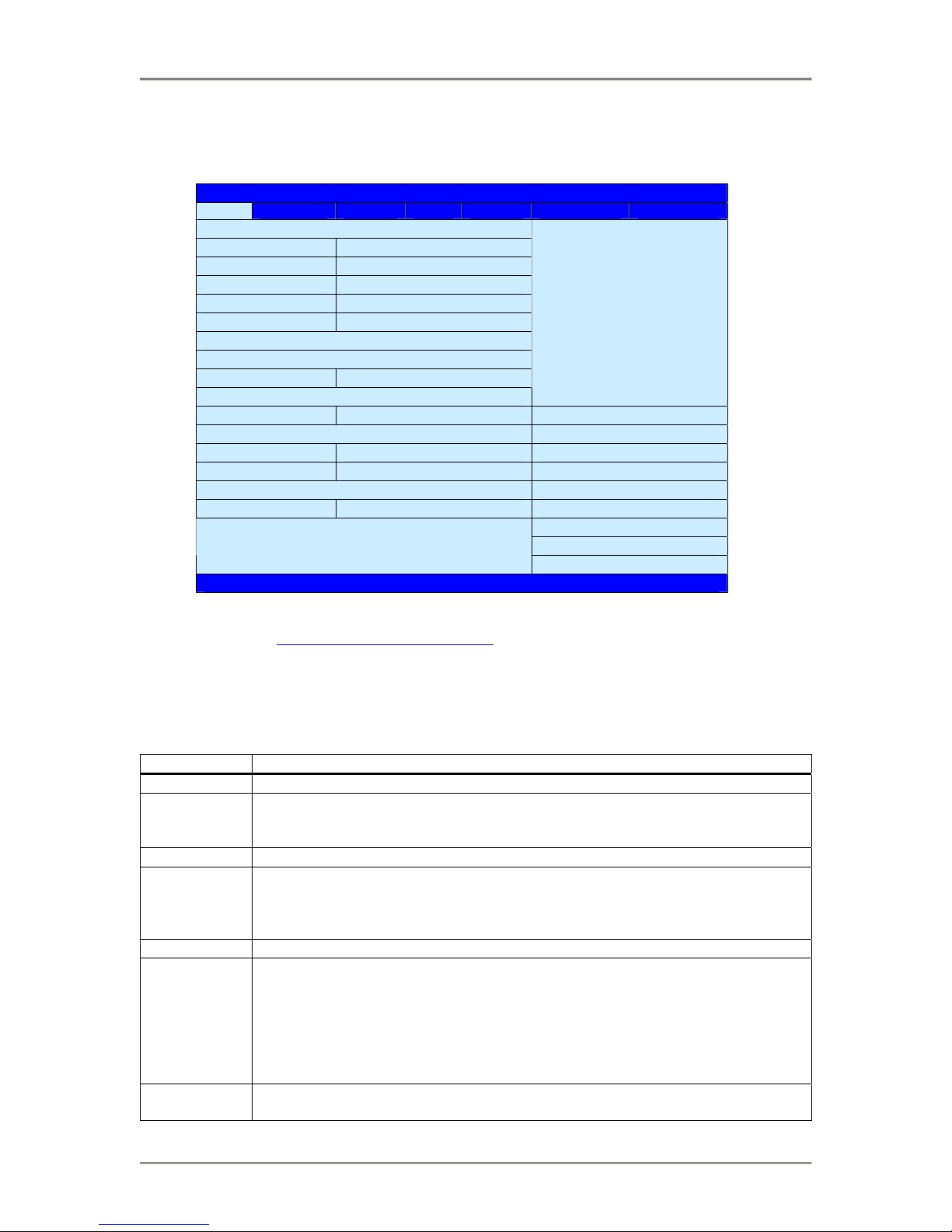
The Aptio TSE BIOS setup menu is the first screen that you can navigate. Each BIOS setup menu option is
described in this user’s guide.
Aptio Setup Utility – Copyright © 2012 American Megatrends Inc.
Main Advanced Chipset Boot Security Save & Exit Event Logs
BIOS Information
BIOS Vendor American Megatrends
Choose the system
default language
Core Version 4.6.5.3
Compliancy UEFI 2.3; PI 1.2
Project Version 0ACAY 0.01 x64
Build Date & Time 07/24/2012 11:00:00
Memory Information
Total Memory 8192 MB (DDR3)
System Language [English]
→← : Select Screen
↑↓ : Select Item
System Date [Mon 07/30/2012] Enter: Select
System Time [14:20:00] +/- : Change Opt.
F1 : General Help
Access Level Administrator F2 : Previous Values
F3 : Optimized Defaults
F4 : Save & Exit
ESC : Exit
Version 2.15.1227, Copyright © 2012 American Megatrends, Inc.
There may be slight differences in the screen shots illustrated in this manual due to Trenton BXT7059
BIOS modifications.
Contact Trenton Technical support for any questions regarding the SHBs’
implementation of Aptio TSE.
Navigation
The Aptio® TSE keyboard-based navigation can be accomplished using a combination of the
keys.(<FUNCTION> keys, <ENTER>, <ESC>, <ARROW> keys, etc.).
Key Description
ENTER The Enter key allows the user to select an option to edit its value or access a sub menu.
→←
Left/Right
The Left and Right <Arrow> keys allow you to select an Aptio TSE screen.
For example: Main screen, Advanced screen, Chipset screen, and so on.
↑↓ Up/Down
The Up and Down <Arrow> keys allow you to select an Aptio TSE item or sub-screen.
+- Plus/Minus The Plus and Minus <Arrow> keys allow you to change the field value of a particular
setup item.
For example: Date and Time.
Enter The <Enter> key allows you to select Aptio TSE fields.
ESC The <Esc> key allows you to discard any changes you have made and exit the Aptio
TSE. Press the <Esc> key to exit the Aptio TSE without saving your changes. The
following screen will appear:
Press the <Enter> key to discard changes and exit. You can also use the <Arrow> key
to select Cancel and then press the <Enter> key to abort this function and return to the
previous screen.
Function keys When other function keys become available, they are displayed in the help screen
along with their intended function.
Trenton Systems Inc. 1-2
Page 11

BXT7059 / BXTS7059 Technical Reference Starting Aptio® TSE
This page intentionally left blank
1-3 Trenton Systems Inc.
Page 12
BXT7059 / BXTS7059 Technical Reference Advanced Setup
Chapter 2 Advanced Setup
Introduction
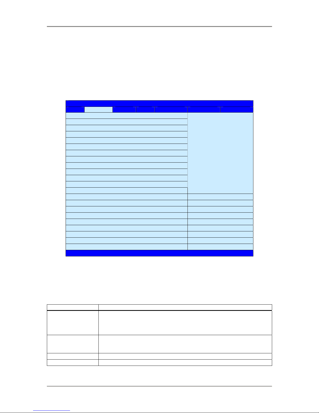
Select the Advanced menu item from the Aptio TSE screen to enter the Advanced BIOS Setup screen. You
can select any of the items in the left frame of the screen, such as PCI Sub-System Settings, ACPI Settings,
CPU Configuration, SATA or SAS Configuration, USB Configuration, and a Super IO configuration if the
SHB is equipped with an optional IOB33. Selecting on of these set-up items will take you to a
configuration sub menu for that item.
Aptio Setup Utility – Copyright © 2012 American Megatrends Inc.
Main Advanced Chipset Boot Security Save & Exit Event Logs
► PCI Subsystem Settings
► ACPI Settings
► Trusted Computing
► WHEA Configuration
► CPU Configuration
► Runtime Error Logging
► SATA Configuration
► SAS Configuration
► Thermal Configuration
► Intel® TXT (LT-SX) Configuration
► USB Configuration
► Super IO Configuration →← : Select Screen
► AMT Configuration ↑↓ : Select Item
► Serial Port Console Redirection Enter: Select
► Network Stack +/- : Change Opt.
F1 : General Help
► iSCSI Configuration F2 : Previous Values
► Intel® 82579LMGigibit Network Connection Cfg. F3 : Optimized Defaults
► Intel® i350 Gigabit Network Connection Cfg. F4 : Save & Exit
► Intel® i350 Gigabit Network Connection Cfg. ESC : Exit
Version 2.15.1227, Copyright © 2012 American Megatrends, Inc.
PCI Sub-System Settings
A number of PCI Express, PCI-X and PCI device settings are available for configuration with this BIOS
parameter. Specific device availability depends on what the BIOS can see during the system boot process.
This setting is used to optimize the operations of off-board cards or devices that interact with the SHB and
the SHB’s BIOS. Listed below are all the available BIOS settings for board’s PCI bus driver and the PCI
Express link interfaces.
Option Description
Above 4G Decoding Disabled/Enabled (bold = default setting) – The system design needs to support
64-bit PCI decoding for this setting to be meaningful. Enabling the setting
allows the SHB to decode the 64-bit capable devices connected to the SHB the
4G-address space. Use caution when enabling this system BIOS parameter.
PCI Latency Timer Timer value selections available: 32 PCI Bus Clocks, 64 PCI Bus Clocks, 96
PCI Bus Clocks, 128 PCI Bus Clocks, 160 PCI Bus Clocks, 192 PCI Bus
Clocks, 224 PCI Bus Clocks, 248 PCI Bus Clocks
VGA Pallet Snoop Disabled/Enabled
PERR# Generation Disabled/Enabled
PCI, PCI-X and PCI
Express Settings
2-1 Trenton Systems Inc.
Page 13

Advanced Setup BXT7059 / BXTS7059 Technical Reference
PCI Sub-System Settings (continued)
Option Description
PERR# Generation Disabled/Enabled
PCI Express Settings There are several sections associated with this BIOS parameter setting as shown
below. Short operational descriptions for each setting can be found in the upper
left corner of the BIOS set-up screen.
PCI Express Device Register Settings
Relaxed Ordering: Disabled/Enabled (bold = default setting)
Extended Tag: Disabled/Enabled
No Snoop: Disabled/Enabled
Maximum Payload: Auto, 128 Bytes, 256 Bytes, 512 Bytes, 1024 Bytes,
2048Bytes, 4096 Bytes
Maximum Read Request: Auto, 128 Bytes, 256 Bytes, 512 Bytes, 1024 Bytes,
2048Bytes, 4096 Bytes
PCI Express Link Register Settings
ASPM Support: Auto/Disabled
Extended Sync: Disabled/Enabled
Link Training Retry: Disabled, 2, 3, 5
Link Training Timeout: 10 – 1000 usec with 100 usec being the default value
Unpopulated Links: Keep Link On, Disabled
PCI Express GEN2
Settings
There are several PCIe 2.0/3.0 sections associated with this BIOS parameter
setting as shown below. Short operational descriptions for each setting can be
found in the upper left corner of the BIOS set-up screen.
PCI Express Device Register Settings
Completion Timeout: Default/Shorter/Longer/Disabled The default setting
enables the normal link timeout range of 50us to 50ms. These BIOS selections
allow you to vary this setting as need in you system design.
ARI Forwarding: Disabled/Enabled
AtomicOp Requester Enable: Disabled/Enabled
AtomicOp Egress Block: Disabled/Enabled
IDO Request Enable: Disabled/Enabled
IDO Completion Enable: Disabled/Enabled
LTR Mechanism Enable: Disabled/Enabled
End-END TLP Prefix B1: Disabled/Enabled
PCI Express GEN2 Link Register Settings
Target Link Speed: Auto, Force to 2.5 GT/s, Force to 5.0 GT/s
Clock Power Management: Disabled/Enabled
Compliance SOS: Disabled/Enabled
Hardware Autonomous Width: Disabled/Enabled
Hardware Autonomous Speed: Disabled/Enabled
Trenton Systems Inc. 2-2
Page 14

BXT7059 / BXTS7059 Technical Reference Advanced Setup
ACPI Settings
This is where you set up your system for use with the ACPI soft control states available on the SHB. The
standard BIOS default is the S1 only (CPU Stop Clock) sleep state. The SHB hardware and BIOS supports
both the S1 and S3 sleep states and these sleep states are available for selection at the operating system
level.
Option Description
Enable ACPI Auto
Disabled/Enabled (bold = default setting)
Configuration
Enable Hibernation Disabled/Enabled
Lock Legacy
Disabled/Enabled
Resources
Trusted Computing Settings
This is where you tell the BIOS that a security device will be used in the system.
Option Description
Security Device
Disabled/Enabled (bold = default setting)
Support
WHEA Configuration
Use this setting to enable or disable the Windows Hardware Error Architecture (WHEA).
Option Description
WHEA Support Disabled/Enabled (bold = default setting)
CPU Configuration
Highlighting and selecting either the socket 0 or socket 1 CPU information line on this menu screen will
pull up a sub-menu that displays the specifics of a processor installed in one of these SHB sockets. The
following table illustrates this useful sub-menu that may be useful in confirming specific processor features
such as min and max core speed, the number of processor cores and cache memory capacities.
Socket 0 or 1 CPU
Information
Description
CPU read by the BIOS upon power up. Here is an example for a processor installed in the CPU 0 socket
of the SHB: Intel® Xeon® CPU E5-2448L 0 @ 1.8GHz
CPU Signature 206d6
Microcode Patch 616
Max CPU Speed 1800 MHz
Min CPU Speed 1200 MHz
Processor Cores 8
Intel HT Technology Supported
Intel VT-x Technology Supported
Intel SMX Technology Supported
L1 Data Cache 32kB x 8
L1 Code Cache 32kB x 8
L2 Cache 256kB x 8
L3 Cache 20480kB
The core speed and 64-bit support status are two parameters for the specific Sandy Bridge-EN / Ivy BridgeEN processors installed on your SHB that are displayed on the second portion of this CPU configuration
main menu.
2-3 Trenton Systems Inc.
Page 15

Advanced Setup BXT7059 / BXTS7059 Technical Reference
CPU Configuration (continued)
The lower portion of the main menu screen contains processor features that you may elect to enable or
disable based on the unique requirements of your system. Here is a partial listing of some of these CPU
parameters:
Option Description
Intel® HyperThreading
Disabled/Enabled - This option allows the user to enable or disable Intel®
Hyper-Threading support on the Intel® Xeon® E5-2400 series (i.e. Sandy
Bridge-EN / Ivy Bridge-EN) processor. By default, this setting is enabled.
(bold = default setting)
Active Processor
Cores
All, 1, 2, 4, 6 - With this setting you may use all of the available cores in the
Intel® Xeon® E5-2400 series (i.e. Sandy Bridge-EN / Ivy Bridge-EN)
processor or on use a subset of the available CPU execution cores. The default
setting for this option is “ALL” and the number of cores to select depends on
the specific processor installed on the SHB.
Limit CPUID
Disabled/Enabled – Disabled when using a Windows® XP operating system
Maximum
Execute Disable Bit Disabled/Enabled – This option allows the user to enable or disable Intel®
Execute Disable Bit feature of the Intel® Xeon® E5-2400 series (i.e. Sandy
Bridge-EN / Ivy Bridge-EN) processor.
Hardware Prefetcher Disabled/Enabled – This setting activates the L2 streamer prefetcher in
processor’s cache
Adjacent Cache Line
Disabled/Enabled
Prefetch
DCU Streamer
Disabled/Enabled
Prefetcher
DCU IP Prefetcher Disabled/Enabled
Intel® Virtualization Disabled/Enabled - This option allows the user to enable or disable Intel®
Virtualization support on the Intel® Xeon® E5-2400 series (i.e. Sandy BridgeEN / Ivy Bridge-EN) processor. By default, this setting is enabled.
Runtime Error Logging Configuration
Use this menu selection to enable or disable the runtime error logging support feature.
Option Description
Runtime Error
Logging
Disabled/Enabled (bold = default setting) - If enabled the following sub-menu
option choices are available:
Memory Correctable Error Threshold Value: 10, 11, 12, 13, 14, 15
PCI Error Logging Support: Disabled/Enabled
Poison Support: Disabled/Enabled
Short operational descriptions for each sub-menu setting can be found in the
upper left corner of the BIOS set-up screen.
SATA Configuration
This is where you can set the parameters for the SATA devices that have been sensed by the SHB during
the boot process. SATA devices connected to ports P27 or P28 on the SHB may operate at data transfer
rate up to 600MB/s. SATA devices connected to P31, P32, P36 or P36 have a maximum data transfer rate
of 300MB/s. What follows is a list of SATA port configuration parameters.
Option Description
SATA Mode Disabled/IDE Mode/AHCI Mode/RAID (bold = default setting) - Short
operational descriptions for each sub-menu setting can be found in the upper left
corner of the BIOS set-up screen.
Serial-ATA
Disabled/Enhanced/Compatible
Controller 0
Serial-ATA
Disabled/Enhanced
Controller 1
Trenton Systems Inc. 2-4
Page 16

BXT7059 / BXTS7059 Technical Reference Advanced Setup
SATA Configuration (continued)
If the SATA Mode selection is changed to the AHCI Mode then the following sub-menu options are
available:
Option Description
Aggressive Link
Power Management
Disabled/Enabled (bold = default setting) - Short operational descriptions for
each sub-menu setting can be found in the upper left corner of the BIOS set-up
screen.
Port 0 through 2 Hot
Disabled/Enabled
Plug
External SATA Port
Disabled/Enabled
3 through 5
Staggered Spin Up Disabled/Enabled – There are three of these option selections available.
If the SATA Mode selection is changed to RAID then the following sub-menu options are available:
Option Description
Port 0 through 2 Hot
Disabled/Enabled
Plug
SAS Configuration
SHB ports P31, P32, P36 or P36 also support SAS devices. This sub-menu selection is where you
configure the system for SAS drives if there are SAS devices connected and sensed by the SHB during the
boot process.
Option Description
SAS Port # Not Present/Disabled/Enabled
Thermal Configuration
This is sub-menu is an enable/disable selection for initializing the Intel® C604 thermal subsystem device.
Option Description
Thermal
Disabled/Enabled
Management
Intel® TXT (LT-SX) Configuration
Currently these BIOS parameters are fixed and the configuration states are listed on the TXT sub-menu.
USB Configuration
The top portion of the menu screen lists the USB devices detected by the BIOS. The lower portion has
several sub-menu selections available where you can set the parameters for the USB devices.
Option Description
Legacy USB Support Enabled/Disabled/Auto (bold = default setting) - Short operational descriptions
for each sub-menu setting can be found in the upper left corner of the BIOS setup screen.
EHCI Hand-Off Disabled/Enabled
Port 60/64 Emulation Disabled/Enabled
USB Hardware
Delays and Timeouts
The following sub-menu selections are used to configure data transfer delays
and timeouts needed for the USB storage devices used in the system design:
USB Transfer Timeout: 1 sec, 5 sec, 10 sec, 20sec
Device Reset Timeout: 10sec, 20sec, 30sec, 40sec
Device Power-Up Delay: Auto, Manual
2-5 Trenton Systems Inc.
Page 17

Advanced Setup BXT7059 / BXTS7059 Technical Reference
Super IO Configuration
The only Super IO component available in a system implementation using a BXT7059 or BXTS7059 is
located on the optional IOB33 module. An IOB33 can plug into the SHBs’ P20 I/O Expansion connector.
If an IOB33 is plugged into the SHB then the Super IO Configuration submenu will be displayed. This
Advanced Setup sub-menu allows you to configure the system ports connected to the IOB33s’ Super I/O
component.
NOTE: The following Super IO settings are only valid when an optional Trenton IOB33 I/O Board is
installed on the BXT7059 or BXTS7059 SHB.
Floppy Disk Controller
This option allows you to enable or disable the floppy drive controller on your platform.
Option Description
Disabled Set this value to prevent the BIOS from detecting the onboard floppy drive controller.
Enabled Set this value to allow the BIOS to use the onboard floppy drive controller. This is the
default setting.
Floppy Device Mode
This option allows you to enable or disable write-protection of floppy disks.
Option Description
Read Write Set this value to allow writing to floppy disks. This is the default setting.
Write Protect Set this value to prevent writing to floppy disks.
Serial Port 0 Configuration
This option specifies the base I/O port address and Interrupt Request address of serial port 0. The Optimal
setting is 3F8/IRQ4. The Fail-Safe default setting is Disabled.
Option Description
Disabled Set this value to prevent the serial port from accessing any system resources. When
this option is set to Disabled, the serial port physically becomes unavailable.
3F8/IRQ4 Set this value to allow the serial port to use 3F8 as its I/O port address and IRQ 4 for
the interrupt address. This is the default setting. The majority of serial port 1 or COM1
ports on computer systems use IRQ4 and I/O Port 3F8 as the standard setting. The
most common serial device connected to this port is a mouse. If the system will not use
a serial device, it is best to set this port to Disabled.
2F8/IRQ3 Set this value to allow the serial port to use 2F8 as its I/O port address and IRQ 3 for
the interrupt address. If the system will not use a serial device, it is best to set this port
to Disabled.
3E8/IRQ4 Set this value to allow the serial port to use 3E8 as its I/O port address and IRQ 4 for
the interrupt address. If the system will not use a serial device, it is best to set this port
to Disabled.
2E8/IRQ3 Set this value to allow the serial port to use 2E8 as its I/O port address and IRQ 3 for
the interrupt address. If the system will not use a serial device, it is best to set this port
to Disabled.
Trenton Systems Inc. 2-6
Page 18

BXT7059 / BXTS7059 Technical Reference Advanced Setup
Super IO Configuration (continued)
Serial Port 1 Configuration
This option specifies the base I/O port address and Interrupt Request address of serial port 1. The Optimal
setting is 2F8/IRQ3. The Fail-Safe setting is Disabled.
Option Description
Disabled Set this value to prevent the serial port from accessing any system resources. When
this option is set to Disabled, the serial port physically becomes unavailable.
3F8/IRQ4 Set this value to allow the serial port to use 3F8 as its I/O port address and IRQ 4 for
the interrupt address. If the system will not use a serial device, it is best to set this port
to Disabled.
2F8/IRQ3 Set this value to allow the serial port to use 2F8 as its I/O port address and IRQ 3 for
the interrupt address. This is the default setting. The majority of serial port 2 or COM2
ports on computer systems use IRQ3 and I/O Port 2F8 as the standard setting. The
most common serial device connected to this port is an external modem. If the system
will not use an external modem, set this port to Disabled.
Note: Most internal modems require the use of the second COM port and use 3F8 as
its I/O port address and IRQ 4 for its interrupt address. This requires that the Serial
Port2 Address be set to Disabled or another base I/O port address and Interrupt
Request address.
3E8/IRQ4 Set this value to allow the serial port to use 3E8 as its I/O port address and IRQ 4 for
the interrupt address. If the system will not use a serial device, it is best to set this port
to Disabled.
2E8/IRQ3 Set this value to allow the serial port to use 2E8 as its I/O port address and IRQ 3 for
the interrupt address. If the system will not use a serial device, it is best to set this port
to Disabled.
2-7 Trenton Systems Inc.
Page 19

Advanced Setup BXT7059 / BXTS7059 Technical Reference
Parallel Port Configuration
This option enables/disables the parallel port on the IOB33 and is used to configure the I/O address and
operating mode for the parallel port. The default setting is AUTO, but you may elect to change this as
needed.
Option Description
Parallel Port Enable/Disable - Set this value to disable prevent the parallel port from accessing any
system resources. When the value of this option is set to Disabled, the printer port
becomes unavailable. Enabled is the BIOS default setting
Change
Settings
The default setting for this operation is AUTO, which allows the board’s BIOS to
automatically assign system resources to the IOB33 parallel port. You may also select
specific IO address and IRQ setting values from the list below:
IO=378h; IRQ=5;
IO=378h; IRQ=3,4,5,6,710,11,12;
IO=278h; IRQ=3,4,5,6,710,11,12;
IO=3BCh; IRQ=3,4,5,6,710,11,12;
IO=378h;
IO=278h;
IO=3BCh;
Note: The majority of parallel ports on computer systems use IRQ7 and I/O Port 378H
as the standard setting.
Device Mode Standard (STD) Printer Mode is the default value for this print mode selection. Other
parallel printer operating modes available are:
SPP Mode
EPP-1.9 and SPP Mode
EPP-1.7 and SPP Mode
ECP Mode
ECP-1.9 and SPP Mode
ECP-1.7 and SPP Mode
The EPP modes enable the parallel port to be used with devices that adhere to the
Enhanced Parallel Port (EPP) specification. EPP uses the existing parallel port signals
to provide asymmetric bi-directional data transfer driven by the host device.
The ECP modes enable the parallel port to be used with devices that adhere to the
Extended Capabilities Port (ECP) specification. ECP uses the DMA protocol to
achieve data transfer rates up to 2.5 Megabits per second. ECP provides symmetric bi-
directional communication.
AMT Configuration
This BIOS menu selection is used to enable/disable Intel AMT 7.0 support on the SHB. The default setting
for the Intel AMT configuration setting is: Enabled. The table below lists the board configuration settings
related to Intel AMT support.
Option Description
AMT Enable/ Disable -- Default setting is Enabled.
Un-configure
AMT/ME
Enable/ Disable -- Default setting is Disabled. When enabled this setting allows you
to configure the management engine associated with Intel AMT operations without
requiring a password. Use caution when enabling this setting.
Watchdog
Timer (WDT)
OS WDT
Enable/ Disable -- Default setting is Disabled. When enabled you may input
operating system and BIOS time-out values
Input a valid timer value between 0 and 65535
Timer
BIOS WDT
Input a valid timer value between 0 and 65535
Timer
Trenton Systems Inc. 2-8
Page 20

BXT7059 / BXTS7059 Technical Reference Advanced Setup
Serial Port Console Redirection Configuration
The SHB must have an optional IOB33 installed in order for the BIOS setting to apply. Serial port console
redirection is available for use on the IOB33’s COM0 and COM1 serial communication ports. When
selected, the serial port console redirection configuration BIOS screen displays the following parameters.
Option Description
COM0
Console
Enabled/ Disabled -- Default setting is Enabled. Note: The console redirection
settings shown below will be unavailable if the Disabled option is selected.
Redirection
COM0
Console
Redirection
Settings
Use this setting to specify how the host computer and the remote computer will
exchange data via the COM0 port. Both computers need to have compatible settings.
Here are the available COM0 settings:
Terminal Type: VT100. VT100+, VT-UTF8, ANSI
Bits per second: 9600, 19200, 38400, 57600, 115200
Data Bits: 7, 8
Parity: None, Even, Odd, Mark, Space
Stop Bits: 1, 2
Flow Control: None, Hardware RTS/CTS
VT-UTF8Combo Key Support: Disabled, Enabled
Recorder Mode: Disabled, Enabled
Resolution 100x31: Disabled, Enabled
Legacy OS Redirection: 80x24, 80x25
Putty Keypad: VT100, LINUX, XTERMR6, SCO, ESCN, VT400
Redirection After BIOS: Always Enable, BootLoader
COM1
Console
Enabled/ Disabled -- Default setting is Enabled. Note: The console redirection
settings shown below will be unavailable if the Disabled option is selected.
Redirection
COM1
Console
Redirection
Settings
Use this setting to specify how the host computer and the remote computer will
exchange data via the COM1 port. Both computers need to have compatible settings.
Here are the available COM1 settings:
Out-of-Band Management Port: COM0, COM1(PCI Bus, DEV0,FUN C0) (Disabled)
Terminal Type: VT100. VT100+, VT-UTF8, ANSI
Bits per second: 9600, 19200, 57600, 115200
Flow Control: None, Hardware RTS/CTS
Data Bits: Fixed at 8
Parity: Fixed at None
Stop Bits: Fixed at 1
Network Stack Configuration
This advanced setup BIOS setting enables or disables the PXE and UEFI network stacks and the default
setting is: Enabled.
Intel® 82579LM Gigabit Network Configuration – Backplane LAN
Here is where you setup the interface parameters for the Ethernet PHY device that routes a Gigabit LAN
down to the SHB’s edge connector C for use on a PICMG 1.3 LAN-enabled backplane. Listed below are
the available network configuration parameters for the board’s backplane LAN.
Option Description
NIC
Configuration
Link Speed: AutoNeg, 10Mbps Half, 10Mbps Full, 100Mbps Half, 100Mbps Full
Wake on LAN: Enabled/Disabled (bold = default setting)
2-9 Trenton Systems Inc.
Page 21

Advanced Setup BXT7059 / BXTS7059 Technical Reference
Intel® i350 Gigabit Network Configuration – LAN0
Here is where you setup the interface parameters for the Ethernet controller that routes a LAN0 Gigabit
interface to the SHB’s I/O plate. LAN0 is connector P4A on the SHB. Listed below are the available
network configuration parameters.
Option Description
NIC
Configuration
Link Speed: AutoNeg, 10Mbps Half, 10Mbps Full, 100Mbps Half, 100Mbps Full
Wake on LAN: Enabled/Disabled (bold = default setting)
Intel® i350 Gigabit Network Configuration – LAN1
Here is where you setup the interface parameters for the Ethernet controller that routes a LAN1 Gigabit
interface to the SHB’s I/O plate. LAN0 is connector P4B on the SHB. Listed below are the available
network configuration parameters.
Option Description
NIC
Configuration
Link Speed: AutoNeg, 10Mbps Half, 10Mbps Full, 100Mbps Half, 100Mbps Full
Wake on LAN: Enabled/Disabled (bold = default setting)
Trenton Systems Inc. 2-10
Page 22

BXT7059 / BXTS7059 Technical Reference Advanced Setup
This page intentionally left blank
2-11 Trenton Systems Inc.
Page 23

BXT7059 / BXTS7059 Technical Reference Chipset Configuration Setup
Chapter 3 Chipset Configuration Setup
Introduction
The term “chipset” is a bit of a misnomer for the Trenton BXT7059 and BXTS7059. The “chipset” on
these SHBs is really a single component called a “Platform Controller Hub” or PCH. Specifically, the
Trenton BXT7059 and BXTS7059 both feature the Intel® C604 PCH. This new PCH; developed under the
code name Patsburg-B, is a device that combines many of the capabilities that were previously contained in
individual North Bridge and South Bridge chipset components. The following section covers the set-up
parameters of what could thought of as the North Bridge and South Bridge sections of the Intel® C604
Platform Controller Hub.
North Bridge Configuration
The North Bridge Configuration menu item allows the user to do the following:
Option Description
Sandy Bridge-EN /
Ivy Bridge-EN IOH
Configuration
The Input Output Hub (IOH) configuration menu allows the user to view,
enable or disable the Intel® Virtualization Technology for Directed I/O feature
of the processors. This menu selection is also used to configure the PCI
Express links out of the CPUs. Short operational descriptions for each sub-menu
setting can be found in the upper left corner of the BIOS set-up screen. The
following sub-menu option choices are available for configuration:
Intel® VT for Directed I/O Configuration – Disabled/Enabled (bold = default
setting)
The following configuration choices are available if Intel VT-d is enabled:
Coherency Support: Disabled/Enabled
ATS Support: Disabled/Enabled
Intel® I/O Acceleration Technology: Disabled/Enabled
DCA (Direct Cache Access) Support: Disabled/Enabled
VGA Priority: Offboard
Target VGA: Currently fixed at VGA from CPU0
GEN3 Equalization WA’s (workarounds): Disabled
IOH Resource Selection: Auto/Manual
MMIOH Size: 1G, 2G, 4G, 8G, 16G, 32G, 64G, 126G
MMCFG Base: 0x80000000, 0xA0000000, 0xC0000000
IOH 0 PCIe Port Bifurcation Control:
IOU1 – PCIe Port: x4x4, x8
Port 1A Link Speed: GEN1, GEN2, GEN3
Port 1B Link Speed: GEN1, GEN2, GEN3
IOU2 – PCIe Port: x4x4x4x4, x4x4x8, x8x4x4, x8x8, x16
Port 2A Link Speed: GEN1, GEN2, GEN3
Port 2B Link Speed: GEN1, GEN2, GEN3
IOU3 – PCIe Port: Auto, x4x4x4x4, x4x4x8, x8x4x4, x8x8, x16
Note: The number of link speed selections made visible will vary based on the
IOU# PCIe port selection; e.g. the x4x4x4x4 option will yield four PCIe link
speed selections. No speed selections are seen with the Auto option because the
SHB / backplane combination will auto-negotiate link bifurcation and link
speed.
3-1 Trenton Systems Inc.
Page 24

Chipset Configuration Setup BXT7059 / BXTS7059 Technical Reference
IOH Configuration Parameters (continued):
IOH 0 PCIe Port Direct I/O Control:
Port 0A: Disabled/Enabled
Port 1A: Disabled/Enabled
Port 1B: Disabled/Enabled
Port 2A: Disabled/Enabled
Port 2B: Disabled/Enabled
Port 3A: Disabled/Enabled
Port 3B: Disabled/Enabled
Port 3C: Disabled/Enabled
Port 3D: Disabled/Enabled
IOH 1 PCIe Port Bifurcation Control:
IOU1 – PCIe Port: x4x4, x8
Port 1A Link Speed: GEN1, GEN2, GEN3
Port 1B Link Speed: GEN1, GEN2, GEN3
IOU2 – PCIe Port: x4x4x4x4, x4x4x8, x8x4x4, x8x8, x16
Port 2A Link Speed: GEN1, GEN2, GEN3
Port 2B Link Speed: GEN1, GEN2, GEN3
IOU3 – PCIe Port: Auto, x4x4x4x4, x4x4x8, x8x4x4, x8x8, x16
IOH 1 PCIe Port Direct I/O Control:
Port 0A: Disabled/Enabled
Port 1A: Disabled/Enabled
Port 1B: Disabled/Enabled
Port 2A: Disabled/Enabled
Port 2B: Disabled/Enabled
Port 3A: Disabled/Enabled
Port 3B: Disabled/Enabled
Port 3C:
Disabled/Enabled
Port 3D: Disabled/Enabled
QPI Configuration This option allows the user to view, select or set to auto the link frequency of
the Intel® Quick Path Interconnect or Intel QPI between the dual processors on
a BXT7059 board. Trenton recommends using the QPI link defaults.
Isoc: Disabled/Enabled
QPI Link Speed Mode: Slow, Fast
QPI Link Speed Selection: Auto, 6.4GT/s, 7.2GT/s, 8.0GT/s
QPI LinkOs: Disabled/Enabled
QPI LinkOp: Disabled/Enabled
QPI Link1: Disabled/Enabled
Compatibility RID Disabled/Enabled
Memory
Configuration
The upper portion of this BIOS menu lists the specific memory DIMM(s) that
are installed in the board and sensed upon start up as well the current memory
interface configuration settings or BIOS defaults. Listed below are the
available memory configuration parameters:
Memory Mode: Independent, Mirroring, Lock Step, Sparing
DRAM RAPL BWLIMIT: 0, 1, 8, 16
Perfmon and DEX Devices: Hide, Unhide
DRAM RAPL Mode: Disabled, DRAM RAPL MODE0, DRAM RAPL MODE1
NUMA: Disabled/Enabled
MPST Support: Disabled/Enabled
DDR Speed: Auto, Force DDR3 800, Force DDR3 1066, Force DDR3 1333,
Force DDR3 1600
Channel Interleaving: Auto, 1 Way, 2 Way, 3 Way, 4 Way
Trenton Systems Inc. 3-2
Page 25

BXT7059 / BXTS7059 Technical Reference Chipset Configuration Setup
Memory Configuration Parameters (continued):
Rank Interleaving: Auto, 1 Way, 2 Way, 3 Way, 4 Way
Patrol Scrub: Disabled/Enabled
Demand Scrub: Disabled/Enabled
Data Scrambling: Disabled/Enabled
Device Tagging: Disabled/Enabled
Rank Margin: Disabled/Enabled
Thermal Throttling: Disabled, OLTT, CLTT
OLTT Peak BW %: valid values are between 25 an d 100, Default = 50
Altitude: Auto, 300M, 900M, 1500M, 3000M
Serial Message Debug: Minimum, Maximum, Trace, Memory Training
DIMM Information: This is an informational menu screen that displays the
memory channels and nodes for each processor along with any DIMM
information that is read by the BIOS during the boot process.
South Bridge Configuration
The upper porting of the menu screen provides PCH product code name and the stepping of the particular
Intel® C604 PCH this is installed on the board. Accessing the South Bridge Configuration option allows
the user to do configure the following parameters:
Option Description
PCH Compatibility
RID
Disabled/Enabled is the option parameter choice for this selection. Any option
selection listed with bold text indicates that this is the BIOS default setting.
SMBus Controller This option allows the user to enable or disable the SMBus Controller in the
Intel® C604.
SW SMI Timer Disabled/Auto
GbE Controller This option is fixed in the enable mode. This internal controller provides the
LAN interface that is routed via the Intel® 82579LM Ethernet PHY to board’s
edge connector C for use on a PICMG 1.3 backplane. This setting does not
affect the operation of the independent Intel® i350 Ethernet Controller that
drives the two LAN ports on the SHB’s I/O plate.
Wake on LAN from
S5
Restore AC Power
Loss
This option allows the user to enable or disable wake on LAN feature derived
from an ACPI S5 shutdown event
This option allows the user to determine how the system will come back up
when power is restored after an unplanned power interruption. The available
options are: Power Off, Power On or Last State.
SLP_S4Assertion
Stretch Enable
Disabled/Enabled
The following sub-menu selection is available when this parameter is enabled:
SLP_S4 Assertion Width: 1- 2 seco nds , 2- 3 se con ds , 3-4 seconds, 4-5 seconds
Deep Sx This setting supports the deep sleep S4 and S5 states primarily used in mobile
devices. The available options include: Disabled, Enabled in S5(Battery),
Enabled in S5, Enabled in S4 and S5(Battery), Enabled in S4 and S5
Disable SCU Devices Disabled/Enabled
Onboard SAS
Disabled/Enabled
Oprom/Driver
Onboard SATA
Disabled/Enabled
RAID Oprom/Driver
High Precision Event
Disabled/Enabled
Timer
3-3 Trenton Systems Inc.
Page 26

Chipset Configuration Setup BXT7059 / BXTS7059 Technical Reference
South Bridge Configuration (continued)
PCI Express Ports
Configuration
These settings are available for configuring the PCI Express links used for
component interconnects on the board and for the B0 PCIe link routed to the
SHB’s edge connector. The default setting for each port is set to Auto and
Trenton highly recommends leaving these settings alone. These internal PCIe
ports drive on-board components and turning them off will disable critical SHB
and system functions
The available options include:
PCI Express Port 1: Disabled, Enabled, Auto
PME SCI: Disabled, Enabled
PCI Express Port 2: Disabled, Enabl ed, Auto
PME SCI: Disabled, Enabled
PCI Express Port 3: Disabled, Enabled, Auto
PME SCI: Disabled, Enabled
PCI Express Port 4: Disabled, Enabled, Auto
PME SCI: Disabled, Enabled
PCI Express Port 5: Disabled, Enabled, Auto
PME SCI: Disabled, Enabled
PCI Express Port 6: Disabled, Enabled, Auto
PME SCI: Disabled, Enabled
PCI Express Port 7: Disabled, Enabled, Auto
PME SCI: Disabled, Enabled
PCI Express Port 8: Disabled, Enabled, Auto
PME SCI: Disabled, Enabled
PCI Sub Decode Disabled/Enabled – If enabled the following sub-menus selection appears.
Port Select: PCI Express Port 1, PCI Express Port 2, PCI Express Port 3, PCI
Express Port 4, PCI Express Port 5, PCI Express Port 6, PCI Express Port 7,
PCI Express Port 8
DMI Vc1 Control Disabled/Enabled
DMI Vcp Control Disabled/Enabled
USB Configuration This option allows the user to Enable or Disable the various USB ports inside
the Intel® C604 PCH. These internal USB ports drive the USB interface
connections to the SHBs I/O plate and down to edge connector C for us on a
PICMG 1.3 backplane.
The available option parameters include:
EHCI Controller 1: Disabled/Enabled
EHCI Controller 2: Disabled/Enabled
USB Port #: Disabled/Enabled
Note: # equals the USB port number of 1 through 13
Intel ME Subsystem
Configuration
The Intel® Management Engine or Intel® ME is a portion of the Intel® C604
firmware stored in the boards SPI devices and is used in conjunction such
features Intel® AMT and the PCI Express GEN3 link parameters. Exercise
caution if you elect to change the following default parameters:
ME Sub System: Disabled/Enabled
ME Temporary Disable: Disabled/ Enabled
End of Post Message: Disabled/Enabled
Execute MEBx: Disabled/Enabled
Trenton Systems Inc. 3-4
Page 27

BXT7059 / BXTS7059 Technical Reference Chipset Configuration Setup
This page intentionally left blank
3-5 Trenton Systems Inc.
Page 28

BXT7059 / BXTS7059Technical Reference Boot Setup
Chapter 4 Boot Setup
Introduction
Select the Boot Setup menu item from the Aptio TSE screen to enter the BIOS Setup screen. The Boot
menu option allows you to access the following the following boot setup features.
Boot Configuration
Enter the number of seconds you wish the board to wait for a setup key activation key.
Option Description
Setup Prompt
Timeout
Bootup
Numlock State
Quite Boot Disabled/Enabled - this default value allows the computer system to display the POST
Fast Boot Disabled/Enabled – this default setting allows the computer system to perform a full
The next four BIOS settings on this screen are:
These are special purpose BIOS settings and should remain in the default positions. Contact Trenton’s
technical support team if you need to use these BIOS settings.
Acceptable values: 0 to 65535 (0xFFFF) and the default value is 1
Note: 65535 means the BIOS will wait indefinitely for a key press
On/Off – Selects the keyboard numlock state
messages. The enabled option is used for displaying a custom OEM logo during
POST.
boot with a full set of devices. In full configuration mode, all devices are detected and
initialized. The enabled option allows the computer system to do a minimal boot. In
minimal configuration mode, only the devices that are necessary to boot the system are
detected and initialized as defined in the option settings below:
Skip VGA: Disabled/ Enabled
Skip USB: Disabled/ Enabled
Skip PS2: Disabled/ Enabled
• Gate20 Active: Upon Request, Always
• Option ROM Messages: Force BIOS, Keep Current
• INT19 Trap Response: Intermediate, Postponed
• CSM Support: Disabled, Enabled, Auto
4-1 Trenton Systems Inc.
Page 29

Boot Setup BXT7059 / BXTS7059 Technical Reference
Boot Option Priorities
The following settings allow you to set the system boot priority of where to pull the BIOS settings from in
order to perform a system boot. You can set three priority levels and the number of available options
within each priority is based on the devices connected to the SHB. Here is an example of potential boot
options.
Boot Option #1 Boot Option #2
UEFI: Built-in EFI Shell SATA Hard Drive [HD type info]
SATA Hard Drive [HD type info] UEFI: Built-in EFI Shell
USB Flash Hub [USB type info] USB Flash Hub [USB type info]
Disabled Disabled
Any other devices connected to SHB and the system would show up under each option in the above listing.
CSM Parameters
The Compatibility Support Module (CSM) parameters are used BIOS compatibility with non-UEFI
compliant operating systems.
Option Description
Launch CSM Auto, Always, Never
Boot Option
UEFI and Legacy, Legacy Only, UEFI Only
Filter
Launch PXE
Do not launch, UEFI only, Legacy only, Legacy first, UEFI first
OpROM
policy
Launch
Do not launch, UEFI only, Legacy only, Legacy first, UEFI first
Storage
OpROM
Launch Video
Do not launch, UEFI only, Legacy only, Legacy first, UEFI first
OpROM
policy
Other PCI
UEFI OpROM, Legacy OpROM
Device ROM
Trenton Systems Inc. 4-2
Page 30

BXT7059 / BXTS7059Technical Reference Boot Setup
This page intentionally left blank
4-3 Trenton Systems Inc.
Page 31

BXT7059 / BXTS7059Technical Reference Security
Chapter 5 Security
Two Levels of Password Protection
Security Setup provides both a Supervisor and a User password. If you use both passwords, the Supervisor
password must be set first.
The system can be configured so that all users must enter a password every time the system boots or when
Setup is executed, using either or either the Supervisor password or User password.
The Supervisor and User passwords activate two different levels of password security. If you select
password support, you are prompted for a 1-20 character password. Type the password on the keyboard.
The password does not appear on the screen when typed. Make sure you write it down. If you forget it, you
must drain NVRAM and reconfigure.
Remember the Password
Keep a record of the new password when the password is changed. If you forget the password, you must
erase the system configuration information in NVRAM. See (Deleting a Password) for information about
erasing system configuration information.
Security Setup
The Security setup menu item allows the user to do the following:
Option Description
User Password This option allows the user to set a user level password for the BIOS.
Admin Password This option allows the user to set an administrative level password for the
BIOS.
5-1 Trenton Systems Inc.
Page 32

Security BXT7059 / BXTS7059 Technical Reference
This page intentionally left blank
Trenton Systems Inc. 5-2
Page 33

BXT7059 / BXTS7059 Technical Reference Saving & Exiting Setup
Chapter 6 Saving and Exiting BIOS Setup and Restoring Defaults
Introduction
There are four methods of saving BIOS changes and leaving Aptio TSE listed at the top of this screen:
1 - Save Changes & Exit
When you have completed the system configuration changes, select this option to save your BIOS changes
and leave Aptio TSE. You will need to reboot the computer for the new system configuration parameters
to take effect.
Select Save Changes & Exit from the Exit menu and press <Enter>.
Save Configuration Changes and Exit Now?
[YES] [NO] appears in the window. Select YES to save changes and exit.
2 - Discard Changes & Exit
Select this option to quit Aptio TSE without making any permanent changes to the system configuration.
Select Discard Changes & Exit from the Exit menu and press <Enter>.
Discard Changes and Exit Setup Now?
[YES] [NO] Select YES to discard changes and exit.
3 - Save Changes & Reset
When you have completed the system configuration changes, select this option to save the BIOS changes,
leave Aptio TSE and reset the computer so the new system configuration parameters can take effect.
Select Save Changes & Reset from the Exit menu and press <Enter>.
Save Configuration Changes and Exit Now?
[YES] [NO] appears in the window. Select YES to save changes and reset.
4 - Discard Changes & Reset
Choose this option if you decide to discard your BIOS changes, but what to reset the system upon leaving
Aptio TSE.
Select Discard Changes & Reset from the Exit menu and press <Enter>.
Discard Configuration Changes and Exit Now?
[YES] [NO] appears in the window. Select YES to discard changes and reset.
The following two screen options allow save or discard BIOS changes without leaving Aptio TSE:
Save Changes [YES] [NO]
Discard Changes [YES] [NO]
(i.e. load previous values)
6-1 Trenton Systems Inc.
Page 34

Saving & Exiting Setup BXT7059 &BXTS7059 Technical Reference
The following menu options for BIOS defaults are available:
Restore Defaults
Aptio TSE automatically sets all Aptio TSE options to a complete set of factory default settings when you
select this option.
Select restore defaults from the Exit menu and press <Enter>.
Restore Defaults?
[YES] [NO] appears in the window. Select YES to load restore defaults.
Save as User Defaults
With this option, the BIOS changes done so far by the user are saved as User Defaults.
Select save as user defaults from the Exit menu and press <Enter>.
Save as User Defaults?
[YES] [NO] appears in the window. Select YES to save user defaults.
Restore User Defaults
Aptio TSE automatically sets all Aptio TSE options to a complete set of user default settings when you
select this option.
Select restore user defaults from the Exit menu and press <Enter>.
Restore User Defaults?
[YES] [NO] appears in the window. Select YES to load restore user defaults.
Boot Overide
Select this option to allow a system boot override from either a specific device connected to the SHB such
as a SATA HDD or from the BIOS’ UEFI Shell.
Save configuration and reset?
[YES] [NO] appears in the window. Select YES to load restore user defaults.
Trenton Systems Inc. 6-2
Page 35

BXT7059 / BXTS7059 Technical Reference Saving & Exiting Setup
This page intentionally left blank
6-3 Trenton Systems Inc.
Page 36

BXT7059 / BXTS7059 Technical Reference Saving & Exiting Setup
Chapter 7 SMBIOS Event Log
Change SMBIOS Event Log Settings
Use the Aptio TSE menu screen options to set up the system event log reporting format and configuration
options for the BIOS.
View SMBIOS Event Log
This read-only menu screen displays the events recorded in the BIOS event log. An event’s error code and
severity along with the data an time that the event occurred are displayed on this screen.
View SYSTEM Event Log
This read-only menu screen displays the events recorded in the BIOS event log. An event’s error code and
severity along with the data an time that the event occurred are displayed on this screen.
7-1 Trenton Systems Inc.
Page 37

BXT7059 / BXTS7059 Technical Reference Appendix A
Appendix A BIOS Messages
Introduction
A status code is a data value used to indicate progress during the boot phase. These codes are outputted to
I/O port 80h on the SHB. Aptio 4.x core outputs checkpoints throughout the boot process to indicate the
task the system is currently executing. Status codes are very useful in aiding software developers or
technicians in debugging problems that occur during the pre-boot process.
Aptio Boot Flow
While performing the functions of the traditional BIOS, Aptio 4.x core follows the firmware model
described by the Intel Platform Innovation Framework for EFI (“the Framework”). The Framework refers
the following “boot phases”, which may apply to various status code descriptions:
• Security (SEC) – initial low-level initialization
1
• Pre-EFI Initialization (PEI) – memory initialization
• Driver Execution Environment (DXE) – main hardware initialization
• Boot Device Selection (BDS) – system setup, pre-OS user interface & selecting a bootable
device (CD/DVD, HDD, USB, Network, Shell, …)
1
Analogous to “bootblock” functionality of legacy BIOS
2
Analogous to “POST” functionality in legacy BIOS
BIOS Beep Codes
The Pre-EFI Initialization (PEI) and Driver Execution Environment (DXE) phases of the Aptio BIOS use
audible beeps to indicate error codes. The number of beeps indicates specific error conditions.
PEI Beep Codes
# of Beeps Description
1 Memory not Installed
1 Memory was installed twice (InstallPeiMemory routine in PEI Core called twice)
2 Recovery started
3 DXEIPL was not found
3 DXE Core Firmware Volume was not found
7 Reset PPI is not available
4 Recovery failed
4 S3 Resume failed
2
A-1 Trenton Systems Inc.
Page 38

Appendix A BXT7059 / BXTS7059 Technical Reference
N
N
DXE Beep Codes
# of Beeps Description
4 Some of the Architectural Protocols are not available
5
5
1 Invalid password
6 Flash update is failed
7 Reset protocol is not available
8 Platform PCI resource requirements cannot be met
o Console Output Devices are found
o Console Input Devices are found
Trenton Systems Inc. A-2
Page 39

BXT7059 / BXTS7059 Technical Reference Appendix A
BIOS Status Codes
As the POST (Power On Self Test) routines are performed during boot-up, test codes are displayed on Port
80 POST code LEDs 0, 1, 2, 3, 4, 5, 6 and 7. These LED are located on the top of the SHB, just above the
board’s battery socket. The POST Code LEDs and are numbered from right (position 1 = LED0) to left
(position 8 – LED7).
The POST code checkpoints are the largest set of checkpoints during the BIOS pre-boot process. The
following chart is a key to interpreting the POST codes displayed on LEDs 0 through 7 on the BXT7059
and BXTS7059 SHBs. Refer to the board layout in the Specifications chapter for the exact location of the
POST code LEDs.
The HEX to LED chart in the POST Code LEDs section will serve as a guide to interpreting specific BIOS
status codes.
BIOS Status POST Code LEDs
As the POST (Power On Self Test) routines are performed during boot-up, test codes are displayed on Port
80 POST code LEDs 0, 1, 2, 3, 4, 5, 6 and 7. These LED are located on the top of the SHB, just above the
board’s battery socket. The POST Code LEDs and are numbered from right (position 1 = LED0) to left
(position 8 – LED7).
The POST code checkpoints are the largest set of checkpoints during the BIOS pre-boot process. The
following chart is a key to interpreting the POST codes displayed on LEDs 0 through 7 on the BXT7059
and BXTS7059 SHBs. Refer to the board layout in the Specifications chapter for the exact location of the
POST code LEDs.
Upper Nibble (UN) Lower Nibble (LN)
Hex.
Value
0
1
2
3 Off Off On On 3 Off Off On On
4 Off On Off Off 4 Off On Off Off
5 Off On Off On 5 Off On Off On
6 Off On On Off 6 Off On On Off
7 Off On On On 7 Off On On On
8 On Off Off Off 8 On Off Off Off
9 On Off Off On 9 On Off Off On
A On Off On Off A On Off On Off
B On Off On On B On Off On On
C On On Off Off C On On Off Off
D On On Off On D On On Off On
E On On On Off E On On On Off
F On On On On F On On On On
LED7 LED6 LED5 LED4
Off Off Off Off
Off Off Off
Off Off
On
On
Off
Hex.
Value
0
1 Off Off Off On
2
LED3 LED2 LED1 LED0
Off Off Off Off
Off Off
On
Off
Upper Nibble
Lower Nibble
7 6 5 4 3 2 1 0
BXT7059 & BXTS7059 POST Code LEDs
A-3 Trenton Systems Inc.
Page 40

Appendix A BXT7059 / BXTS7059 Technical Reference
N
N
N
Status Code Ranges
Status Code Range Description
0x01 – 0x0F
0x10 – 0x2F
0x30 – 0x4F
0x50 – 0x5F
0x60 – 0xCF
0xD0 – 0xDF
0xE0 – 0xE8
0xE9 – 0xEF
0xF0 – 0xF8
0xF9 – 0xFF
SEC Status Codes & Errors
PEI execution up to and including memory detection
PEI execution after memory detection
PEI errors
DXE execution up to BDS
DXE errors
S3 Resume (PEI)
S3 Resume errors (PEI)
Recovery (PEI)
Recovery errors (PEI)
SEC Status Codes
Status Code Description
0x0
Progress Codes
0x1 Power on. Reset type detection (soft/hard).
0x2 AP initialization before microcode loading
0x3
0x4 South Bridge initialization before microcode loading
0x5 OEM initialization before microcode loading
0x6 Microcode loading
0x7 AP initialization after microcode loading
0x8
0x9 South Bridge initialization after microcode loading
0xA OEM initialization after microcode loading
0xB Cache initialization
SEC Error Codes
0xC – 0xD Reserved for future AMI SEC error codes
0xE Microcode not found
0xF Microcode not loaded
ot used
orth Bridge initialization before microcode loading
orth Bridge initialization after microcode loading
SEC Beep Codes
There are no SEC Beep codes associated with this phase of the Aptio BIOS boot process.
Trenton Systems Inc. A-4
Page 41

BXT7059 / BXTS7059 Technical Reference Appendix A
PEI Status Codes
Status Code Description
Progress Codes
0x10 PEI Core is started
0x11 Pre-memory CPU initialization is started
0x12 Pre-memory CPU initialization (CPU module specific)
0x13 Pre-memory CPU initialization (CPU module specific)
0x14 Pre-memory CPU initialization (CPU module specific)
0x15 Pre-memory North Bridge initialization is started
0x16 Pre-Memory North Bridge initialization (North Bridge module specific)
0x17 Pre-Memory North Bridge initialization (North Bridge module specific)
0x18 Pre-Memory North Bridge initialization (North Bridge module specific)
0x19 Pre-memory South Bridge initialization is started
0x1A Pre-memory South Bridge initialization (South Bridge module specific)
0x1B Pre-memory South Bridge initialization (South Bridge module specific)
0x1C Pre-memory South Bridge initialization (South Bridge module specific)
0x1D – 0x2A OEM pre-memory initialization codes
0x2B Memory initialization. Serial Presence Detect (SPD) data reading
0x2C Memory initialization. Memory presence detection
0x2D Memory initialization. Programming memory timing information
0x2E Memory initialization. Configuring memory
0x2F Memory initialization (other).
0x30 Reserved for ASL (see ASL Status Codes section below)
0x31 Memory Installed
0x32 CPU post-memory initialization is started
0x33 CPU post-memory initialization. Cache initialization
0x34 CPU post-memory initialization. Application Processor(s) (AP) initialization
0x35 CPU post-memory initialization. Boot Strap Processor (BSP) selection
0x36 CPU post-memory initialization. System Management Mode (SMM) initialization
0x37 Post-Memory North Bridge initialization is started
0x38 Post-Memory North Bridge initialization (North Bridge module specific)
0x39 Post-Memory North Bridge initialization (North Bridge module specific)
0x3A Post-Memory North Bridge initialization (North Bridge module specific)
0x3B Post-Memory South Bridge initialization is started
0x3C Post-Memory South Bridge initialization (South Bridge module specific)
0x3D Post-Memory South Bridge initialization (South Bridge module specific)
0x3E Post-Memory South Bridge initialization (South Bridge module specific)
0x3F-0x4E OEM post memory initialization codes
0x4F DXE IPL is started
A-5 Trenton Systems Inc.
Page 42

Appendix A BXT7059 / BXTS7059 Technical Reference
PEI Error Codes
0x50 Memory initialization error. Invalid memory type or incompatible memory speed
0x51 Memory initialization error. SPD reading has failed
0x52 Memory initialization error. Invalid memory size or memory modules do not match.
0x53 Memory initialization error. No usable memory detected
0x54 Unspecified memory initialization error.
0x55 Memory not installed
0x56 Invalid CPU type or Speed
0x57 CPU mismatch
0x58 CPU self test failed or possible CPU cache error
0x59 CPU micro-code is not found or micro-code update is failed
0x5A Internal CPU error
0x5B reset PPI is not available
0x5C-0x5F Reserved for future AMI error codes
S3 Resume Progress Codes
0xE0 S3 Resume is stared (S3 Resume PPI is called by the DXE IPL)
0xE1 S3 Boot Script execution
0xE2 Video repost
0xE3 OS S3 wake vector call
0xE4-0xE7 Reserved for future AMI progress codes
0xE0 S3 Resume is stared (S3 Resume PPI is called by the DXE IPL)
S3 Resume Error Codes
0xE8 S3 Resume Failed in PEI
0xE9 S3 Resume PPI not Found
0xEA S3 Resume Boot Script Error
0xEB S3 OS Wake Error
0xEC-0xEF Reserved for future AMI error codes
Recovery Progress Codes
0xF0 Recovery condition triggered by firmware (Auto recovery)
0xF1 Recovery condition triggered by user (Forced recovery)
0xF2 Recovery process started
0xF3 Recovery firmware image is found
0xF4 Recovery firmware image is loaded
0xF5-0xF7 Reserved for future AMI progress codes
Recovery Error Codes
0xF8 Recovery PPI is not available
0xF9 Recovery capsule is not found
0xFA Invalid recovery capsule
0xFB – 0xFF Reserved for future AMI error codes
Trenton Systems Inc. A-6
Page 43

BXT7059 / BXTS7059 Technical Reference Appendix A
N
N
N
N
N
N
N
N
PEI Beep Codes
# of Beeps Description
1 Memory not Installed
1 Memory was installed twice (InstallPeiMemory routine in PEI Core called twice)
2 Recovery started
3 DXEIPL was not found
3 DXE Core Firmware Volume was not found
7 Reset PPI is not available
4 Recovery failed
4 S3 Resume failed
DXE Status Codes
Status Code Description
0x60 DXE Core is started
0x61
0x62 Installation of the South Bridge Runtime Services
0x63 CPU DXE initialization is started
0x64 CPU DXE initialization (CPU module specific)
0x65 CPU DXE initialization (CPU module specific)
0x66 CPU DXE initialization (CPU module specific)
0x67 CPU DXE initialization (CPU module specific)
0x68 PCI host bridge initialization
0x69
0x6A
0x6B
0x6C
0x6D
0x6E
0x6F
0x70 South Bridge DXE initialization is started
0x71 South Bridge DXE SMM initialization is started
0x72 South Bridge devices initialization
0x73 South Bridge DXE Initialization (South Bridge module specific)
0x74 South Bridge DXE Initialization (South Bridge module specific)
0x75 South Bridge DXE Initialization (South Bridge module specific)
0x76 South Bridge DXE Initialization (South Bridge module specific)
0x77 South Bridge DXE Initialization (South Bridge module specific)
0x78 ACPI module initialization
0x79 CSM initialization
VRAM initialization
orth Bridge DXE initialization is started
orth Bridge DXE SMM initialization is started
orth Bridge DXE initialization (North Bridge module specific)
orth Bridge DXE initialization (North Bridge module specific)
orth Bridge DXE initialization (North Bridge module specific)
orth Bridge DXE initialization (North Bridge module specific)
orth Bridge DXE initialization (North Bridge module specific)
A-7 Trenton Systems Inc.
Page 44

Appendix A BXT7059 / BXTS7059 Technical Reference
0x7A – 0x7F Reserved for future AMI DXE codes
0x80 – 0x8F OEM DXE initialization codes
0x90 Boot Device Selection (BDS) phase is started
0x91 Driver connecting is started
0x92 PCI Bus initialization is started
0x93 PCI Bus Hot Plug Controller Initialization
0x94 PCI Bus Enumeration
0x95 PCI Bus Request Resources
0x96 PCI Bus Assign Resources
0x97 Console Output devices connect
0x98 Console input devices connect
0x99 Super IO Initialization
0x9A USB initialization is started
0x9B USB Reset
0x9C USB Detect
0x9D USB Enable
0x9E – 0x9F Reserved for future AMI codes
0xA0 IDE initialization is started
0xA1 IDE Reset
0xA2 IDE Detect
0xA3 IDE Enable
0xA4 SCSI initialization is started
0xA5 SCSI Reset
0xA6 SCSI Detect
0xA7 SCSI Enable
0xA8 Setup Verifying Password
0xA9 Start of Setup
0xAA Reserved for ASL (see ASL Status Codes section below)
0xAB Setup Input Wait
0xAC Reserved for ASL (see ASL Status Codes section below)
0xAD Ready To Boot event
0xAE Legacy Boot event
0xAF Exit Boot Services event
0xB0 Runtime Set Virtual Address MAP Begin
0xB1 Runtime Set Virtual Address MAP End
0xB2 Legacy Option ROM Initialization
0xB3 System Reset
0xB4 USB hot plug
0xB5 PCI bus hot plug
0xB6 Clean-up of NVRAM
0xB7 Configuration Reset (reset of NVRAM settings)
Trenton Systems Inc. A-8
Page 45

BXT7059 / BXTS7059 Technical Reference Appendix A
N
N
N
N
N
N
0xB8 – 0xBF Reserved for future AMI codes
0xC0 – 0xCF OEM BDS initialization codes
DXE Error Codes
0xD0 CPU initialization error
0xD1
0xD2 South Bridge initialization error
0xD3 Some of the Architectural Protocols are not available
0xD4 PCI resource allocation error. Out of Resources
0xD5
0xD6
0xD7
0xD8 Invalid password
0xD9 Error loading Boot Option (LoadImage returned error)
0xDA Boot Option is failed (StartImage returned error)
0xDB Flash update is failed
0xDC Reset protocol is not available
orth Bridge initialization error
o Space for Legacy Option ROM
o Console Output Devices are found
o Console Input Devices are found
DXE Beep Codes
# of Beeps Description
4 Some of the Architectural Protocols are not available
5
5
1 Invalid password
6 Flash update is failed
7 Reset protocol is not available
8 Platform PCI resource requirements cannot be met
o Console Output Devices are found
o Console Input Devices are found
A-9 Trenton Systems Inc.
Page 46

Appendix A BXT7059 / BXTS7059 Technical Reference
ACPI/ASL Status Codes
Status Code Description
0x01 System is entering S1 sleep state
0x02 System is entering S2 sleep state
0x03 System is entering S3 sleep state
0x04 System is entering S4 sleep state
0x05 System is entering S5 sleep state
0x10 System is waking up from the S1 sleep state
0x20 System is waking up from the S2 sleep state
0x30 System is waking up from the S3 sleep state
0x40 System is waking up from the S4 sleep state
0xAC System has transitioned into ACPI mode. Interrupt controller is in PIC mode.
0xAA System has transitioned into ACPI mode. Interrupt controller is in APIC mode.
OEM-Reserved Status Code Ranges
Status Code Description
0x5 OEM SEC initialization before microcode loading
0xA OEM SEC initialization after microcode loading
0x1D – 0x2A OEM pre-memory initialization codes
0x3F – 0x4E OEM PEI post memory initialization codes
0x80 – 0x8F OEM DXE initialization codes
0xC0 – 0xCF OEM BDS initialization codes
Trenton Systems Inc. A-10
 Loading...