

Trenton TTL025MA-S1A, TTL010MA-S1A, TTL015MA-S1A, TTL038MA-S1A, TTL032MA-S1A Installation Instructions Manual
...Page 1
PRODUCT DATA &
23/06/17
INSTALLATION
Bulletin T30-TTL-PDI-16
Part #
1087831
PRODUCT SUPPORT
web: t-rp.com/ttl
email: evaps@t-rp.com
call: 1-844-893-3222 x520
scan:
TTL Two-Way
Low Prole
Evaporators
High, Medium and Low
T emperature Applications
-10°F (-23.3 °C) or Above
Box Temperature
Air, Electric or Hot Gas
Defrost (Reverse Cycle)
INCLUDES RATINGS FOR
CONTENTS
Nomenclature.................................................................................................................. 2
Features........................................................................................................................... 2
Capacity Data (Imperial and Metric)................................................................................ 3
Electrical Data................................................................................................................. 4 - 5
Wiring Diagrams.............................................................................................................. 6 - 8
Dimensional Data........................................................................................................... 9 - 10
TXV Selection................................................................................................................. 11 - 12
Installation Instructions................................................................................................... 13 - 14
Project Information......................................................................................................... 14
Product Support Resources: Service Parts, Troubleshooting, Warranty, etc................. 15
“As Built” Service Parts List............................................................................................ BACK
Page
Page 2

Model Name
23/06/17
T30-TTL-PDI-16
- 2 -
T = Trenton
NOMENCLATURE
T TL 1 1 5 M A - S1 A
Design Version
Product Name
TL = Two Way Low Prole Evaporator
X 100 = Nominal Capacity
(10°F TD, 60Hz), Btu/H
Evap Temp Range
M = Medium Temp (10 - 45°F), 8 FPI.
L = Low Temp(-20 - 0°F), 8 FPI.
STANDARD FEATURES
• Compatable with Low GWP Refrigerants
• Low height compact size maximizes useable
storage space
• Dual refrigeration coils and two-way air
distribution reduces air velocities to minimize
product dehydration
• Air enters through fan and discharges two ways
out of each coil side
Unit Electrical Designaton.
S1 = 115/1/60
S2 = 208-230/1/60
S6 = 200-220/1/50
Defrost Type.
A = Air Defrost
E = Electric Defrost
• Rugged heavy duty motor mount reduces
vibration and noise
• Electric defrost models include factory installed
defrost termination and fan delay thermostat
• NSF approved “ush to ceiling mount”
• Internally enhanced tube
• PSC Motors available on all models
• EC Motors available for Medium Temperature
models 038, 060, 077 & 115 and
Low Temperature models 033, 052, 066 & 099
AVAILABLE OPTIONS
• Additional options available, please contact
factory
Page 3
TTL 60Hz
23/06/17
T30-TTL-PDI-16
- 3 -
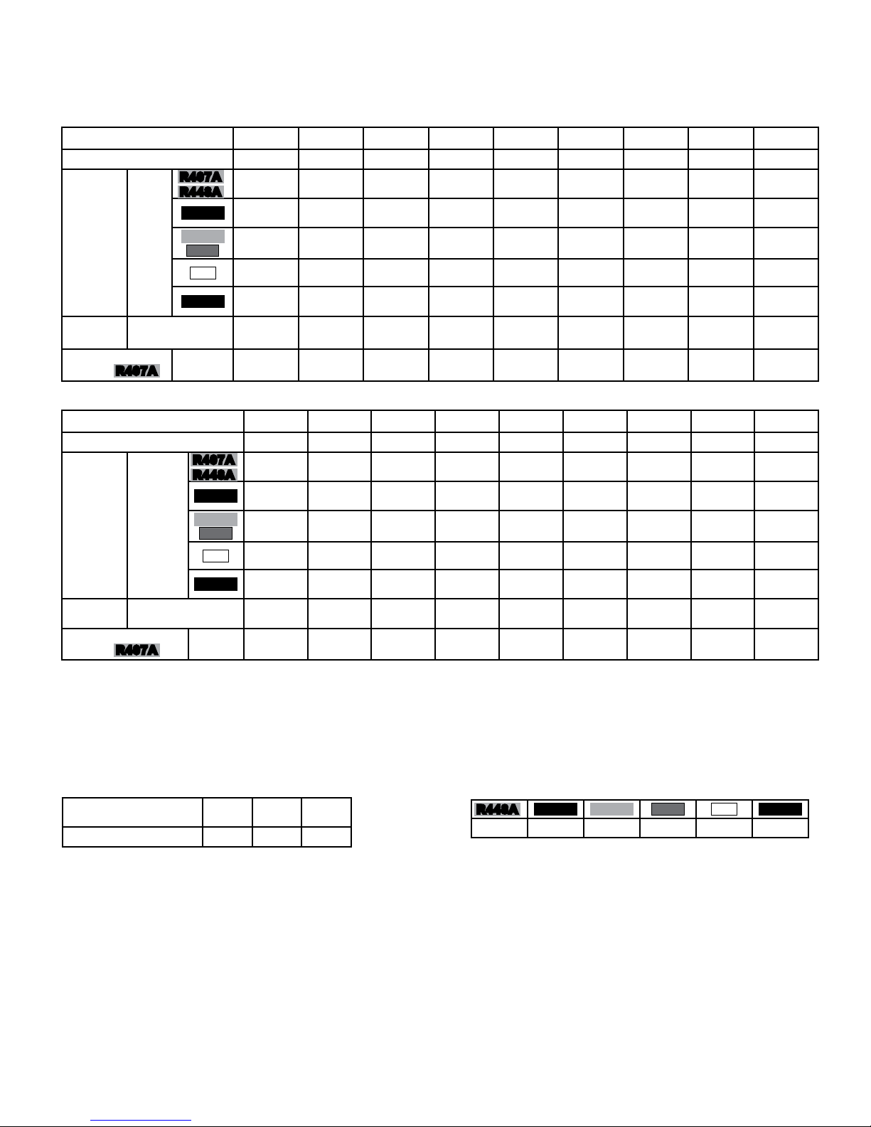
CAPACITY DATA - ALL MODELS
MEDIUM TEMPERATURE MODELS - CAPACITY *
Model TTL 010M 015M 020M 025M 032M 038M 060M 077M 115M
Number of Fans 1 1 1 1 1 1 2 2 3
900 1380 1900 2380 3040 3600 5700 7300 10900
(264) (404) (557) (696) (891) (1058) (1670) (2144) (3202)
860 1305 1800 2250 2880 3420 5400 6900 10400
(250) (383) (527) (660) (844) (1003) (1582) (2031) (3033)
950 1450 2000 2500 3200 3800 6000 7700 11500
(278) (425) (586) (733) (938) (1114) (1758) (2257) (3370)
900 1380 1900 2380 3000 3600 5700 7300 10900
(264) (404) (557) (696) (891) (1058) (1670) (2144) (3202)
855 1305 1800 2250 2880 3420 5400 6930 10350
(250) (383) (527) (660) (844) (1003) (1582) (2031) (3033)
130 180 237 270 440 440 928 807 1242
(61) (85) (112) (127) (208) (208) (438) (381) (586)
0.4 0.5 0.7 0.8 0.9 1.2 1.4 2.3 3.4
(0.2) (0.2) (0.3) (0.4) (0.4) (0.5) (0.6) (1.0) (1.5)
Capacity
BTUH
(WATTS)
Air Flow CFM (L/s)
Refrigerant **
Charge
Evap
Temp.
25°F
(-4°C)
R407A
R407A
R448A
R407C
R404A
R507
R22
R134a
Lbs (Kg)
LOW TEMPERATURE MODELS - CAPACITY *
Model TTL 009L 013L 017L 021L 028L 033L 052L 066L 099L
Number of Fans 1 1 1 1 1 1 2 2 3
810 1190 1620 2000 2660 3100 4900 6300 9400
(237) (348) (473) (584) (780) (919) (1448) (1837) (2756)
770 1125 1530 1890 2520 2970 4700 6000 8900
(224) (329) (448) (554) (739) (870) (1372) (1741) (2611)
850 1250 1700 2100 2800 3300 5200 6600 9900
(249) (366) (498) (615) (821) (967) (1524) (1934) (2901)
810 1190 1620 2000 2700 3100 4900 6300 9400
(237) (348) (473) (584) (780) (919) (1448) (1837) (2756)
765 1125 1530 1890 2520 2970 4680 5940 8910
(224) (329) (448) (554) (739) (870) (1372) (1741) (2611)
130 180 237 270 440 440 928 807 1242
(61) (85) (112) (127) (208) (208) (438) (381) (586)
0.4 0.5 0.7 0.8 0.9 1.2 1.4 2.3 3.4
(0.2) (0.2) (0.3) (0.4) (0.4) (0.5) (0.6) (1.0) (1.5)
Capacity
BTUH
(WATTS)
Air Flow CFM (L/s)
Refrigerant **
Charge
Evap
Temp.
-20°F
(-28.9°C)
R407A
R407A
R448A
R407C
R404A
R507
R22
R134a
Lbs
(Kg)
* Derate capacity by 5% when using EC Motors
Capacities rated using 10°F (5.6°C) TD & 100°F (38°C) liquid temperature.
Capacities at other TD within a range of 8 to 15 °F (4.4 to 8.3°C) are directly proportional to TD, or use formula: Capacity = Rated capacity ÷ 10 x TD.
For capacities at TD outside of range 8 to 15 °F (4.4 to 8.3°C), or liquid temperature lower than 75°F (24°), consult factory .
Capacities for R448A, R407A and R407C are based on mean temperature. Mean temperature is the average temperature between the saturated suction
temperature and the temperature feeding the evaporator. For dew point ratings, consult factory.
For R449A, use R448A data.
* CAPACITY CORRECTION FACTORS FOR LOW TEMPERATURE UNITS
SATURATED SUCTION
TEMPERATURE °F (°C)0 (-17.8)
FACTOR 1.06 1.03 1.0
NO CORRECTION FACTOR REQUIRED FOR MEDIUM TEMP. UNITS
-10
(23.3)
-20
(-28.9)
** REFRIGERANT CHARGE CONVERSION FACTORS
R448A
0.96 0.99 0.92 0.93 1.02 1.03
R407C R404A
R507
R22
R134a
Page 4
TTL 60Hz
23/06/17
T30-TTL-PDI-16
- 4 -
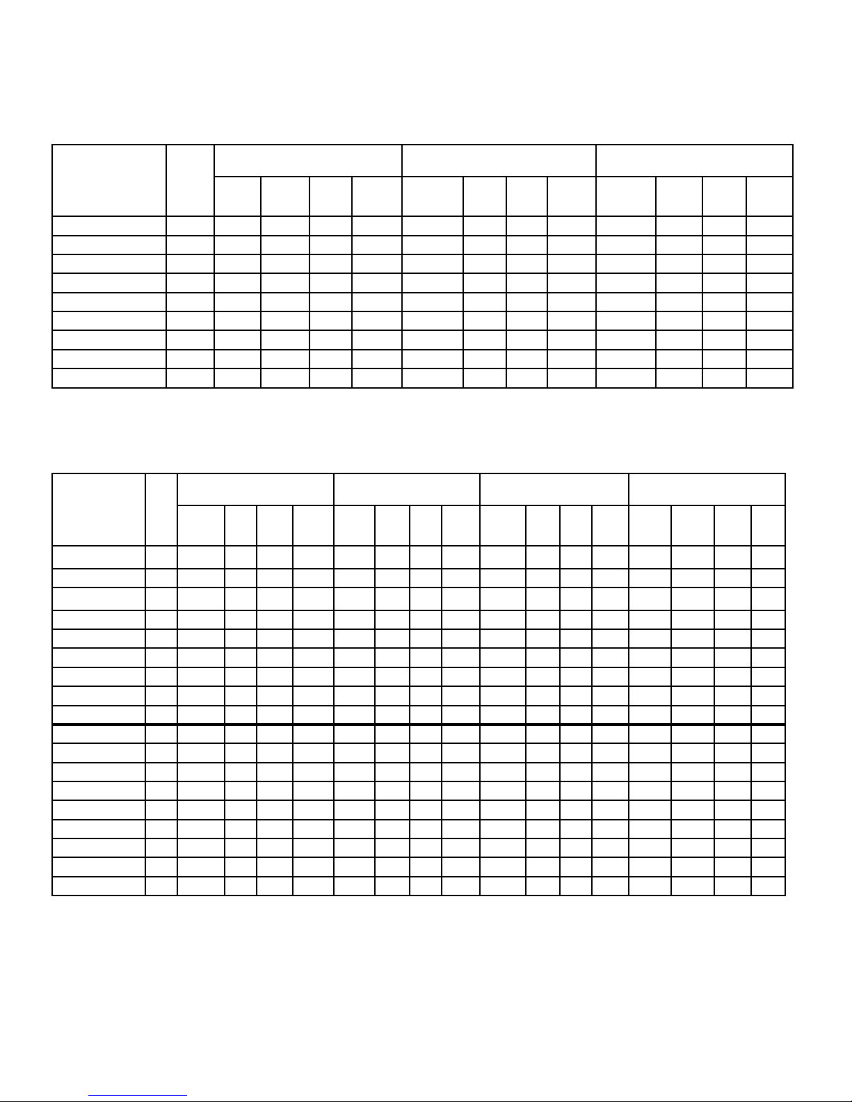
ELECTRICAL DATA
115/1/60
AIR DEFROST
MODEL
TTL
010MA-S1A 1 1.2 1.5 15 70 0.65 0.81 15 60 - - - -
015MA-S1A 1 1.2 1.5 15 70 0.65 0.81 15 60 - - - -
020MA-S1A 1 1.2 1.5 15 70 0.65 0.81 15 60 - - - -
025MA-S1A 1 1.2 1.5 15 70 0.65 0.81 15 60 - - - -
032MA-S1A 1 1.2 1.5 15 70 0.65 0.81 15 60 0.60 0.75 15 30
038MA-S1A 1 1.2 1.5 15 70 0.65 0.81 15 60 0.60 0.75 15 30
060MA-S1A 2 2.4 2.7 15 140 1.30 1.46 15 120 1.20 1.35 15 60
077MA-S1A 2 2.4 2.7 15 140 1.30 1.46 15 120 1.20 1.35 15 60
115MA-S1A 3 3.6 3.9 15 210 1.95 2.11 15 180 1.80 1.95 15 90
No.
of
FANS
TOTAL
MOTOR
FAN MOTOR(S) -
SHADED POLE (STANDARD)
M.C.A. M.O.P WATTS
FLA
MOTOR
ELECTRIC DEFROST
MODEL
TTL
010ME-S1A 1 1.2 1.5 15 70 0.65 0.81 15 60 - - - - 206 1.8 2.2 15
015ME-S1A 1 1.2 1.5 15 70 0.65 0.81 15 60 - - - - 530 4.6 5.8 15
020ME-S1A 1 1.2 1.5 15 70 0.65 0.81 15 60 - - - - 530 4.6 5.8 15
025ME-S1A 1 1.2 1.5 15 70 0.65 0.81 15 60 - - - - 530 4.6 5.8 15
032ME-S1A 1 1.2 1.5 15 70 0.65 0.81 15 60 0.60 0.75 15 30 750 6.5 8.2 15
038ME-S1A 1 1.2 1.5 15 70 0.65 0.81 15 60 0.60 0.75 15 30 750 6.5 8.2 15
060ME-S1A 2 2.4 2.7 15 140 1.30 1.46 15 120 1.20 1.35 15 60 1100 9.6 12.0 15
077ME-S1A 2 2.4 2.7 15 140 1.30 1.46 15 120 1.20 1.35 15 60 1540 13.4 16.8 20
115ME-S1A 3 3.6 3.9 15 210 1.95 2.11 15 180 1.80 1.95 15 90 2270 19.7 24.6 25
009LE-S1A 1 1.2 1.5 15 70 0.65 0.81 15 60 - - - - 206 1.8 2.2 15
013LE-S1A 1 1.2 1.5 15 70 0.65 0.81 15 60 - - - - 530 4.6 5.8 15
017LE-S1A 1 1.2 1.5 15 70 0.65 0.81 15 60 - - - - 530 4.6 5.8 15
021LE-S1A 1 1.2 1.5 15 70 0.65 0.81 15 60 - - - - 530 4.6 5.8 15
028LE-S1A 1 1.2 1.5 15 70 0.65 0.81 15 60 0.60 0.75 15 30 750 6.5 8.2 15
033LE-S1A 1 1.2 1.5 15 70 0.65 0.81 15 60 0.60 0.75 15 30 750 6.5 8.2 15
052LE-S1A 2 2.4 2.7 15 140 1.30 1.46 15 120 1.20 1.35 15 60 1100 9.6 12.0 15
066LE-S1A 2 2.4 2.7 15 140 1.30 1.46 15 120 1.20 1.35 15 60 1540 13.4 16.8 20
099LE-S1A 3 3.6 3.9 15 210 1.95 2.11 15 180 1.80 1.95 15 90 2270 19.7 24.6 25
No.
of
FANS
FAN MOTOR(S) -
SHADED POLE (STANDARD)
TOTAL
MOTOR
M.C.A. M.O.P WATTS
FLA
FAN MOTOR(S) PSC (OPTIONAL)
TOTAL
MOTOR
M.C.A. M.O.P WATTS
FLA
TOTAL
FLA
FAN MOTOR(S) PSC (OPTIONAL)
M.C.A. M.O.P WATTS
FAN MOTOR(S)-
EC (OPTIONAL)
TOTAL
MOTOR
M.C.A. M.O.P WATTS
FLA
TOTAL
MOTOR
FLA
TOTAL
WATTS
FAN MOTOR(S)-
EC (OPTIONAL)
M.C.A. M.O.P WATTS
DEFROST HEATERS
TOTAL
M.C.A. M.O.P
AMPS
Page 5
TTL 60Hz
23/06/17
T30-TTL-PDI-16
- 5 -
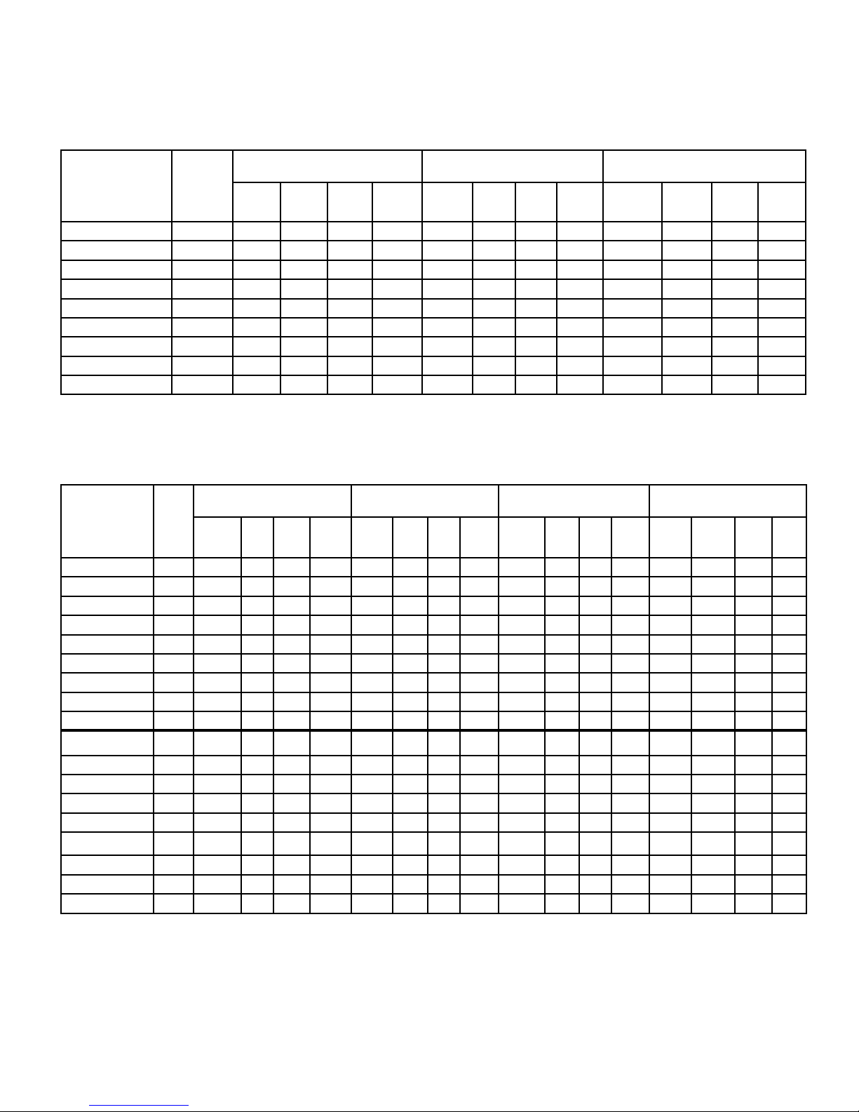
ELECTRICAL DATA
208-230/1/60
AIR DEFROST
TOTAL
MOTOR
FLA
FAN MOTOR(S) PSC (OPTIONAL)
M.C.A. M.O.P WATTS
TOTAL
MOTOR
MODEL
TTL
010MA-S2A 1 0.7 0.9 15 60 0.24 0.30 15 50 - - - -
015MA-S2A 1 0.7 0.9 15 60 0.24 0.30 15 50 - - - -
020MA-S2A 1 0.7 0.9 15 60 0.24 0.30 15 50 - - - -
025MA-S2A 1 0.7 0.9 15 60 0.24 0.30 15 50 - - - -
032MA-S2A 1 0.7 0.9 15 60 0.24 0.30 15 50 0.30 0.40 15 30
038MA-S2A 1 0.7 0.9 15 60 0.24 0.30 15 50 0.30 0.40 15 30
060MA-S2A 2 1.4 1.6 15 120 0.48 0.54 15 100 0.60 0.70 15 60
077MA-S2A 2 1.4 1.6 15 120 0.48 0.54 15 100 0.60 0.70 15 60
115MA-S2A 3 2.1 2.3 15 180 0.72 0.78 15 150 0.90 1.00 15 90
No.
of
FANS
TOTAL
MOTOR
FAN MOTOR(S) -
SHADED POLE
M.C.A. M.O.P WATTS
FLA
(STANDARD)
ELECTRIC DEFROST
FAN MOTOR(S)-
EC (OPTIONAL)
M.C.A. M.O.P WATTS
FLA
MODEL
TTL
010ME-S2A 1 0.7 0.9 15 60 0.24 0.30 15 50 - - - - 206 0.9 1.1 15
015ME-S2A 1 0.7 0.9 15 60 0.24 0.30 15 50 - - - - 530 2.3 2.9 15
020ME-S2A 1 0.7 0.9 15 60 0.24 0.30 15 50 - - - - 530 2.3 2.9 15
025ME-S2A 1 0.7 0.9 15 60 0.24 0.30 15 50 - - - - 530 2.3 2.9 15
032ME-S2A 1 0.7 0.9 15 60 0.24 0.30 15 50 0.30 0.40 15 30 750 3.3 4.1 15
038ME-S2A 1 0.7 0.9 15 60 0.24 0.30 15 50 0.30 0.40 15 30 750 3.3 4.1 15
060ME-S2A 2 1.4 1.6 15 120 0.48 0.54 15 100 0.60 0.70 15 60 1100 4.8 6.0 15
077ME-S2A 2 1.4 1.6 15 120 0.48 0.54 15 100 0.60 0.70 15 60 1540 6.7 8.4 15
115ME-S2A 3 2.1 2.3 15 180 0.72 0.78 15 150 0.90 1.00 15 90 2270 9.9 12.4 15
009LE-S2A 1 0.7 0.9 15 60 0.24 0.30 15 50 - - - - 206 0.9 1.1 15
013LE-S2A 1 0.7 0.9 15 60 0.24 0.30 15 50 - - - - 530 2.3 2.9 15
017LE-S2A 1 0.7 0.9 15 60 0.24 0.30 15 50 - - - - 530 2.3 2.9 15
021LE-S2A 1 0.7 0.9 15 60 0.24 0.30 15 50 - - - - 530 2.3 2.9 15
028LE-S2A 1 0.7 0.9 15 60 0.24 0.30 15 50 0.30 0.40 15 30 750 3.3 4.1 15
033LE-S2A 1 0.7 0.9 15 60 0.24 0.30 15 50 0.30 0.40 15 30 750 3.3 4.1 15
052LE-S2A 2 1.4 1.6 15 120 0.48 0.54 15 100 0.60 0.70 15 60 1100 4.8 6.0 15
066LE-S2A 2 1.4 1.6 15 120 0.48 0.54 15 100 0.60 0.70 15 60 1540 6.7 8.4 15
099LE-S2A 3 2.1 2.3 15 180 0.72 0.78 15 150 0.90 1.00 15 90 2270 9.9 12.4 15
No. of
FANS
FAN MOTOR(S) -
SHADED POLE(STANDARD)
TOTAL
MOTOR
M.C.A. M.O.P WATTS
FLA
FAN MOTOR(S) PSC (OPTIONAL)
TOTAL
MOTOR
M.C.A. M.O.P WATTS
FLA
FAN MOTOR(S)-
EC (OPTIONAL)
TOTAL
MOTOR
M.C.A. M.O.P WATTS
FLA
DEFROST HEATERS
TOTAL
WATTS
TOTAL
AMPS
M.C.A. M.O.P
Page 6

1-TL AD 03/08
TERMINAL BOARD
PUMP DOWN
WIRED ON EVAPORATOR .
2). USE 75°C WIRE (OR HIGHER)
EVAPORATOR FAN MOTORS AND DEFROST
HEATERS MUST NOT EXCEED MAXIMUM
VALUE SHOWN ON EVAPORATOR NAMEPLATE.
1). USE COPPER CONDUCTORS ONLY
3). OVERCURRENT PROTECTION FOR
4). MAY BE FACTORY INSTALLED-MOUNTED AND
NOTES
MTR
FAN
MTR
FAN
4
GND.
F
(IF USED)
SWITCH
CONDUCTORS/WIRING
FACTORY WIRING
WIRING BY OTHERS
BY OTHERS
OPTIONAL FACTORY OR
COMPLIANCE WITH ALL APPLICABLE LOCAL
ALL FIELD WIRING MUST BE DONE IN
AND NATIONAL CODES.
TERMINAL BOARD
NOTE #4
SPACE
THERMOSTAT
-COMPONENT TERMINAL
-TERMINAL BLOCK TERMINAL
FAN MOTOR
POWER
PLUGS
REFER TO
EVAPORATOR
DATA PLATE
FOR MOTOR
QUANTITY
MTR
FAN
TERMINALS
MTR
FAN
MTR
FAN
SOLENOID VALVE
EVAPORATOR
NOTE #4
SPACE
THERMOSTAT
N.C.
NOTE #4
LIQUID LINE
4
GND.
F
FAN MOTOR
POWER
PLUGS
REFER TO
EVAPORATOR
DATA PLATE
FOR MOTOR
QUANTITY
MTR
FAN
EVAPORATOR
N.C.
NOTE #4
LIQUID LINE
SOLENOID VALVE
WITH DEFROST TIME CLOCK
GND
132
4NX
TM
OR EQUIVALENT
DEFROST CLOCK
PARAGON # 8145
EVAPORATORS (IF APPLIC)
NAMEPLATE FOR ELECTRICAL
REFER TO EVAPORATOR
WITHOUT DEFROST TIME CLOCK
GND
IF(N)
TO MULTIPLE EVAPS
F
4
(IF APPLIC)
OMIT 2ND
BREAKER
NOTE #3
FUSE OR
FUSE
CIRCUIT
4
F
BREAKER
NOTE #3
CIRCUIT
FUSE OR
NAMEPLATE FOR ELECTRICAL
REFER TO EVAPORATOR
REQUIREMENTS
L2(N)
L1
REQUIREMENTS
GND
L1
L2(N)
TO MULTIPLE
IF(N)
2ND FUSE
OMIT
(SUPPLIED ON MULTIPLE
FAN MODELS ONLY)
(SUPPLIED ON MULTIPLE
FAN MODELS ONLY)
TTL 60Hz
23/06/17
T30-TTL-PDI-16
- 6 -
WIRING DIAGRAM
AIR DEFROST - ALL VOLTAGES
Page 7

FAN
MTR
FAN
MTR
FAN
MTR
DATA PLATE FOR
MOTOR QUANTITY
EVAPORATOR
REFER TO
EVAPORATOR
FAN MOTOR
POWER PLUGS
RD
DEFROST TERMINATION
FD-FAN DELAY
DT-DEFROST TERM
& FAN DELAY
(10.0A MAX.)
CONTROL
FD
BK
FAN MOTOR
POWER PLUGS
REFER TO
DATA PLATE FOR
MOTOR QUANTITY
EVAPORATOR
MTRMTRMTR
FANFAN FAN
(10.0A MAX.)
DT-DEFROST TERM
FD-FAN DELAY
& FAN DELAY
CONTROL
DEFROST TERMINATION
FD
BK
EVAPORATOR
PARAGON # 8145
MUST BE MADE
EVAP FIELD MODIFICATION
WARNING
SEE NOTE:
SPACE
GND.
F
4
DT
BN
C
X
3
N
H1
H3H2
ORANGE JUMPER
THERMOSTAT
NOTE #4
SWITCH
(IF USED)
PUMP DOWN
NOTE #4
SOL VALVE
1
N.C.
LIQUID LINE
BREAKER
(IF USED)
COMPR INTERLOCK
12
N
NAMEPLATE FOR ELECTRICAL
REFER TO EVAPORATOR
GND
REQUIREMENTS
3
4
TM
X
FUSE OR
CIRCUIT
PARAGON # 8145
DEFROST CLOCK
OR EQUIVALENT
15A
N
L1
N.C.
LIQUID LINE
SOL VALVE
NOTE #4
GND.
3
N
X
4
F
DT
BN
RD
C
FROM H2 TO N
REMOVE ORANGE JUMPER
(IF USED)
SWITCH
PUMP DOWN
NOTE #4
H2
H3
H1
SPACE
THERMOSTAT
(IF USED)
COMPR INTERLOCK
OR EQUIVALENT
1
CIRCUIT
4
2
3
X
N
NOTE #3
BREAKER
TM
FUSE OR
DEFROST HEATER
L1
C
T1
CONTACTOR
CIRCUIT
BREAKER
NOTE #3
N
GND
L1
FUSE OR
USING MAXIMUM 15A HEATER OVERCURRENT PROTECTION
FOR ALL MODELS WITHOUT DEFROST HEATER CONTACTOR
FOR ALL MODELS USING DEFROST HEATER CONTACTOR
REFER TO EVAPORATOR
DEFROST CLOCK
REQUIREMENTS
NAMEPLATE FOR ELECTRICAL
FAN MODELS ONLY)
(SUPPLIED ON MULTIPLE
TERMINAL BOARD
BK
BK
DEFROST HEATERS
BOTTOM
BK
BOTTOM
L.H. COIL
BK
R.H. COIL
ORANGE
JUMPER
DEFROST HEATERS
L.H. COIL
BOTTOM
BK
R.H. COIL
BOTTOM
BK
BK
BK
ORANGE
JUMPER
T2
L2
ORANGE JUMPER
1
SEE NOTE:
TERMINAL BOARD
(SUPPLIED ON MULTIPLE
FAN MODELS ONLY)
DEFROST HEATERS MUST NOT EXCEED
4.) MAY BE FACTORY INSTALLED-MOUNTED
MAXIMUM VALUE SHOWN ON
EVAPORATOR NAMEPLATE.
EVAPORATOR FAN MOTORS AND
AND WIRED ON EVAPORATOR
1). USE COPPER CONDUCTORS ONLY
3). OVERCURRENT PROTECTION FOR
2). USE 75°C WIRE (OR HIGHER)
NOTES
FACTORY WIRING
OPTIONAL FACTORY
WIRING BY OTHERS
OR BY OTHERS
ALL FIELD WIRING MUST BE DONE IN
COMPLIANCE WITH ALL APPLICABLE LOCAL
AND NATIONAL CODES.
TERMINALS
-TERMINAL BLOCK TERMINAL
-COMPONENT TERMINAL
CONDUCTORS/WIRING
2-TL ED1 03/08
(IF APPLIC.)
TTL 60Hz
23/06/17
T30-TTL-PDI-16
- 7 -
WIRING DIAGRAM
ELECTRIC DEFROST - 115V
Page 8

TTL 60Hz
23/06/17
T30-TTL-PDI-16
- 8 -
WIRING DIAGRAM
ELECTRIC DEFROST - 230V
Page 9

BOTTOM VIEW
Connection
CONNECTION END VIEW
TXV
Connection
AIR
OUT
AIR IN
with electric defrost heaters
splice box and defrost control
NOTE: Dimensional views shown
Suction
OUT
AIR
mounted.
7/8 (22 mm) dia.
2 each side
9/16 (14 mm) dia.
2 each side
1/2 (12 mm) dia.
aluminum drain.
2 connection end
7/8 (22 mm) dia.
knockouts
knockouts
knockouts
SIDE VIEW
PIPING CONNECTION
1-3/8"
(35 mm)
3"
(76 mm)
9/16"
(14 mm)
Splice box.
electric defrost models
Defrost control
4 Mounting holes
7/32 (6 mm) dia.
E
D
B
A
C
TTL 60Hz
23/06/17
T30-TTL-PDI-16
- 9 -
DIMENSIONAL DATA - 1 FAN
Inches (mm)
MODEL
TTL
010M* 3/8 1/2” Flare 18 7/8 479 4 1/2 114 14 1/8 359 17 3/4 451 9 3/4 248 11.6 5.3
015M* 3/8 1/2” Flare 18 7/8 479 4 1/2 114 14 1/8 359 17 3/4 451 9 3/4 248 12.6 5.7
Suc. Conn. TXV A B C D E
(ID) Sweat Inlet Size Inches mm Inches mm Inches mm Inches mm Inches mm Lbs. Kgs
020M* 3/8 1/2” Flare 18 7/8 479 5 1/2 140 14 1/8 359 17 3/4 451 9 3/4 248 13.7 6.2
025M* 3/8 1/2” Flare 18 7/8 479 5 1/2 140 14 1/8 359 17 3/4 451 9 3/4 248 14.7 6.7
032M* 3/8 1/2” ODS 21 7/8 556 5 1/2 140 19 1/8 486 20 3/4 527 14 3/4 375 18.9 8.6
038M* 3/8 1/2” ODS 21 7/8 556 5 1/2 140 19 1/8 486 20 3/4 527 14 3/4 375 20.0 9.1
009LE 3/8 1/2” Flare 18 7/8 479 4 1/2 114 14 1/8 359 17 3/4 451 9 3/4 248 11.6 5.3
013LE 3/8 1/2” Flare 18 7/8 479 4 1/2 114 14 1/8 359 17 3/4 451 9 3/4 248 12.6 5.7
017LE 3/8 1/2” ODS 18 7/8 479 5 1/2 140 14 1/8 359 17 3/4 451 9 3/4 248 13.7 6.2
021LE 3/8 1/2” ODS 18 7/8 479 5 1/2 140 14 1/8 359 17 3/4 451 9 3/4 248 14.7 6.7
028LE 1/2 1/2” ODS 21 7/8 556 5 1/2 140 19 1/8 486 20 3/4 527 14 3/4 375 18.9 8.6
033LE 1/2 1/2” ODS 21 7/8 556 5 1/2 140 19 1/8 486 20 3/4 527 14 3/4 375 20.0 9.1
* - A (AIR DEFROST) OR E (ELECTRIC DEFROST)
APPROX.
WEIGHT
Page 10

compartment
Electrical
OUT
AIR
AIR
PIPING CONNECTION
END VIEW
AIR IN
2 each side
knockouts
7/8 (22 mm) dia
knockouts
9/16 (14 mm) dia
2 each side
2). Electrical connection end is
opposite the piping end on
NOTES: 1). Electric defrost views shown.
Air defrost models have identical
BOTTOM VIEW
AIR
SIDE VIEW
AIR
OUT
1-1/8 (28 mm) dia
knockouts
1 each side
1" FPT. Aluminum
drain fitting.
dimensioning.
multiple fan models.
1 each side
knockouts
7/8 (22 mm) dia
TXV Connection 1/2"(13) ODS.
33
5/16 (9 mm)
Mounting holes.
22-1/4
(565)
ED F
23-5/8
(600)
C
7-5/8
(194)
23-3/4 (603)
23/06/17
T30-TTL-PDI-16
- 10 -
TTL 60Hz
DIMENSIONAL DATA - 2 & 3 FAN
Inches (mm)
3/4” MPT / 3/4 are
drain connection
MODEL
TTL
Suc. Conn. TXV C D E F APPROX. WEIGHT
(ID) Sweat Inlet Size Inches mm Inches mm Inches mm Inches mm Lbs. Kgs
060M 1/2 1/2” ODS 42 3/4 1086 4 holes @ 8” 203 7 11/16 195 10 15/16 278 37.8 17.1
077M 5/8 1/2” ODS 42 3/4 1086 4 holes @ 8” 203 7 11/16 195 10 15/16 278 39.9 18.1
115M 5/8 1/2” ODS 59 1/2 1511 6 holes @ 8” 203 8 203 11 7/16 291 59.9 27.2
052LE 5/8 1/2” ODS 42 3/4 1086 4 holes @ 8” 203 7 11/16 195 10 15/16 278 37.8 17.1
066LE 5/8 1/2” ODS 42 3/4 1086 4 holes @ 8” 203 7 11/16 195 10 15/16 278 39.9 18.1
099LE 7/8 1/2” ODS 59 1/2 1511 6 holes @ 8” 203 8 203 11 7/16 291 59.9 27.2
Page 11

TTL 60Hz
23/06/17
T30-TTL-PDI-16
- 11 -
NOZZLE SELECTIONS
(FACTORY INSTALLED)
For all applications and refrigerants
Model TTL Nozzle
010MA/ME NA
015MA/ME NA
020MA/ME NA
025MA/ME NA
032MA/ME L-1/4
038MA/ME L-1/3
060MA/ME L-1/2
077MA/ME L-3/4
115MA/ME L-1
Model TTL Nozzle
009LE NA
013LE NA
017LE L-1/4
021LE L-1/3
028LE L-1/2
033LE L-1/2
052LE L-1
066LE L-1
099LE L-1 1/2
RECOMMENDED EXPANSION VALVE SELECTION
MEDIUM TEMPERATURE MODELS
SPORLAN
MODEL
TTL
010M
015M
020M
025M
032M
038M
060M
077M
115M
For medium temp. R-507, refrigerant designation changes from ‘S’ to ‘P’.
For R449A, use R448A data.
TD
10
15
10
15
10 EGS-1/6-C EGV-1/5-C
15 EGS-1/6-C EGV-1/3-C
10
15 EGV-1/3-C
10
15 SBFVE-AA-C
10 SBFSE-AA-C SBFVE-AAA-C
15 SBFSE-A-C SBFVE-AA-C
10
15
10
15 SBFVE-A-C
10 SBFSE-A-C
15 SBFSE-B-C
R404A
R507
EGS-1/8-C EGV-1/5-C
EGS-1/6-C EGV-1/5-C
EGS-1/6-C
SBFSE-AA-C
SBFSE-A-C SBFVE-AA-C
SBFSE-A-C
R448A
R407A
R407C
EGV-1/5-C
SBFVE-AAA-C
SBFVE-AA-C
SBFVE-A-C
R22
ALCO
ALL TXV Selections based on 90-100°F liquid.
For R449A, use R448A data.
DANFOSS
MODEL
TTL
010M
015M
020M
025M
032M
038M
060M
077M
115M
For R449A, use R448A data.
TD
10 TUA-R404A-0-N
15 TUA-R404A-1-N
10 TUA-R404A-1-N TUA-R22-0-N
15 TUA-R404A-2-N TUA-R22-1-N
10 TUA-R404A-2-N TUA-R22-1-N
15 TUAE-R404A-3-N TUAE-R22-2-N
10 TUA-R404A-2-N TUA-R22-1-N
15 TUAE-R404A-3-N TUAE-R22-2-N
10 TUAE-R404A-3-N TUAE-R22-2-N
15 TUAE-R404A-4-N TUAE-R22-3-N
10 TUAE-R404A-3-N TUAE-R22-3-N
15 TUAE-R404A-4-N TUAE-R22-4-N
10 TUAE-R404A-5-N TUAE-R22-4-N
15 TUAE-R404A-6-N TUAE-R22-5-N
10 TUAE-R404A-5-N TUAE-R22-5-N
15 TUAE-R404A-6-N TUAE-R22-6-N
10 TUAE-R404A-6-N TUAE-R22-6-N
15 TUAE-R404A-8-N TUAE-R22-7-N
R404A
R507
R448A
R407C
TUA-R22-0-N
R407A
R22
MODEL
TTL
010M
015M
020M
025M
032M
038M
060M
077M
115M
TD
10
15
10
15
10 HF-1/8-SC
15 HF-1/4-SC
10
15
10 HFESC-1/4-SC HFESC-1/4-HC
15 HFESC-1/2-SC HFESC-1/2-HC
10 HFESC-1/4-SC
15 HFESC-1/2-SC
10 HFESC-1/2-SC HFESC-1/2-HC
15 HFESC-1-SC HFESC-1-HC
10 HFESC-1/2-SC
15 HFESC-1-SC
10 HFESC-1-SC HFESC-1-HC
15 HFESC-1 1/4-SC HFESC-1 1/2-HC
R404A
R507
HF-1/8-SC HF-1/4-HC
HF-1/8-SC HF-1/4-HC
HF-1/4-SC HF-1/4-HC
R448A
HFESC-1/2-HC
R407A
R407C
HFESC-1-HC
R22
HF-1/4-HC
Page 12

TTL 60Hz
23/06/17
T30-TTL-PDI-16
- 12 -
RECOMMENDED EXPANSION VALVE
SELECTION -
MEDIUM TEMPERATURE MODELS
SPORLAN -
MODEL
TTL
0 865 EGV-1/5-C 1,273 EGV-1/5-C 1,729 EGVE-1/5-C 2,138 SBFVE-AAA-C 2,850 SBFVE-AAA-C
EVAP
TEMP.
EVAP
TEMP.
°F
Selections based on 90-100°F liquid.
For R407A valves operating below 0F, the pressure limiting charge ‘ZP40’ may be substituted for the ‘Z’ charge.
R407A derated by .95 factor
For R449A, use R448A data.
-10 836
-15 827 1,216 1,644 2,033 2,717
°F
-20 808 1,188 1,615 1,995 2,660
MODEL
TTL
0 3,354 SBFVE-AAA-C 5,282 SBFVE-AA-C 6,707 SBFVE-AA-C 10,061 SBFVE-A-C
-10 3,259
-20 3,135 4,940 6,270 9,405
SPORLAN -
MODEL
TTL
0 910 EGS-1/8-C 1,340 EGS-1/8-C 1,820 SBFSE-AAA-C 2,250 SBFSE-AAA-C 3,000 SBFSE-AA-C
EVAP
TEMP.
EVAP
TEMP.
°F
-10 880
-15 870 1,280 1,730 2,140 2,860
°F
-20 850 1,250 1,700 2,100 2,800
MODEL
TTL
0 3,530 SBFSE-AA-C 5,560 SBFSE-AA-C 7,060 SBFSE-A-C 10,590 SBFSE-A-C
-10 3,430
-20 3,300 5,200 6,600 9,900
R407A
009L 013L 017L 021L 028L
BTUH VALVE # BTUH VALVE # BTUH VALVE # BTUH VALVE # BTUH VALVE #
EGV-1/5-Z
033L 052L 066L 099L
BTUH VALVE # BTUH VALVE BTUH VALVE # BTUH VALVE #
SBFVE-AA-Z
R404A
009L 013L 017L 021L 028L
BTUH VALVE # BTUH VALVE # BTUH VALVE # BTUH VALVE # BTUH VALVE #
EGS-1/8-Z
033L 052L 066L 099L
BTUH VALVE # BTUH VALVE BTUH VALVE # BTUH VALVE #
SBFSE-AA-Z
R448A
1,235
5,140
1,300
5,410
EGV-1/5-Z
SBFVE-AA-Z
EGS-1/8-Z
SBFSE-A-Z
1,682
6,517
1,770
6,860
SBFVE-AAA-Z
SBFVE-AA-Z
SBFSE-AAA-Z
SBFSE-A-Z
2,071
SBFVE-AAA-Z
9,785
2,180
SBFSE-AAA-Z
10,300
2,765
SBFVE-AAA-Z
SBFVE-A-Z-15 3,202 5,035 6,394 9,595
2,910
SBFSE-AA-Z
SBFSE-A-Z-15 3,370 5,300 6,730 10,100
Selections based on 90-100°F liquid.
For medium temp. R-507, refrigerant designation changes from ‘S’ to ‘P’.
For R404A/R507 valves operating below 0F, the pressure limiting charge ‘ZP’ may be substituted for the ‘Z’ charge.
For R449A, use R448A data.
Page 13

TTL 60Hz
23/06/17
T30-TTL-PDI-16
- 13 -
INSTALLATION INSTRUCTIONS
INSPECTION
Careful inspection of all parts when received for loss
or damage in transit is very important Remember, you, the consignee, must make any
claim necessary against the transportation company.
Shipping damage or missing parts, when discovered
at the outset, will prevent later unnecessary and
costly delays.
Electrical characteristics should also be checked at
this time to ensure that they are as ordered.
APPLICATION
Two-Way evaporators are designed for use in coolers and freezers such as reach in boxes, display
cases, back bars, walk-in rooms and any other
cooler applications where a low velocity, uniform air
ow is required. The compact and low height unit
provides maximum useable product storage space.
o
At room temperatures above 34°F (1.1
C) and evap-
orating temperatures no lower than 27°F (-2.8°C)
the air owing through the coil will accomplish the
defrost (Air Defrost).
o
At room temperatures 34
F and below (to -10oF)
positive defrosting is required (Electric defrost).
These will require the use of:
1. Time Clock (to initiate and terminate the defrost
cycle),
2. Defrost termination thermostat (to prevent
unnecessary prolonged heating and steaming of the
coil once all the frost and ice has melted). And if a
freezer,
3. Fan delay thermostat (to prevent evaporator fans
starting up right away and blowing water on to the
fan blades, guards and oor).
This evaporator coil must not be exposed to any
abnormal environments (acidic or caustic) that can
result in coil corrosion and leaks. Consult factory
for optional baked on phenolic protective coatings.
These evaporators are for use primarily on R448A/
R407A/R407C/R404A/R507/R22 and R134a refrigerants and their approved alternatives / replace-
ments.
INSTALLATION
The installation and start up of evaporators should
only be performed by qualied refrigeration
mechanics. This equipment should be installed in
accordance with all applicable codes, ordinances,
and local by-laws.
LOCATION
The evaporator is designed to be mounted to the
ceiling of the box or cabinet. Refrigeration piping and
electrical connections are routed to the rear sides
(through the knock-outs). The unit must be mounted
to a level ceiling to ensure complete drainage from
the condensate pan to the drain tting. Refer to the
dimensional drawings for the drain tting and
mounting location details.
On freezer applications it is important that warm, hu-
mid inltrated air is not drawn directly towards the
evaporator. Keeping the evaporator away from the
door, using strip curtains, and using door switches
to lock out and de-energize the liquid solenoid valve
are all eective methods to minimize any unnecessary frost build -up of the fan guard. (Air enters the
fan and discharges out each side of the coil).
TXV SELECTION (thermostatic expansion valve)
For normal operating conditions refer to the TXV
selection chart. When selecting valves ensure they
are sized to meet the capacity at the actual evaporating temperature, liquid temperature and operating
TD of the system . All these conditions can greatly
aect the size and selection. Consult the factory or
valve manufacturer for assistance. All models that
use a distributor (larger models) must use a nozzle.
Smaller models do not have distributors or nozzles.
The TXV superheat setting should NOT be initially
adjusted . After the room has reached or is close to
the required operating temperature the TXV superheat should then be checked and only adjusted if
necessary. Refer to Section on SYSTEM CHECK.
To avoid overheating the valve or distributor
wrap a wet cloth around the valve diaphragm
and body.
MOUNTING
Mounting brackets with 7/32 - 5/16” diameter holes
are provided for ush mounting to the ceiling.
Ensure the evaporator is located correctly with
the air owing in the two desired directions. Avoid
discharging the air directly on to glass doors or door
openings.
After mounting the coil check the slope of the drain
pan with a level. If the ceiling is not level the drain
pan slope may not be correct which can result in
defrosting (ice-up) problems.
Page 14

TTL 60Hz
23/06/17
T30-TTL-PDI-16
- 14 -
INSTALLATION INSTRUCTIONS (CONT’D)
DRAIN LINE
The drain line should be run from the drain
connection, sloping at least 4” vertical drop for
every foot of horizontal distance . A trap outside
the room will allow proper draining throughout the
line. Connection should be made to proper drainage
facilities that comply with local codes and regulations.
In freezers, to prevent drain line freeze up problems, the line must be heated and insulated. A heat
input of 20 W per foot in a 0°F room and 30 W
per foot in a -20°F room is usually satisfactory.
Once the line has been completed , double check
the slope in the drain pan to ensure proper drainage
(prevention of ice build-up on pan).
PIPING
Refrigerant line sizes are important and are not
necessarily the same size as the connections at the
condensing unit or evaporator. If in doubt refer to
a recognized source. (Manufacturer’s Engineering
Manual, Ashrae Manuals, etc.)
WIRING
Wire system in accordance with local codes and
regulations. A 36” cord is provided for single fan air
defrost models (AD). Multiple fans have a junction
terminal box for conduit connections.
When fan delay thermostats are installed the fans
may not start up until the coil temperature
reaches approximately 26°F. On initial start up it may
be necessary to bypass (jumper) this control
temporarily until the coil is cold enough.
SYSTEM CHECK
Before Start Up:
1. Ensure wiring is in accordance with codes.
2. Refrigerant lines are properly sized and routed.
3. Thorough leak check, evacuation and dehydration
has been performed.
4. Drain line has been checked for free ow.
After Start Up:
1. Fan has been checked for correct air ow and no
obstructions.
2. Expansion valve superheat has been checked for
proper operation. (Superheat of the coil should be
around 5 to 6°F for a 10°F TD.)
MAINTENANCE
The unit should be periodically inspected for any dirt
or build up on the n surface and cleaned if
necessary with a soft whisk or brush.
The fan motor is permanently lubricated and should
not require service.
PROJECT INFORMATION
System
Model Number Date of Start-Up
Serial Number Service Contractor
Refrigerant Phone
Electrical Supply E-Mail
Page 15

TTL 60Hz
23/06/17
T30-TTL-PDI-16
- 15 -
PRODUCT SUPPORT RESOURCES
web: t-rp.com/ttl
email: evaps@t-rp.com
call: 1-844-893-3222 x520
email: troubleshooting@t-rp.com
call: 1-844-893-3222 x529
web: t-rp.com/parts
email: parts@t-rp.com
call: 1-844-893-3222 x501
web: t-rp.com/warranty
email: warranty@t-rp.com
call: 1-844-893-3222 ext. 501
email: orders@t-rp.com
call: 1-844-893-3222 x501
email: shipping@t-rp.com
call: 1-844-893-3222 x503
Page 16

“AS BUILT” SERVICE PARTS LIST
23/06/17
Service Parts List
Label
To Be Attached
HERE
NATIONAL REFRIGERATION &
AIR CONDITIONING CANADA CORP.
159 Roy Blvd.
Brantford Ontario Canada N3R 7K1
PHONE: (519) 751-0444 800-463-9517
FAX (519) 753-1140 www.t-rp.com
Due to the manufacturer’s policy of continuous product improvement, we reserve the right to make changes without notice.
 Loading...