

Trenton TPLP104MAS1, TPLP209MAS1, TPLP107MAS1, TPLP106MAS1, TPLP211MAS1 Installation Instructions Manual
...Page 1
PRODUCT DATA &
29/11/18
INSTALLATION
Bulletin T30-TPLP-PDI-14
Part #1087152
PRODUCT SUPPORT
web: t-rp.com/tplp
email: evaps@t-rp.com
call: 1-844-893-3222 x520
scan:
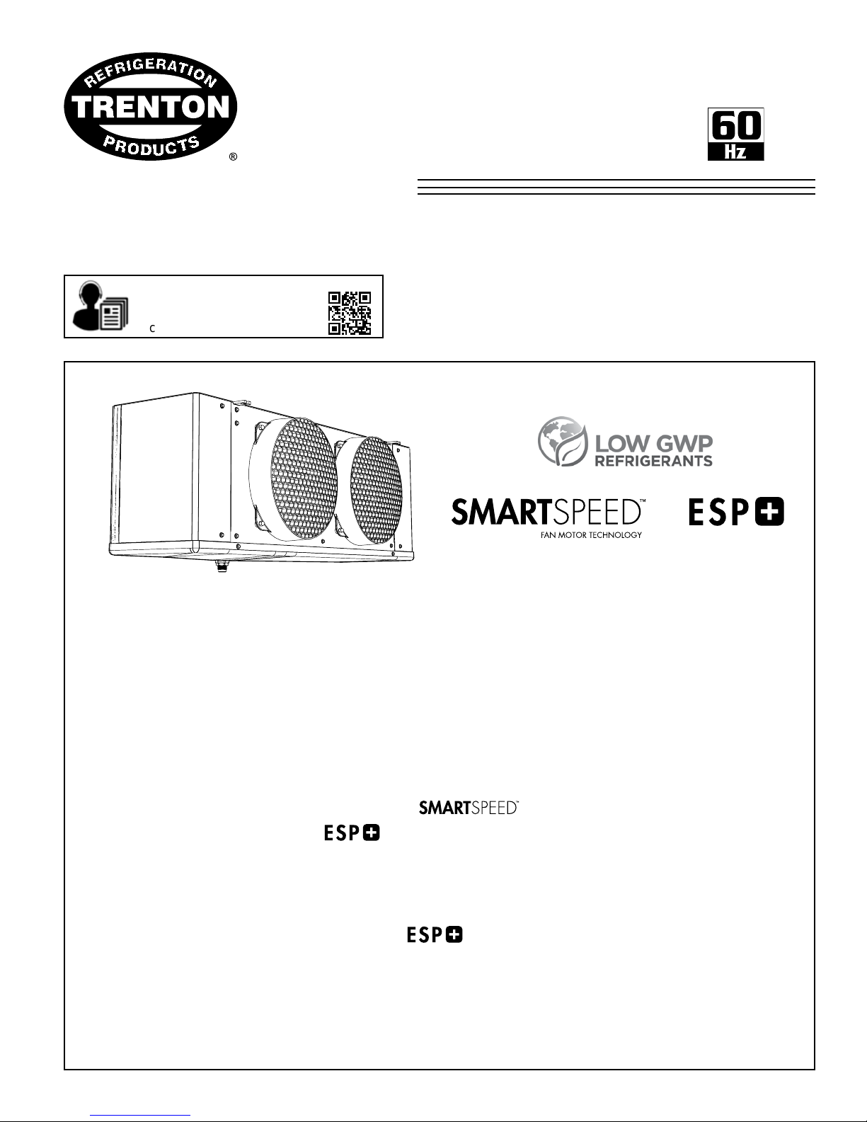
TPLP Pre-Assembled
Low Prole
Evaporators
Air & Electric Defrost
Medium T emperature Applications: 35°F
Low T emperature Applications: -10°F
Electrical: 115/1/60, 208-230/1/60, 208-230/3/60, 460/1/60
See Page 16 for details
see page 20 for details
CONTENTS
Page
Nomenclature................................................................................................................. 2
Standard Features (All Models)...................................................................................... 2
Available Congurations................................................................................................. 3
Capacity Data................................................................................................................. 4
Electrical Data................................................................................................................. 5 - 7
Wiring Diagrams - Models with PSC motors .................................................................. 8 - 15
Wiring Diagrams - Models with EC Motors / ............................................ 16 - 19
Wiring Diagrams - Models with ......................................................................... 20 - 25
Shipping Weights............................................................................................................ 26
Dimensional Data............................................................................................................ 27
Expansion Valve Selections - Electro-Mechanical Models............................................. 28 - 29
Expansion Valve Selections - Models with ....................................................... 30
Installation Instructions................................................................................................... 31 -32
Project Information........................................................................................................... 34
Product Support Resources: Service Parts, Troubleshooting, Warranty, etc................... 35
“As Built” Service Parts.................................................................................................... Back
Page 2
NOMENCLATURE
29/11/18
T30-TPLP-PDI-14
- 2 -
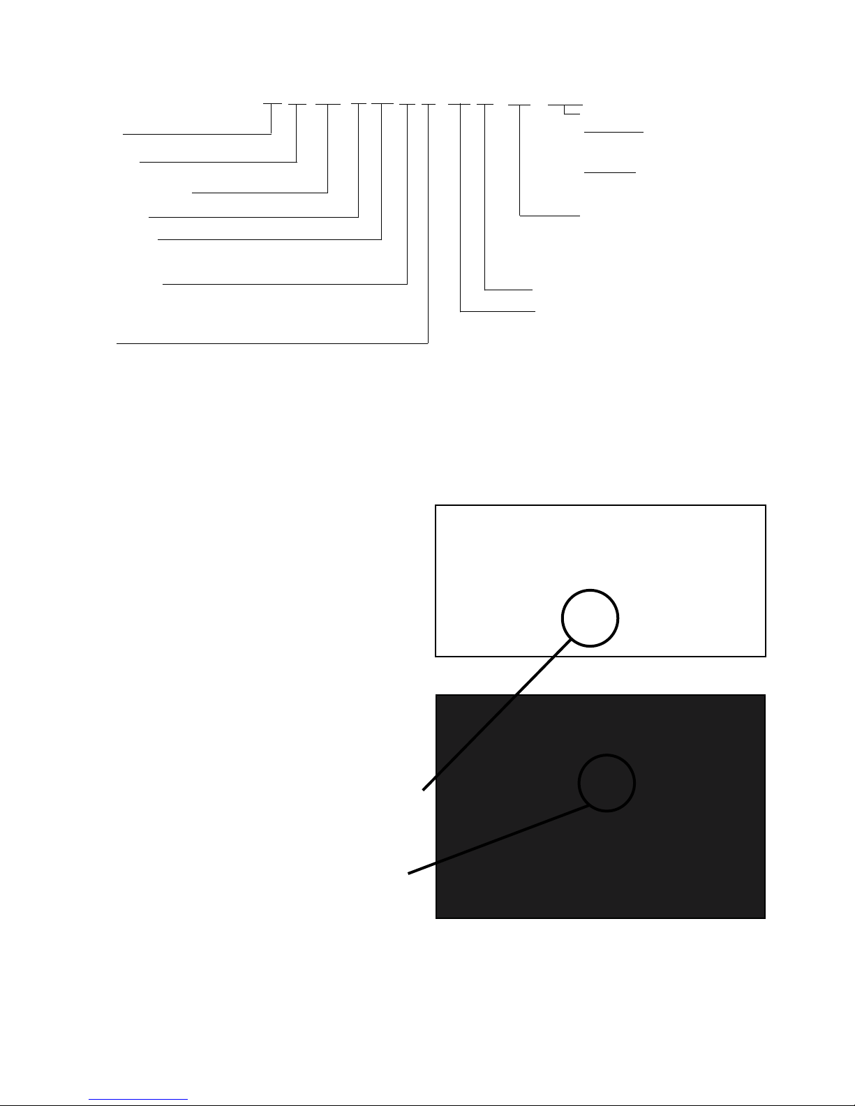
T P LP 3 14 L E S2 B R6 - ESPE
T = Trenton
Pre-Assembled
Low Prole Evaporator
Number of Fans
Nominal Capacity:
x 1000 @ 10°F TD, Btu/H, R404A
Application Range:
M = Medium to High Temp 6 FPI (25°F / -4°C) Evap T emp)
L = Low Temp 6 FPI (-20°F / -29°C) Evap Temp)
V = Low Temp 4 FPI (-20°F / -29°C) Evap T emp)
Defrost*:
A = Air E = Electric
STANDARD FEATURES (ALL MODELS)
Designation:
Mechanical:
if blank = PSC Motor
EC2 = SmartSpeed EC Motor
Electronic:
ESPP = ESP+ w/ PSC Motor
ESPE = ESP+ w/ EC Motor
Refrigerant Designation:
R2 = R407A / R407C / R22 / R448A
R6 = R404A
R8 = R407A / R407C / R22 / R448A, R404A
(R8 applies to ESP+ models only)
Generation: B = 2
Voltage:
S1 = 115/1/60 (air defrost models only)
S2 = 208-230/1/60
S4 = 460/1/60 (2 to 6 fan models only)
T3 = 208-230/3/60
nd
• Compatible with Low GWP Refrigerants
• High eciency and high strength fan guard
• Front access
• Internally enhanced tubing
• Convenient mounting brackets
• Ample electrical and header compartments
• Positive slope, hinged drain pan
• Centrally located, universal drain connection
• Large 3/4” ID (3/4” MPT) drain hole
• Schrader valve on suction header, located
outside of cabinet
Page 3
TPLP 60Hz
29/11/18
T30-TPLP-PDI-14
- 3 -
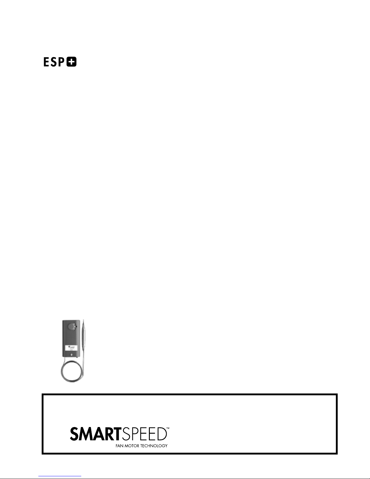
PRE-ASSEMBLED CONFIGURATIONS
(R8) MODELS
Include factory installed:
• ESP+ Adaptive Defrost Control
• ESP+ Remote Display
• EEV Electronic Expansion Valve
• Solenoid Valve
ELECTRO-MECHANICAL
(R2 and R6) MODELS
Include factory installed:
• TX Valve
• Solenoid Valve
• Thermostat
ALL CONFIGURATIONS AVAILABLE WITH:
OR
PSC MOTORS
Page 4
TPLP 60Hz
29/11/18
T30-TPLP-PDI-14
- 4 -
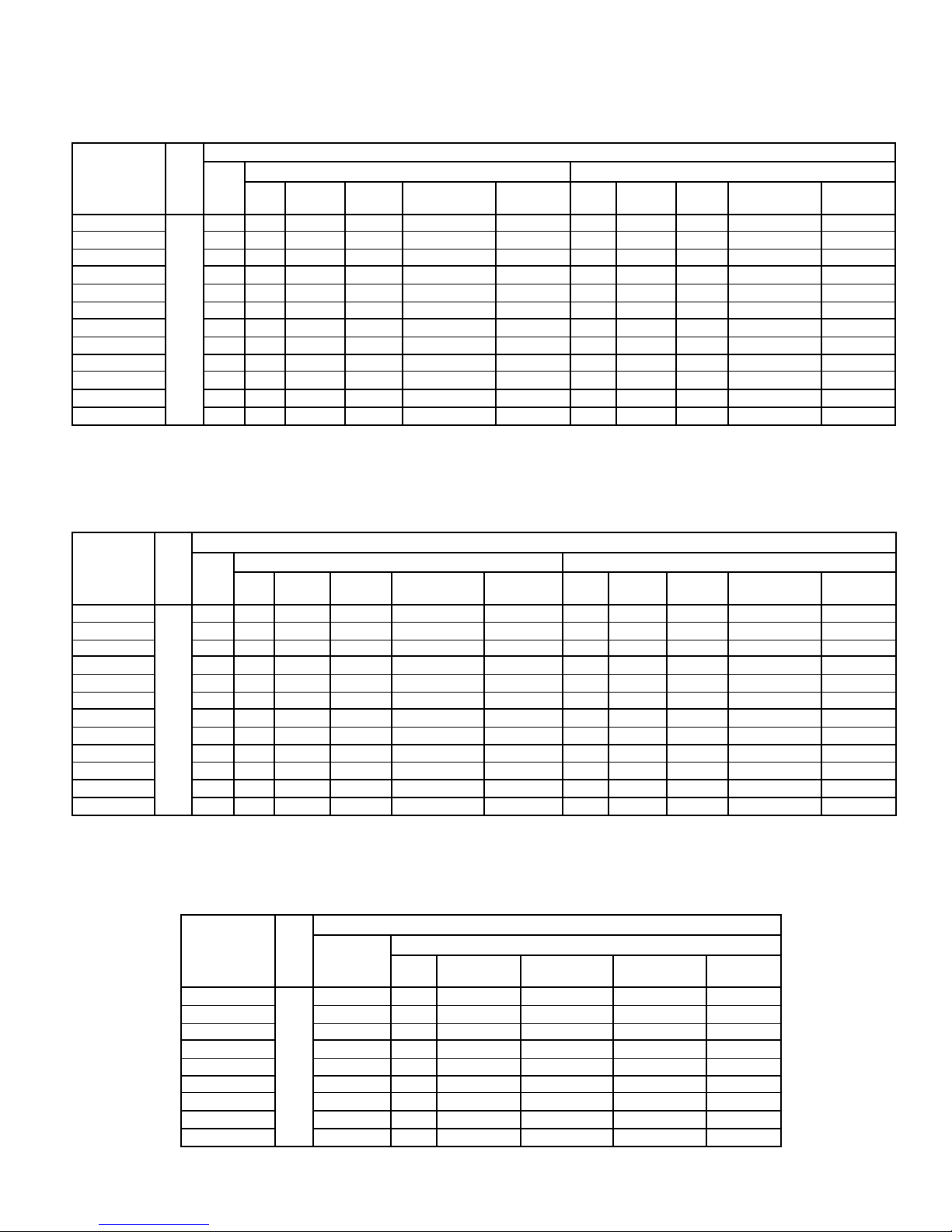
CAPACITY DATA - ALL MODELS
Medium Temperature Models - Capacity @ 6 F.P.I.
Medium Temp. Models TPLP 104M 106M 107M 209M 211M 214M 317M 320M 423M 426M 532M 639M
Number Of Fans 1 1 1 2 2 2 3 3 4 4 5 6
4090 5230 6460 8170 10450 13300 16200 19000 21900 24700 30400 37100
(1197) (1530) (1891) (2394) (3059) (3895) (4731) (5567) (6403) (7230) (8902) (10830)
3870 4950 6120 7740 9900 12600 15400 18100 20800 23500 28900 35200
(1134) (1449) (1791) (2268) (2898) (3690) (4482) (5274) (6066) (6849) (8433) (10260)
4300 5500 6800 8600 11000 14000 17000 20000 23000 26000 32000 39000
(1260) (1610) (1990) (2520) (3220) (4100) (4980) (5860) (6740) (7610) (9370) (11400)
4090 5230 6460 8170 10500 13300 16200 19000 21900 24700 30400 37100
(1197) (1530) (1891) (2394) (3059) (3895) (4731) (5567) (6403) (7230) (8902) (10830)
1010
(477)
0.7
(0.3)
950
(458)
1.1
(0.5)
900
(425)
1.5
(0.7)
2020
(953)
1.3
(0.6)
1910
(901)
1.4
(0.6)
1800
(850)
2.0
(0.9)
2860
(1350)
3.0
(1.4)
2700
(1274)
4.0
(1.8)
3810
(1798)
3.9
(1.8)
3600
(1699)
3.3
(1.5)
4500
(2124)
6.5
(2.9)
5400
(2549)
7.8
(3.5)
Capacity
BTUH
(WATTS)
Air Flow CFM (L/S)
Refrigerant **
Charge
Evap
Temp.
25°F
(-4°C)
R407A
LB. (KG)
R407A
R448A
R407C
R404A
R507
R22
Low Temperature Models - Capacity @ 6 F.P.I.
Low Temp. Models TPLP 104L 105L 106L 207L 209L 211L 314L 317L 419L 422L 527L 631L
Number Of Fans 1 1 1 2 2 2 3 3 4 4 5 6
Capacity
BTUH
(WATTS)
Air Flow CFM (L/S)
Refrigerant **
Charge
Evap
Temp.
-20°F
(-29°C)
R407A
LB. (KG)
R407A
R448A
R404A
R507
3610 4560 5510 7030 8550 10500 13300 16200 18100 20900 25700 29500
(1055) (1340) (1615) (2062) (2508) (3059) (3895) (4731) (5292) (6118) (7515) (8626)
3800 4800 5800 7400 9000 11000 14000 17000 19000 22000 27000 31000
(1110) (1410) (1700) (2170) (2640) (3220) (4100) (4980) (5570) (6440) (7910) (9080)
1010
(477)
0.7
(0.3)
950
(458)
1.1
(0.5)
900
(425)
1.5
(0.7)
2020
(953)
1.3
(0.6)
1910
(901)
1.4
(0.6)
1800
(850)
2.0
(0.9)
2860
(1350)
3.0
(1.4)
2700
(1274)
4.0
(1.8)
3810
(1798)
3.9
(1.8)
3600
(1699)
3.3
(1.5)
4500
(2124)
6.5
(2.9)
5400
(2549)
7.8
(3.5)
Low Temperature Models - Capacity @ 4 F.P.I.
Low Temp. 4 FPI Models TPLP 103V 104V 105V 206V 208V 209V 312V 315V 416V 419V 523V 627V
Number Of Fans 1 1 1 2 2 2 3 3 4 4 5 6
R407A
Capacity
BTUH
(WATTS)
Air Flow CFM (L/S)
Refrigerant **
Charge
Capacities rated using 10°F (5.6°C) TD & 100°F (38°C) liquid temperature.
Capacities at other TD within a range of 8 to 15 °F (4.4 to 8.3°C) are directly proportional to TD, or use formula: Capacity = Rated capacity ÷ 10 x TD.
Capacities for R448A, R407A and R407C are based on mean temperature. Mean temperature is the average temperature between the saturated suction
temperature and the temperature feeding the evaporator. For dew point ratings, consult factory.
For R449A, use R448A data.
** REFRIGERANT CHARGE CONVERSION FACTORS
R448A
0.96 0.99 0.92 0.93 1.02
Evap
Temp.
-20°F
(-29°C)
R407A
LB. (KG)
R407C R404A
R448A
R404A
R507
2850 3900 4750 6080 7410 8840 11400 14300 15200 18100 21900 25700
(836) (1140) (1397) (1786) (2176) (2584) (3344) (4171) (4456) (5292) (6403) (7515)
3000 4100 5000 6400 7800 9300 12000 15000 16000 19000 23000 27000
(880) (1200) (1470) (1880) (2290) (2720) (3520) (4390) (4690) (5570) (6740) (7910)
1010
(477)
0.7
(0.3)
R507
950
(458)
1.1
(0.5)
R22
900
(425)
1.5
(0.7)
2020
(953)
1.3
(0.6)
1910
(901)
1.4
(0.6)
1800
(850)
2.0
(0.9)
2860
(1350)
3.0
(1.4)
2700
(1274)
4.0
(1.8)
3810
(1798)
3.9
(1.8)
3600
(1699)
3.3
(1.5)
4500
(2124)
6.5
(2.9)
5400
(2549)
7.8
(3.5)
Page 5
TPLP 60Hz
29/11/18
T30-TPLP-PDI-14
- 5 -
ELECTRICAL DATA
115/1/60 - AIR DEFROST MODELS
MODEL
TPLP
104MAS1
106MAS1 1 1/15 1.0 100 1.3 15 1/15 1.0 60 1.3 15
107MAS1 1 1/15 1.0 100 1.3 15 1/15 1.0 60 1.3 15
209MAS1 2 1/15 2.0 200 2.3 15 1/15 2.0 120 2.3 15
211MAS1 2 1/15 2.0 200 2.3 15 1/15 2.0 120 2.3 15
214MAS1 2 1/15 2.0 200 2.3 15 1/15 2.0 120 2.3 15
317MAS1 3 1/15 3.0 300 3.3 15 1/15 3.0 180 3.3 15
320MAS1 3 1/15 3.0 300 3.3 15 1/15 3.0 180 3.3 15
423MAS1 4 1/15 4.0 400 4.3 15 1/15 4.0 240 4.3 15
426MAS1 4 1/15 4.0 400 4.3 15 1/15 4.0 240 4.3 15
532MAS1 5 1/15 5.0 500 5.3 15 1/15 5.0 300 5.3 15
639MAS1 6 1/15 6.0 600 6.3 15 1/15 6.0 360 6.3 15
FPI
QTY.
1 1/15 1.0 100 1.3 15 1/15 1.0 60 1.3 15
6
HP
FLA
TOTAL
PSC MOTORS EC MOTORS
WATTS
MIN. CIRC.
AMPACITY (A)
FAN MOTORS
MAX. FUSE
(AMPS)
HP
FLA
TOTAL
WATTS
MIN. CIRC.
AMPACITY (A)
MAX. FUSE
(AMPS)
ELECTRICAL DATA
208-230/1/60 - AIR DEFROST MODELS
MODEL
TPLP
104MAS2
106MAS2 1 1/15 0.5 100 0.6 15 1/15 0.6 60 0.8 15
107MAS2 1 1/15 0.5 100 0.6 15 1/15 0.6 60 0.8 15
209MAS2 2 1/15 1.0 200 1.1 15 1/15 1.2 120 1.4 15
211MAS2 2 1/15 1.0 200 1.1 15 1/15 1.2 120 1.4 15
214MAS2 2 1/15 1.0 200 1.1 15 1/15 1.2 120 1.4 15
317MAS2 3 1/15 1.5 300 1.6 15 1/15 1.8 180 2.0 15
320MAS2 3 1/15 1.5 300 1.6 15 1/15 1.8 180 2.0 15
423MAS2 4 1/15 2.0 400 2.1 15 1/15 2.4 240 2.6 15
426MAS2 4 1/15 2.0 400 2.1 15 1/15 2.4 240 2.6 15
532MAS2 5 1/15 2.5 500 2.6 15 1/15 3.0 300 3.2 15
639MAS2 6 1/15 3.0 600 3.1 15 1/15 3.6 360 3.8 15
FPI
QTY.
1 1/15 0.5 100 0.6 15 1/15 0.6 60 0.8 15
6
HP
FLA
TOTAL
PSC MOTORS EC MOTORS
WATTS
MIN. CIRC.
AMPACITY (A)
FAN MOTORS
MAX. FUSE
(AMPS)
HP
FLA
TOTAL
WATTS
MIN. CIRC.
AMPACITY (A)
MAX. FUSE
(AMPS)
460/1/60 - AIR DEFROST MODELS
MODEL
TPLP
209MAS4
211MAS4 2 1/15 0.8 200 0.9 15
214MAS4 2 1/15 0.8 200 0.9 15
317MAS4 3 1/15 1.2 300 1.3 15
320MAS4 3 1/15 1.2 300 1.3 15
423MAS4 4 1/15 1.6 400 1.7 15
426MAS4 4 1/15 1.6 400 1.7 15
532MAS4 5 1/15 2.0 500 2.1 15
639MAS4 6 1/15 2.4 600 2.5 15
FPI
6
ELECTRICAL DATA
FAN MOTORS
PSC MOTORS
QUANTITY
2 1/15 0.8 200 0.9 15
HP
FLA
TOTAL
WATTS
MIN. CIRC.
AMPACITY (A)
MAX. FUSE
(AMPS)
Page 6
TPLP 60Hz
29/11/18
T30-TPLP-PDI-14
- 6 -
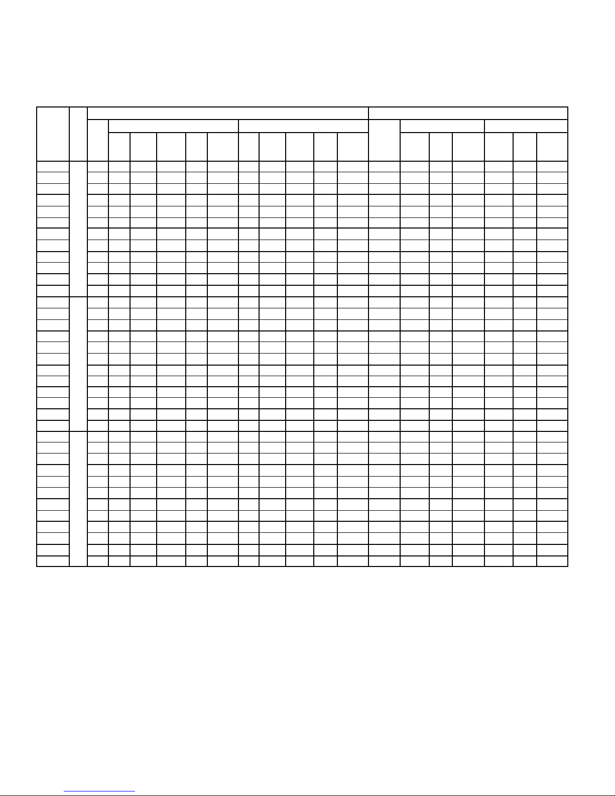
ELECTRICAL DATA -
208-230/1/60 & 208-230/3/60
ELECTRIC DEFROST MODELS
FAN MOTORS DEFROST HEATERS
MODEL
TPLP
104ME*
106ME* 1 1/15 0.5 100 0.6 15 1/15 0.6 60 0.8 15 1060 4.6 5.8 15 3.0 3.8 15
107ME* 1 1/15 0.5 100 0.6 15 1/15 0.6 60 0.8 15 1060 4.6 5.8 15 3.0 3.8 15
209ME* 2 1/15 1.0 200 1.1 15 1/15 1.2 120 1.4 15 1890 8.2 10.3 15 5.3 6.7 15
211ME* 2 1/15 1.0 200 1.1 15 1/15 1.2 120 1.4 15 1890 8.2 10.3 15 5.3 6.7 15
214ME* 2 1/15 1.0 200 1.1 15 1/15 1.2 120 1.4 15 1890 8.2 10.3 15 5.3 6.7 15
317ME* 3 1/15 1.5 300 1.6 15 1/15 1.8 180 2.0 15 2730 11.9 14.8 15 7.7 10 15
320ME* 3 1/15 1.5 300 1.6 15 1/15 1.8 180 2.0 15 2730 11.9 14.8 15 7.7 10 15
423ME* 4 1/15 2.0 400 2.1 15 1/15 2.4 240 2.6 15 3560 15.5 19.3 20 10 12 15
426ME* 4 1/15 2.0 400 2.1 15 1/15 2.4 240 2.6 15 3560 15.5 19.3 20 10 12 15
532ME* 5 1/15 2.5 500 2.6 15 1/15 3.0 300 3.2 15 4400 19.1 23.9 25 12 15.1 20
639ME* 6 1/15 3.0 600 3.1 15 1/15 3.6 360 3.8 15 5230 22.7 28.4 30 15 18 20
104LE*
105LE* 1 1/15 0.5 100 0.6 15 1/15 0.6 60 0.75 15 1060 4.6 5.8 15 3.0 3.8 15
106LE* 1 1/15 0.5 100 0.6 15 1/15 0.6 60 0.75 15 1060 4.6 5.8 15 3.0 3.8 15
207LE* 2 1/15 1.0 200 1.1 15 1/15 1.2 120 1.4 15 1890 8.2 10.3 15 5.3 6.7 15
209LE* 2 1/15 1.0 200 1.1 15 1/15 1.2 120 1.4 15 1890 8.2 10.3 15 5.3 6.7 15
211LE* 2 1/15 1.0 200 1.1 15 1/15 1.2 120 1.4 15 1890 8.2 10.3 15 5.3 6.7 15
314LE* 3 1/15 1.5 300 1.6 15 1/15 1.8 180 2.0 15
317LE* 3 1/15 1.5 300 1.6
419LE* 4 1/15 2.0 400 2.1 15 1/15 2.4 240 2.6 15 3560 15.5 19.3 20 10 12 15
422LE* 4 1/15 2.0 400 2.1 15 1/15 2.4 240 2.6 15 3560 15.5 19.3 20 10 12 15
527LE* 5 1/15 2.5 500 2.6 15 1/15 3.0 300 3.2 15 4400 19.1 23.9 25 12 15.1 20
631LE* 6 1/15 3.0 600 3.1 15 1/15 3.6 360 3.8 15 5230 22.7 28.4 30 15 18 20
103VE*
104VE* 1 1/15 0.5 100 0.6 15 1/15 0.6 60 0.75 15 1060 4.6 5.8 15 3.0 3.8 15
105VE* 1 1/15 0.5 100 0.6 15 1/15 0.6 60 0.75 15 1060 4.6 5.8 15 3.0 3.8 15
206VE* 2 1/15 1.0 200 1.1 15 1/15 1.2 120 1.4 15 1890 8.2 10.3 15 5.3 6.7 15
208VE* 2 1/15 1.0 200 1.1 15 1/15 1.2 120 1.4 15 1890 8.2 10.3 15 5.3 6.7 15
209VE* 2 1/15 1.0 200 1.1 15 1/15 1.2 120 1.4 15 1890 8.2 10.3 15 5.3 6.7 15
312VE* 3 1/15 1.5 300 1.6 15 1/15 1.8 180 2.0 15 2730 11.9 14.8 15 7.7 10 15
315VE* 3 1/15 1.5 300 1.6 15 1/15 1.8 180 2.0 15 2730 11.9 14.8 15 7.7 10 15
416VE* 4 1/15 2.0 400 2.1 15 1/15 2.4 240 2.6 15 3560 15.5 19.3 20 10 12 15
419VE* 4 1/15 2.0 400 2.1 15 1/15 2.4 240 2.6 15 3560 15.5 19.3 20 10 12 15
523VE* 5 1/15 2.5 500 2.6 15 1/15 3.0 300 3.2 15 4400 19.1 23.9 25 12 15.1 20
627VE* 6 1/15 3.0 600 3.1 15 1/15 3.6 360 3.8 15 5230 22.7 28.4 30 15 18 20
* = S2 or T3. Refer to Nomenclature for details
FPI
QTY.
HP
1 1/15 0.5 100 0.6 15 1/15 0.6 60 0.8 15 1060 4.6 5.8 15 3.0 3.8 15
6
1 1/15 0.5 100 0.6 15 1/15 0.6 60 0.75 15 1060 4.6 5.8 15 3.0 3.8 15
6
1 1/15 0.5 100 0.6 15 1/15 0.6 60 0.75 15 1060 4.6 5.8 15 3.0 3.8 15
4
PSC MOTORS EC MOTORS
FLA
TOTAL
WATTS
MCA
(A)
MAX.
FUSE
(AMPS)
15 1/15 1.8 180 2.0 15 2730 11.9 14.8 15 7.7 10 15
HP
FLA
TOTAL
WATTS
MCA
(A)
MAX.
FUSE
(AMPS)
TOTAL
WATTS
2730 11.9 14.8 15 7.7 10 15
208-230/1/60 208-230/3/60
MCA
(A)
MAX.
FUSE
(AMPS)
TOTAL
AMPS
TOTAL
AMPS
MCA
(A)
(AMPS)
MAX.
FUSE
Page 7
TPLP 60Hz
29/11/18
T30-TPLP-PDI-14
- 7 -
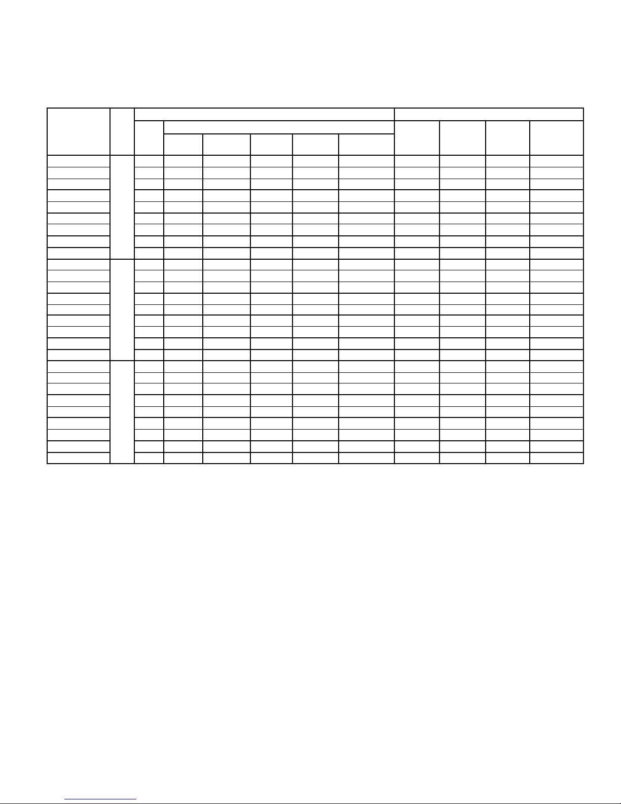
ELECTRICAL DATA - 460/1/60
ELECTRIC DEFROST MODELS
MODEL
TPLP
209MES4
211MES4 2 1/15 0.8 200 0.9 15 1890 4.1 5.1 15
214MES4 2 1/15 0.8 200 0.9 15
317MES4 3 1/15 1.2 300 1.3 15
320MES4 3 1/15 1.2 300 1.3 15
423MES4 4 1/15 1.6 400 1.7 15
426MES4 4 1/15 1.6 400 1.7 15
532MES4 5 1/15 2.0 500 2.1 15 4400 9.6 12.0 15
639MES4 6 1/15 2.4 600 2.5 15 5230 11.4 14.2 15
207LES4
209LES4 2 1/15 0.8 200 0.9 15 1890 4.1 5.1 15
211LES4 2 1/15 0.8 200 0.9 15
314LES4 3 1/15 1.2 300 1.3 15
317LES4 3 1/15 1.2 300 1.3 15
419LES4 4 1/15 1.6 400 1.7 15
422LES4 4 1/15 1.6 400 1.7 15
527LES4 5 1/15 2.0 500 2.1 15 4400 9.6 12.0 15
631LES4 6 1/15 2.4 600 2.5 15 5230 11.4 14.2 15
206VES4
208VES4 2 1/15 0.8 200 0.9 15 1890 4.1 5.1 15
209VES4 2 1/15 0.8 200 0.9 15
312VES4 3 1/15 1.2 300 1.3 15
315VES4 3 1/15 1.2 300 1.3 15
416VES4 4 1/15 1.6 400 1.7 15
419VES4 4 1/15 1.6 400 1.7 15
523VES4 5 1/15 2.0 500 2.1 15 4400 9.6 12.0 15
627VES4 6 1/15 2.4 600 2.5 15 5230 11.4 14.2 15
FPI
6
6
4
QTY.
HP
2 1/15 0.8 200 0.9 15
2 1/15 0.8 200 0.9 15
2 1/15 0.8 200 0.9 15
FAN MOTORS DEFROST HEATERS
FLA
TOTAL
PSC MOTORS
WATTS
MCA
(A)
MAX. FUSE
(AMPS)
TOTAL
WATTS
1890 4.1 5.1 15
1890 4.1 5.1 15
2730 5.9 7.4 15
2730 5.9 7.4 15
3560 7.7 9.7 15
3560 7.7 9.7 15
1890 4.1 5.1 15
1890 4.1 5.1 15
2730 5.9 7.4 15
2730 5.9 7.4 15
3560 7.7 9.7 15
3560 7.7 9.7 15
1890 4.1 5.1 15
1890 4.1 5.1 15
2730 5.9 7.4 15
2730 5.9 7.4 15
3560 7.7 9.7 15
3560 7.7 9.7 15
TOTAL
AMPS
MCA
(A)
MAX. FUSE
(AMPS)
Page 8
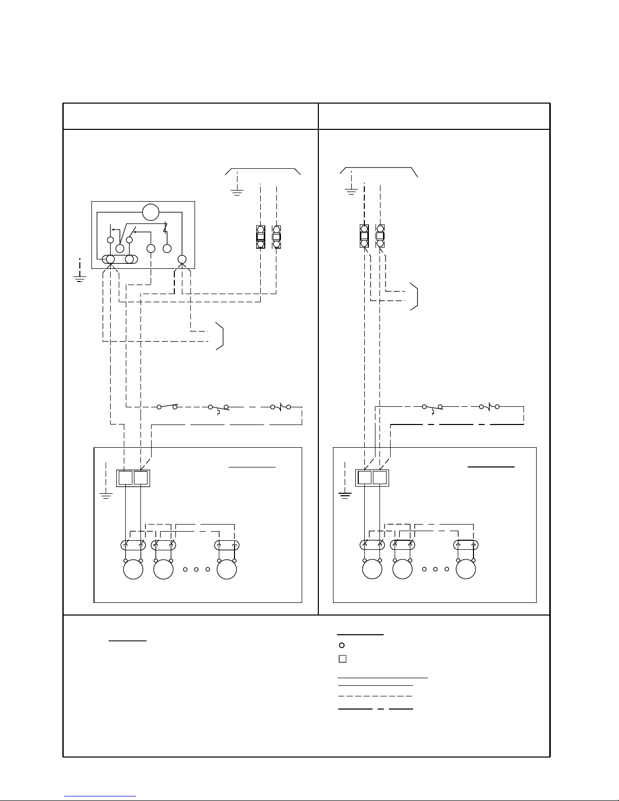
CONDUCTORS/WIRING
AND NATIONAL CODES.
-TERMINAL BLOCK TERMINAL
ALL FIELD WIRING MUST BE DONE IN
COMPLIANCE WITH ALL APPLICABLE LOCAL
-COMPONENT TERMINAL
4). MAY BE FACTORY INSTALLED-MOUNTED AND
3). OVERCURRENT PROTECTION FOR
1). USE COPPER CONDUCTORS ONLY
VALUE SHOWN ON EVAPORATOR NAMEPLATE.
HEATERS MUST NOT EXCEED MAXIMUM
EVAPORATOR FAN MOTORS AND DEFROST
2). USE 75°C WIRE (OR HIGHER)
WIRED ON EVAPORATOR .
NOTES
TERMINALS
OPTIONAL FACTORY OR
1-LP AIR 09/06
BY OTHERS
WIRING BY OTHERS
FACTORY WIRING
WITHOUT DEFROST TIME CLOCK
REQUIREMENTS
REFER TO EVAPORATOR
NAMEPLATE FOR ELECTRICAL
L1
PARAGON # 8145
DEFROST CLOCK
OR EQUIVALENT
THERMOSTAT
CIRCUIT
FUSE OR
NOTE #3
BREAKER
SWITCH
PUMP DOWN
(IF USED)
NOTE #4
SPACE
LIQUID LINE
SOLENOID VALVE
NOTE #4
N.C.
WITH DEFROST TIME CLOCK
GND
L1
GND
SOLENOID VALVE
THERMOSTAT
BREAKER
NOTE #3
FUSE OR
CIRCUIT
SPACE
NOTE #4
IF(N)
2ND FUSE
OMIT
LIQUID LINE
NOTE #4
N.C.
L2(N)
1
TM
3
2
4X
N
REFER TO
EVAPORATOR
DATA PLATE
FOR MOTOR
QUANTITY
GND.
FAN
MTR
FAN
MTR
FAN
MTR
EVAPORATOR
TERMINAL BOARD
F
4
FAN MOTOR
POWER
PLUGS
FAN
MTR
FAN
MTR
FAN
MTR
F
GND.
4
TERMINAL BOARD
REFER TO
EVAPORATOR
DATA PLATE
FOR MOTOR
QUANTITY
FAN MOTOR
POWER
PLUGS
EVAPORATOR
IF(N)
OMIT 2ND
L2(N)
4
F
TO MULTIPLE EVAPS
(IF APPLIC)
4
F
EVAPORATORS (IF APPLIC)
TO MULTIPLE
FUSE
GND
REQUIREMENTS
REFER TO EVAPORATOR
NAMEPLATE FOR ELECTRICAL
TPLP
29/11/18
T30-TPLP-PDI-14
- 8 -
WIRING DIAGRAM - 115/1/60, 208-230/1/60
STANDARD PSC MOTORS
AIR DEFROST MODELS
PSC
60Hz
Page 9
CONDUCTORS/WIRING
AND NATIONAL CODES.
-TERMINAL BLOCK TERMINAL
ALL FIELD WIRING MUST BE DONE IN
COMPLIANCE WITH ALL APPLICABLE LOCAL
-COMPONENT TERMINAL
4). MAY BE FACTORY INSTALLED-MOUNTED AND
3). OVERCURRENT PROTECTION FOR
1). USE COPPER CONDUCTORS ONLY
VALUE SHOWN ON EVAPORATOR NAMEPLATE.
HEATERS MUST NOT EXCEED MAXIMUM
EVAPORATOR FAN MOTORS AND DEFROST
2). USE 75°C WIRE (OR HIGHER)
WIRED ON EVAPORATOR .
NOTES
TERMINALS
OPTIONAL FACTORY OR
6-LP 460 AIR 09/06
BY OTHERS
WIRING BY OTHERS
FACTORY WIRING
WITHOUT DEFROST TIME CLOCK
L1
PARAGON # 8145
DEFROST CLOCK
OR EQUIVALENT
THERMOSTAT
CIRCUIT
FUSE OR
NOTE #3
BREAKER
SWITCH
PUMP DOWN
(IF USED)
NOTE #4
SPACE
LIQUID LINE
SOLENOID VALVE
NOTE #4
N.C.
WITH DEFROST TIME CLOCK
380/400-1-50Hz
CONTROL VOLTAGE
GND
L1
GND
IF(N)
2ND FUSE
OMIT
L2
1
TM
3
2
4X
N
REFER TO
EVAPORATOR
DATA PLATE
FOR MOTOR
QUANTITY
GND.
FAN
MTR
FAN
MTR
FAN
MTR
EVAPORATOR
FAN MOTOR
POWER
PLUGS
FAN
MTR
FAN
MTR
FAN
MTR
M2
GND.
M1
TERMINAL BOARD
REFER TO
EVAPORATOR
DATA PLATE
FOR MOTOR
QUANTITY
FAN MOTOR
POWER
PLUGS
EVAPORATOR
IF(N)
OMIT 2ND
L2
TO MULTIPLE
EVAPORATORS (IF APPLIC)
M1
M2
EVAPORATORS (IF APPLIC)
TO MULTIPLE
FUSE
GND
4
N
GND
L2(N)
L1
460-1-60 Hz
M2
M1
TERMINAL BOARD
N
4
THERMOSTAT
NOTE #4
N.C.
SOLENOID VALVE
SPACE
LIQUID LINE
NOTE #4
GND
L1
L2(N)
460-1-60 Hz
380/400-1-50Hz
CONTROL VOLTAGE
M1
M2
NOTE #3
CIRCUIT
BREAKER
FUSE OR
TPLP
29/11/18
T30-TPLP-PDI-14
- 9 -
WIRING DIAGRAM - 460/1/60
STANDARD PSC MOTORS
AIR DEFROST MODELS
PSC
60Hz
Page 10
WARNING
EVAP FIELD MODIFICATION
MUST BE MADE
REFER TO EVAPORATOR
COMPR INTERLOCK
FOR ALL MODELS WITHOUT DEFROST HEATER CONTACTOR
THERMOSTAT
NOTE #4
EVAPORATOR FAN MOTORS AND
DEFROST HEATERS MUST NOT EXCEED
1). USE COPPER CONDUCTORS ONLY
3). OVERCURRENT PROTECTION FOR
MAXIMUM VALUE SHOWN ON
EVAPORATOR NAMEPLATE.
NOTES
2). USE 75°C WIRE (OR HIGHER)
FAN
MTR
DEFROST TERMINATION
CONTROL
(10.0A MAX.)
& FAN DELAY
FD-FAN DELAY
DT-DEFROST TERM
X
F
4
BK
GND.
C
FD
DT
BN
RD
(IF USED)
SWITCH
OR EQUIVALENT
PUMP DOWN
SPACE
(IF USED)
21
N
TM
4X
3
DEFROST CLOCK
PARAGON # 8145
EVAPORATOR
OPTIONAL FACTORY
FACTORY WIRING
WIRING BY OTHERS
ALL FIELD WIRING MUST BE DONE IN
COMPLIANCE WITH ALL APPLICABLE LOCAL
AND NATIONAL CODES.
2-LP ED 12/07
-TERMINAL BLOCK TERMINAL
-COMPONENT TERMINAL
CONDUCTORS/WIRING
TERMINALS
DATA PLATE FOR
MOTOR QUANTITY
EVAPORATOR
REFER TO
POWER PLUGS
FAN MOTOR
H2
H1
NOTE #4
SOL VALVE
L2L1
N.C.
LIQUID LINE
GND
NAMEPLATE FOR ELECTRICAL
REQUIREMENTS
OR BY OTHERS
AND WIRED ON EVAPORATOR
4.) MAY BE FACTORY INSTALLED-MOUNTED
DEFROST HEATERS
CIRCUIT
BREAKER
FUSE OR
USING MAXIMUM 15A HEATER OVERCURRENT PROTECTION
15A
N
1
FAN
MTR
2
FAN
MTR
6
H3
3
WH
YL
ORANGE JUMPER
SWITCH
LIMIT
HEATER
(10.0A MAX.)
1
2
FROM H2 TO N
INSTALL ORANGE JUMPER
(SUPPLIED LOOSE)
N TO H1 AS SHOWN
RELOCATE WHITE WIRE FROM
2
1
SEE NOTE:
TPLP
29/11/18
T30-TPLP-PDI-14
- 10 -
WIRING DIAGRAM - 208-230/1/60
PSC
60Hz
STANDARD PSC MOTORS
ELECTRIC DEFROST MODELS - SINGLE EVAPORATOR 10A MAX.
Page 11
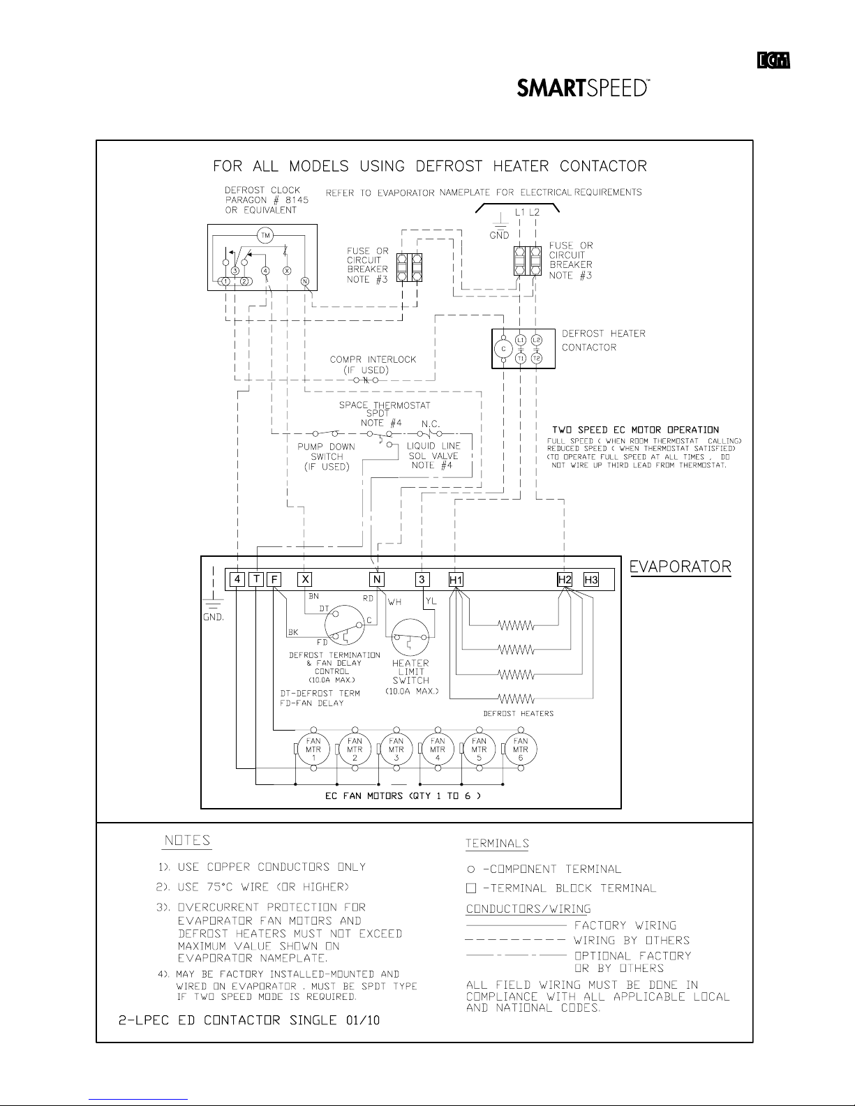
COMPR INTERLOCK
FOR ALL MODELS USING DEFROST HEATER CONTACTOR
THERMOSTAT
NOTE #4
EVAPORATOR FAN MOTORS AND
DEFROST HEATERS MUST NOT EXCEED
1). USE COPPER CONDUCTORS ONLY
3). OVERCURRENT PROTECTION FOR
MAXIMUM VALUE SHOWN ON
EVAPORATOR NAMEPLATE.
NOTES
2). USE 75°C WIRE (OR HIGHER)
(IF USED)
SWITCH
OR EQUIVALENT
PUMP DOWN
SPACE
(IF USED)
21
N
TM
4X
3
DEFROST CLOCK
PARAGON # 8145
OPTIONAL FACTORY
FACTORY WIRING
WIRING BY OTHERS
ALL FIELD WIRING MUST BE DONE IN
COMPLIANCE WITH ALL APPLICABLE LOCAL
AND NATIONAL CODES.
3-LP ED CONTACTOR SINGLE 12/07
-TERMINAL BLOCK TERMINAL
-COMPONENT TERMINAL
CONDUCTORS/WIRING
TERMINALS
NOTE #4
SOL VALVE
N.C.
LIQUID LINE
OR BY OTHERS
AND WIRED ON EVAPORATOR
4.) MAY BE FACTORY INSTALLED-MOUNTED
CIRCUIT
BREAKER
NOTE #3
FUSE OR
CONTACTOR
DEFROST HEATER
T2
T1
C
L2
L1
NOTE #3
BREAKER
FUSE OR
CIRCUIT
GND
L2L1
YL
(10.0A MAX.)
REFER TO
POWER PLUGS
MOTOR QUANTITY
DATA PLATE FOR
EVAPORATOR
FAN MOTOR
N
3
X
F
4
621
DEFROST TERMINATION
FD-FAN DELAY
DT-DEFROST TERM
FAN
MTR
GND.
BK
FAN
MTRMTR
FAN
RD
C
(10.0A MAX.)
CONTROL
& FAN DELAY
FD
DT
BN
LIMIT
SWITCH
HEATER
WH
H3
H2
H1
EVAPORATOR
DEFROST HEATERS
REFER TO EVAPORATOR NAMEPLATE
FOR ELECTRICAL REQUIREMENTS
TPLP
29/11/18
T30-TPLP-PDI-14
- 11 -
WIRING DIAGRAM - 208-230/1/60
STANDARD PSC MOTORS
ELECTRIC DEFROST MODELS - SINGLE EVAPORATOR
PSC
60Hz
Page 12

COMPR INTERLOCK
FOR ALL MODELS USING 3 PHASE DEFROST HEATER CONTACTOR
THERMOSTAT
NOTE #4
EVAPORATOR FAN MOTORS AND
DEFROST HEATERS MUST NOT EXCEED
1). USE COPPER CONDUCTORS ONLY
3). OVERCURRENT PROTECTION FOR
MAXIMUM VALUE SHOWN ON
EVAPORATOR NAMEPLATE.
NOTES
2). USE 75°C WIRE (OR HIGHER)
(IF USED)
SWITCH
OR EQUIVALENT
PUMP DOWN
SPACE
(IF USED)
21
N
TM
4X
3
DEFROST CLOCK
PARAGON # 8145
OPTIONAL FACTORY
FACTORY WIRING
WIRING BY OTHERS
ALL FIELD WIRING MUST BE DONE IN
COMPLIANCE WITH ALL APPLICABLE LOCAL
AND NATIONAL CODES.
3A-LP ED 3ph.CONTACTOR SINGLE 12/07
-TERMINAL BLOCK TERMINAL
-COMPONENT TERMINAL
CONDUCTORS/WIRING
TERMINALS
NOTE #4
SOL VALVE
N.C.
LIQUID LINE
OR BY OTHERS
AND WIRED ON EVAPORATOR
4.) MAY BE FACTORY INSTALLED-MOUNTED
CIRCUIT
BREAKER
NOTE #3
FUSE OR
CONTACTOR
DEFROST HEATER
T2
T1
C
L2
L1
NOTE #3
BREAKER
FUSE OR
CIRCUIT
GND
L2L1
L3
T3
L3
DEFROST HEATERS
H1
H2 H3
DATA PLATE FOR
MOTOR QUANTITY
12 6
3
N
F
4
X
DT
CONTROL
(10.0A MAX.)
FD
& FAN DELAY
DT-DEFROST TERM
DEFROST TERMINATION
FD-FAN DELAY
MTR
FAN
MTR
FAN
GND.
BK
BN
SWITCH
(10.0A MAX.)
MTR
FAN
FAN MOTOR
REFER TO
EVAPORATOR
POWER PLUGS
HEATER
LIMIT
RD
WH
C
YL
EVAPORATOR
REFER TO EVAPORATOR NAMEPLATE
FOR ELECTRICAL REQUIREMENTS
TPLP
29/11/18
T30-TPLP-PDI-14
- 12 -
WIRING DIAGRAM - 208-230/3/60
STANDARD PSC MOTORS
ELECTRIC DEFROST MODELS - SINGLE EVAPORATOR
PSC
60Hz
Page 13

REFER TO EVAPORATOR NAMEPLATE
FOR ELECTRICAL REQUIREMENTS
COMPR INTERLOCK
FOR ALL 460V MODELS USING DEFROST HEATER AND FAN CONTACTORS
THERMOSTAT
NOTE #4
EVAPORATOR FAN MOTORS AND
DEFROST HEATERS MUST NOT EXCEED
1). USE COPPER CONDUCTORS ONLY
3). OVERCURRENT PROTECTION FOR
MAXIMUM VALUE SHOWN ON
EVAPORATOR NAMEPLATE.
NOTES
2). USE 75°C WIRE (OR HIGHER)
MTR
FANFAN
MTR
FAN
MTR
M2
M1
GND.
(IF USED)
SWITCH
OR EQUIVALENT
PUMP DOWN
SPACE
(IF USED)
BREAKER
21
N
NOTE #3
TM
4X
3
CIRCUIT
FUSE OR
DEFROST CLOCK
PARAGON # 8145
EVAPORATOR
OPTIONAL FACTORY
FACTORY WIRING
WIRING BY OTHERS
ALL FIELD WIRING MUST BE DONE IN
COMPLIANCE WITH ALL APPLICABLE LOCAL
AND NATIONAL CODES.
7-LP ED CONTACTOR SINGLE 12/07
-TERMINAL BLOCK TERMINAL
-COMPONENT TERMINAL
CONDUCTORS/WIRING
TERMINALS
DATA PLATE FOR
MOTOR QUANTITY
EVAPORTOR
REFER TO
POWER PLUGS
FAN MOTOR
NOTE #4
SOL VALVE
L2L1
N.C.
LIQUID LINE
L2
T2
L1
C
T1
GND
OR BY OTHERS
AND WIRED ON EVAPORATOR
4.) MAY BE FACTORY INSTALLED-MOUNTED
CIRCUIT
BREAKER
NOTE #3
FUSE OR
GND
L2(N)
L1
CONTACTOR
DEFROST HEATER
EVAP FAN
C
CONTACTOR
T2
T1
L2
L1
COIL DEFROST HEATERS
H1 H2
DEFROST TERMINATION
CONTROL
& FAN DELAY
(10.0A MAX.)
FD-FAN DELAY
DT-DEFROST TERM
BK
FD
BN
DT
C
RD
3
X
N
4
F
YL
(10.0A MAX.)
LIMIT
SWITCH
HEATER
WH
TPLP
29/11/18
T30-TPLP-PDI-14
- 13 -
WIRING DIAGRAM - 460/1/60
STANDARD PSC MOTORS
ELECTRIC DEFROST MODELS - SINGLE EVAPORATOR
PSC
60Hz
Page 14

MUST BE MADE
EVAP#2 FIELD MODIFICATION
WARNING
COMPR INTERLOCK
FOR ALL MODELS USING DEFROST HEATER CONTACTOR
THERMOSTAT
NOTE #4
EVAPORATOR FAN MOTORS AND
DEFROST HEATERS MUST NOT EXCEED
1). USE COPPER CONDUCTORS ONLY
3). OVERCURRENT PROTECTION FOR
MAXIMUM VALUE SHOWN ON
EVAPORATOR NAMEPLATE.
NOTES
2). USE 75°C WIRE (OR HIGHER)
MTR
FANFAN
MTR
FAN
MTR
DEFROST TERMINATION
CONTROL
(10.0A MAX.)
& FAN DELAY
FD-FAN DELAY
DT-DEFROST TERM
X
F
4
BK
GND.
C
FD
DT
BN
RD
(IF USED)
SWITCH
OR EQUIVALENT
PUMP DOWN
SPACE
(IF USED)
BREAKER
21
N
NOTE #3
TM
4X
3
CIRCUIT
FUSE OR
DEFROST CLOCK
PARAGON # 8145
EVAPORATOR
OPTIONAL FACTORY
FACTORY WIRING
WIRING BY OTHERS
ALL FIELD WIRING MUST BE DONE IN
COMPLIANCE WITH ALL APPLICABLE LOCAL
AND NATIONAL CODES.
4-LP ED CONTACTOR MULTI 12/07
-TERMINAL BLOCK TERMINAL
-COMPONENT TERMINAL
CONDUCTORS/WIRING
TERMINALS
DATA PLATE FOR
MOTOR QUANTITY
EVAPORATOR
REFER TO
POWER PLUGS
FAN MOTOR
H2
NOTE #4
SOL VALVE
L2
L1
N.C.
LIQUID LINE
L2
T2
L1
C
T1
GND
OR BY OTHERS
AND WIRED ON EVAPORATOR
4.) MAY BE FACTORY INSTALLED-MOUNTED
DEFROST HEATERS
CIRCUIT
BREAKER
NOTE #3
FUSE OR
DEFROST HEATER
CONTACTOR
EVAPORATOR
MTR
FAN
MTR
FANFAN
MTR
FAN MOTOR
POWER PLUGS
EVAPORATOR
MOTOR QUANTITY
DATA PLATE FOR
REFER TO
GND.
4
DT
RD
DEFROST TERMINATION
DT-DEFROST TERM
FD-FAN DELAY
(10.0A MAX.)
CONTROL
& FAN DELAY
BK
FD
C
DEFROST HEATERS
F
X
BN
* Remove & Insulate
* Fan delay not used on second evap / use fan contactor if total fan amps exceeds 10A
PRIMARY
SECONDARY
FUSE OR
BREAKER
NOTE #3
CIRCUIT
H1NH2
H1N
LIMIT
YL
3
(10.0A MAX.)
SWITCH
HEATER
WH
LIMIT
YL
3
(10.0A MAX.)
SWITCH
HEATER
WH
REFER TO EVAPORATOR NAMEPLATE
FOR ELECTRICAL REQUIREMENTS
RELOCATE WHITE WIRE FROM
N AS SHOWN
SEE NOTE:
1
1
REMOVE AND INSULATE
2
AS SHOWN
2
TPLP
29/11/18
T30-TPLP-PDI-14
- 14 -
WIRING DIAGRAM - 208-230/1/60
STANDARD PSC MOTORS
ELECTRIC DEFROST MODELS - MULTIPLE EVAPORATORS
PSC
60Hz
Page 15

WARNING
EVAP#2 FIELD MODIFI-
CATION MUST BE MADE
COMPR INTERLOCK
FOR ALL 460V MODELS USING DEFROST HEATER AND FAN CONTACTORS
THERMOSTAT
NOTE #4
EVAPORATOR FAN MOTORS AND
DEFROST HEATERS MUST NOT EXCEED
1). USE COPPER CONDUCTORS ONLY
3). OVERCURRENT PROTECTION FOR
MAXIMUM VALUE SHOWN ON
EVAPORATOR NAMEPLATE.
NOTES
2). USE 75°C WIRE (OR HIGHER)
MTR
FANFAN
MTR
FAN
MTR
M2
M1
GND.
(IF USED)
SWITCH
OR EQUIVALENT
PUMP DOWN
SPACE
(IF USED)
BREAKER
21
N
NOTE #3
TM
4X
3
CIRCUIT
FUSE OR
DEFROST CLOCK
PARAGON # 8145
EVAPORATOR
OPTIONAL FACTORY
FACTORY WIRING
WIRING BY OTHERS
ALL FIELD WIRING MUST BE DONE IN
COMPLIANCE WITH ALL APPLICABLE LOCAL
AND NATIONAL CODES.
8-LP 460v ED CONTACTOR MULTI 09/06
-TERMINAL BLOCK TERMINAL
-COMPONENT TERMINAL
CONDUCTORS/WIRING
TERMINALS
DATA PLATE FOR
MOTOR QUANTITY
EVAPORATOR
REFER TO
POWER PLUGS
FAN MOTOR
NOTE #4
SOL VALVE
L2
L1
N.C.
LIQUID LINE
L2
T2
L1
C
T1
GND
OR BY OTHERS
AND WIRED ON EVAPORATOR
4.) MAY BE FACTORY INSTALLED-MOUNTED
CIRCUIT
BREAKER
NOTE #3
FUSE OR
GND
L2(N)
L1
CONTACTOR
DEFROST HEATER
EVAP FAN
C
CONTACTOR
T2
T1
L2
L1
MTR
FAN
MTR
FAN
GND.
M1
M2
EVAPORATOR
REFER TO
EVAPORATOR
MOTOR QUANTITY
DATA PLATE FOR
MTR
FAN
POWER PLUGS
FAN MOTOR
NOTE #3
FUSE OR
CIRCUIT
BREAKER
PRIMARY
SECONDARY
* Note: Fan Delay not used on second evap
DEFROST HEATERS
H1 H2
DEFROST TERMINATION
DT-DEFROST TERM
FD-FAN DELAY
CONTROL
(10.0A MAX.)
BK
FD
& FAN DELAY
C
RD
X
4
BN
DT
N
DEFROST TERMINATION
DT-DEFROST TERM
FD-FAN DELAY
CONTROL
(10.0A MAX.)
BK
FD
& FAN DELAY
C
RD
X
4
BN
DT
N
DEFROST HEATERS
H1 H2
*
HEATER
SWITCH
LIMIT
(10.0A MAX.)
YL
WH
3
3
F
F
(10.0A MAX.)
LIMIT
SWITCH
HEATER
YL
WH
N AS SHOWN
RELOCATE WHITE WIRE FROM
1
1
REFER TO EVAPORATOR NAMEPLATE
FOR ELECTRICAL REQUIREMENTS
TPLP
29/11/18
T30-TPLP-PDI-14
- 15 -
WIRING DIAGRAM - 460/1/60
STANDARD PSC MOTORS
ELECTRIC DEFROST MODELS - MULTIPLE EVAPORATORS
PSC
60Hz
Page 16

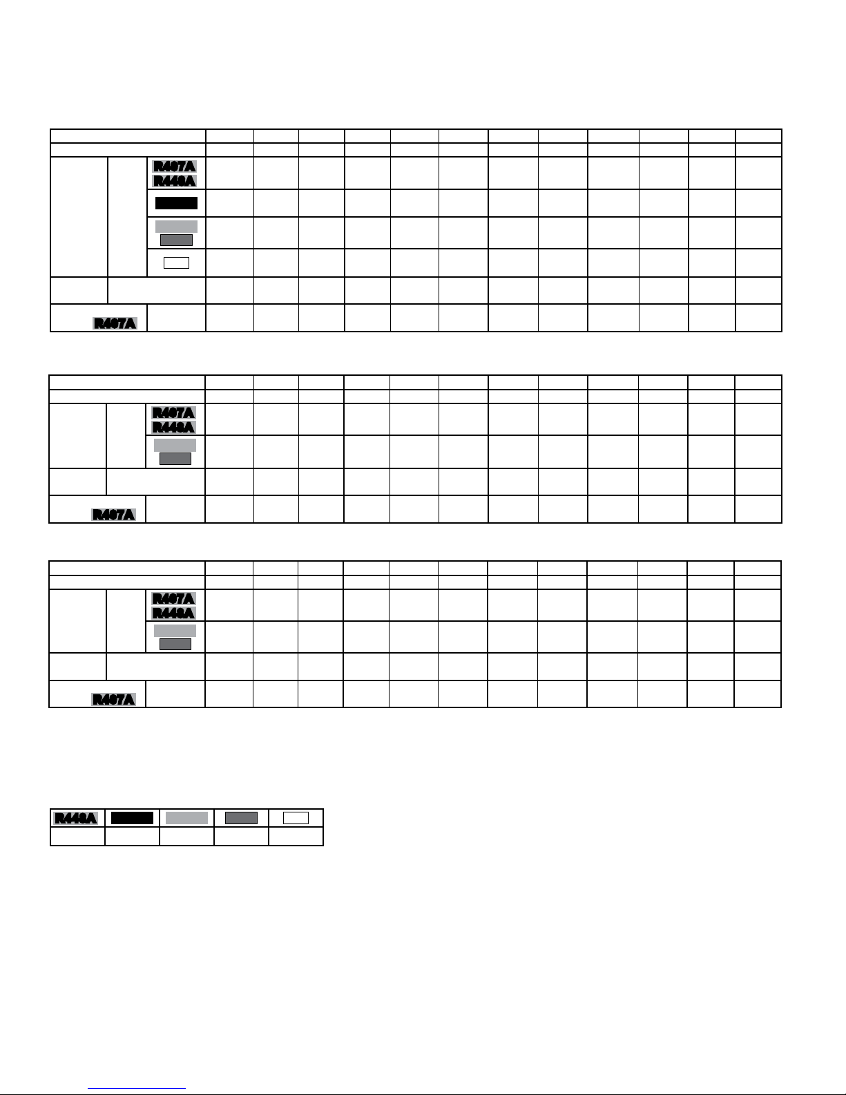
SmartSpeed
Evaporators
EVAP w/ PSC
EVAP with SmartSpeed
REFRIGERATION = FULL SPEED = 60W PER MOTOR
OFF CYCLE = LOW SPEED = 13W PER MOTOR
40 % EXTRA ENERGY SAVINGS vs. FIXED SPEED EC MOTOR ON EVAPORATOR
10 % EXTRA ENERGY SAVINGS ON COMPRESSOR WHEN USING SMARTSPEED EVAPORATOR
DESIGN HIGHLIGHTS
NO COMPLEX CONTROLS, NO COST ADDER, SIMPLE TO UNDERSTAND
PATENT
PENDING
TPLP
29/11/18
T30-TPLP-PDI-14
- 16 -
ECM
60Hz
US Patents Nos.
8,635,883
DESIGN FEATURES
• Standard on all EC Motors
& 9,151,525
• Refrigeration mode – EC motor operates at full speed.
• O Cycle mode – EC motor operates at reduced speed.
• NO special controls required.
Consumption 60 W per motor
Consumption 13 W per motor.
• Energy saving benet on motor and compressor wattage consumption:
20000
18000
16000
14000
12000
with PSC vs ECM vs SmartSpeed Evaporator Fan Motors
ENERGY CONSUMPTION COMPA RISON:
Compressor w/ PSC
Compressor w/ ECM
Compressor w/ SmartSpeed
10000
8000
ADDITIONAL ENERGY SAVINGS WHEN
USING SMARTSPEED EVAPS
6000
4000
Energy Consumption (Watt-Hours)
2000
0
0 50 100 150 200 250 300 350 400 450 500
Time (minutes)
Note: Data collected on a typical freezer application with a 3HP low temp condensing unit and a 4 fan TPLP evaporator
EVAP w/ ECM
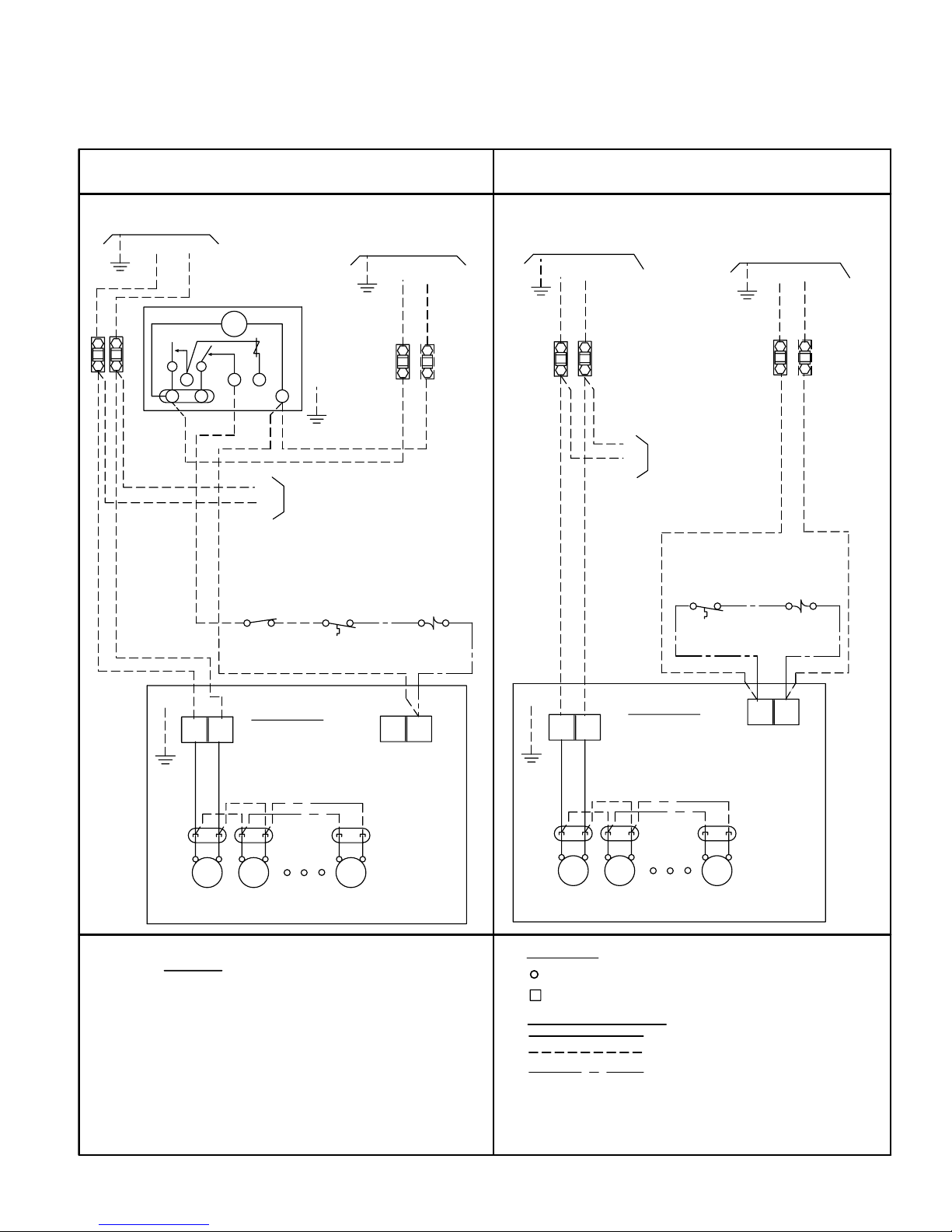
INSTALLATION NOTES
EC motors are factory wired for SmartSpeed operation on evaporators equipped with
a factory installed thermostat.
Page 17

TPLP
29/11/18
T30-TPLP-PDI-14
- 17 -
WIRING DIAGRAM - 115/1/60, 208-230/1/60
OPTIONAL EC MOTORS with
AIR DEFROST MODELS
ECM
60Hz
Page 18
TPLP
29/11/18
T30-TPLP-PDI-14
- 18 -
WIRING DIAGRAM - 208-230/1/60
OPTIONAL EC MOTORS with
ELECTRIC DEFROST MODELS
ECM
60Hz
Page 19

TPLP
29/11/18
T30-TPLP-PDI-14
- 19 -
WIRING DIAGRAM - 208-230/1/60
OPTIONAL EC MOTORS with
ELECTRIC DEFROST MODELS - MULTIPLE EVAPORATORS
ECM
60Hz
Page 20

TPLP 60Hz
29/11/18
T30-TPLP-PDI-14
- 20 -
INTUITIVE EVAPORA T OR CONTROL TECHNOLOGY
What is ESP+?
Trenton Refrigeration's ESP+ intuitive evaporator control technology is designed to replace traditional electromechanical refrigeration controls typically used on medium and low temperature applications. By combining award
winning adaptive technology along with an electronic expansion valve, Trenton Refrigeration continues Leading
The Way with innovative, state-of-the-art designs.
Installing an evaporator utilizing the ESP+ intuitive evaporator control technology is simple. Two pipes, two wires
and you’re done. No interconnecting control wiring between the evaporator and the condensing unit is required.
• Quick simple installation
• Improved evaporator performance by minimizing excessive frost on the evaporator
• Eliminates ice build up on surfaces and product
• Energy savings through evaporator fan management
• Energy savings with reduction in the number of defrost cycles
• Defrost heater management
• Improved system diagnostics and service through advanced alarm notication text/email
• Remote monitoring & system control
• User friendly interface
• Precise temperature control for prolonged product shelf life
• Improved product integrity with less potential for spoilage
• Downloadable data provides system history for prior 30 days
• Remotely view and change system parameters and alarm settings
• Manually control system
• Easily troubleshoot issues
ESP+ controls:
- Box Temperature - Superheat
- Defrost Initiation - Defrost Termination - Fan Motors
- Defrost Heater (Electric Defrost Models)
Plus - User can access operating data directly from the system interface
15-20% System Energy Savings
over a Properly Commissioned System!
86% Fewer Defrost Cycles*
• Enhanced system performance
• Energy Savings
• Improved product integrity
* Data may vary depending on application
Visit t-rp.com/esp for details
Page 21

TPLP 60Hz
29/11/18
T30-TPLP-PDI-14
- 21 -
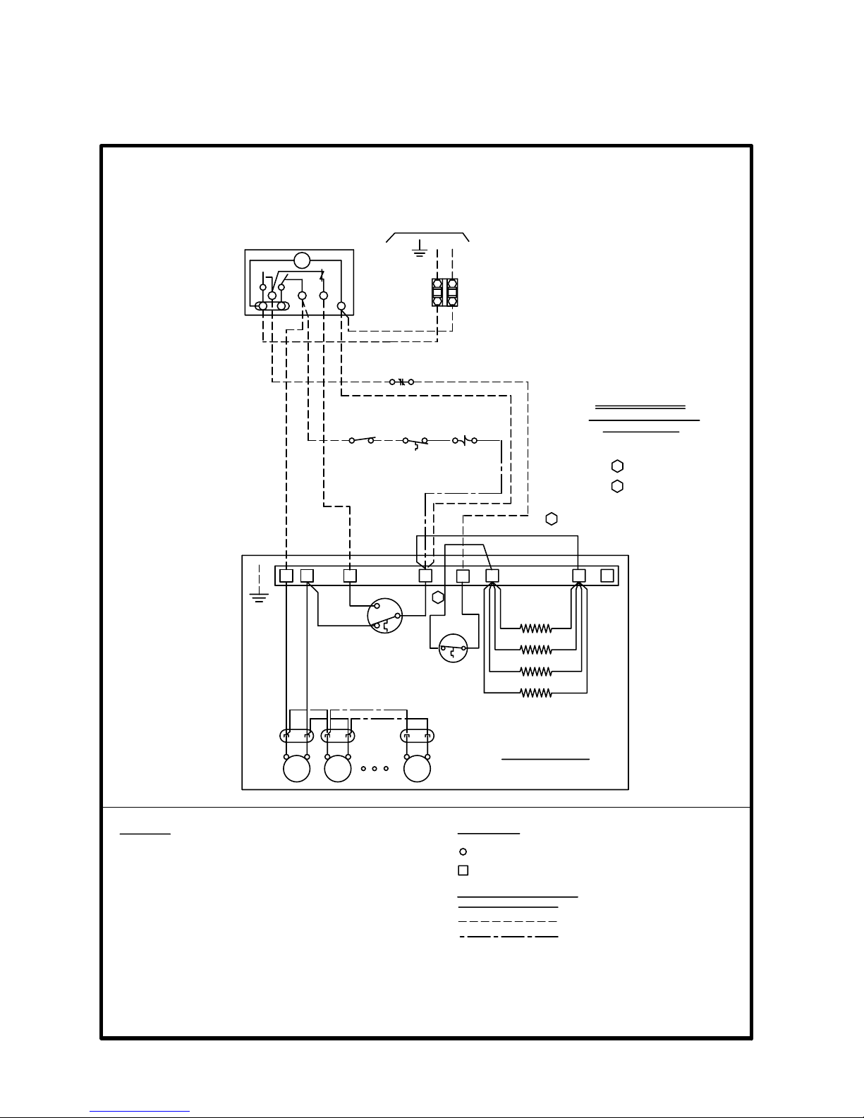
WIRING DIAGRAM - 115/1/60
AIR DEFROST MODELS w/
Page 22

TPLP 60Hz
29/11/18
T30-TPLP-PDI-14
- 22 -
WIRING DIAGRAM - 208-230/1/60
AIR DEFROST MODELS w/
Page 23

TPLP 60Hz
29/11/18
T30-TPLP-PDI-14
- 23 -
WIRING DIAGRAM - 208-230/1/60
1-3 FAN ELECTRIC DEFROST MODELS
w/ MAX. 12A
Page 24

TPLP 60Hz
29/11/18
T30-TPLP-PDI-14
- 24 -
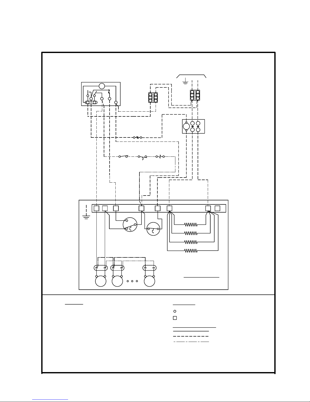
WIRING DIAGRAM - 208-230/1/60
4-5 FAN ELECTRIC DEFROST MODELS
w/ 16A TO 20A
Page 25

TPLP 60Hz
29/11/18
T30-TPLP-PDI-14
- 25 -
WIRING DIAGRAM - 208-230/1/60
6 FAN ELECTRIC DEFROST MODELS
w/ 24A
Page 26

TPLP 60Hz
29/11/18
T30-TPLP-PDI-14
- 26 -
SHIPPING WEIGHTS
Air Defrost Models
MODEL
TPLP
104MA 45 (20)
106MA 47 (21)
107MA 49 (22)
209MA 70 (32)
211MA 74 (33)
214MA 78 (35)
317MA 101 (46)
320MA 107 (48)
423MA 117 (53)
426MA 135 (61)
532MA 163 (74)
639MA 192 (87)
SHIPPING WEIGHT
LB. (kg)
Electric Defrost Models
MODEL
TPLP
104ME 104LE 103VE 49 (22)
106ME 105LE 104VE 51 (23)
107ME 106LE 105VE 53 (24)
209ME 207LE 206VE 76 (34)
211ME 209LE 208VE 80 (36)
214ME 211LE 209VE 84 (38)
317ME 314LE 312VE 109 (49)
320ME 317LE 315VE 115 (52)
423ME 419LE 416VE 127 (58)
426ME 422LE 419VE 145 (66)
532ME 527LE 523VE 176 (80)
639ME 631LE 627VE 207 (94)
SHIPPING WEIGHT
LB. (kg)
Page 27

.438 SLOTS IN
MOUNTING BRACKETS
AIR THROW
APPROX 35'
IN OPEN
SPACE
12
MINIMUM
11 7/83 1/8
3
[305][302] [79]
[76]
[403]
15 7/8
[35]
1 3/8
3/4 MPT / 3/4 FLARE
DRAIN CONNECTION
4, 5 AND 6 FAN
MODELS.
6 1/2
C
A
B
[165]
MTG SLOTS
13 7/16
[341]
(TOP VIEW)
REFRIGERATION
CONNECTIONS.
SUCTION & LIQUID.
ELECTRICAL
CONNECTIONS.
A
B
13 7/16
MTG SLOTS
[165]
[165]
6 1/26 1/2
4
TYP
[102]
[341]
1, 2 AND 3 FAN
MODELS.
(TOP VIEW)
TPLP 60Hz
29/11/18
T30-TPLP-PDI-14
- 27 -
DIMENSIONAL DATA
MODEL
TPLP
NO. OF
FANS
A B C
IN (mm) IN (mm) IN (mm)
104M^ 1 30 1/4 (768) 17 1/4 (438) N/A N/A 5/8 3/8 3/8 3/8
106M^ 1 30 1/4 (768) 17 1/4 (438) N/A N/A 5/8 3/8 3/8 3/8
107M^ 1 30 1/4 (768) 17 1/4 (438) N/A N/A 5/8 3/8 3/8 3/8
209M^ 2 46 1/4 (1175) 33 1/4 (845) N/A N/A 7/8 3/8 3/8 3/8
211M^ 2 46 1/4 (1175) 33 1/4 (845) N/A N/A 7/8 3/8 3/8 3/8
214M^ 2 46 1/4 (1175) 33 1/4 (845) N/A N/A 7/8 3/8 3/8 3/8
317M^ 3 62 1/4 (1581) 49 1/4 (1251) N/A N/A 7/8 3/8 3/8 3/8
320M^ 3 62 1/4 (1581) 49 1/4 (1251) N/A N/A 7/8 3/8 3/8 3/8
423M^ 4 78 1/4 (1988) 32 5/8 (829) 32 5/8 (829) 1 1/8 3/8 3/8 3/8
426M^ 4 78 1/4 (1988) 32 5/8 (829) 32 5/8 (829) 1 1/8 3/8 1/2 3/8
532M^ 5 94 1/4 (2394) 32 5/8 (829) 48 5/8 (1235) 1 3/8 1/2 1/2 1/2
639M^ 6 110 1/4 (2800) 48 5/8 (1235) 48 5/8 (1235) 1 3/8 1/2 1/2 1/2
104L^ 1 30 1/4 (768) 17 1/4 (438) N/A N/A 5/8 3/8 3/8 3/8
105L^ 1 30 1/4 (768) 17 1/4 (438) N/A N/A 5/8 3/8 3/8 3/8
106L^ 1 30 1/4 (768) 17 1/4 (438) N/A N/A 5/8 3/8 3/8 3/8
207L^ 2 46 1/4 (1175) 33 1/4 (845) N/A N/A 7/8 3/8 3/8 3/8
209L^ 2 46 1/4 (1175) 33 1/4 (845) N/A N/A 7/8 3/8 3/8 3/8
211L^ 2 46 1/4 (1175) 33 1/4 (845) N/A N/A 7/8 3/8 3/8 3/8
314L^ 3 62 1/4 (1581) 49 1/4 (1251) N/A N/A 7/8 3/8 3/8 3/8
317L^ 3 62 1/4 (1581) 49 1/4 (1251) N/A N/A 1 1/8 3/8 3/8 3/8
419L^ 4 78 1/4 (1988) 32 5/8 (829) 32 5/8 (829) 1 1/8 3/8 3/8 3/8
422L^ 4 78 1/4 (1988) 32 5/8 (829) 32 5/8 (829) 1 1/8 3/8 3/8 3/8
527L^ 5 94 1/4 (2394) 32 5/8 (829) 48 5/8 (1235) 1 3/8 3/8 1/2 1/2
631L^ 6 110 1/4 (2800) 48 5/8 (1235) 48 5/8 (1235) 1 3/8 1/2 1/2 1/2
103V^ 1 30 1/4 (768) 17 1/4 (438) N/A N/A 5/8 3/8 3/8 3/8
104V^ 1 30 1/4 (768) 17 1/4 (438) N/A N/A 5/8 3/8 3/8 3/8
105V^ 1 30 1/4 (768) 17 1/4 (438) N/A N/A 5/8 3/8 3/8 3/8
206V^ 2 46 1/4 (1175) 33 1/4 (845) N/A N/A 7/8 3/8 3/8 3/8
208V^ 2 46 1/4 (1175) 33 1/4 (845) N/A N/A 7/8 3/8 3/8 3/8
209V^ 2 46 1/4 (1175) 33 1/4 (845) N/A N/A 7/8 3/8 3/8 3/8
312V^ 3 62 1/4 (1581) 49 1/4 (1251) N/A N/A 7/8 3/8 3/8 3/8
315V^ 3 62 1/4 (1581) 49 1/4 (1251) N/A N/A 1 1/8 3/8 3/8 3/8
416V^ 4 78 1/4 (1988) 32 5/8 (829) 32 5/8 (829) 1 1/8 3/8 3/8 3/8
419V^ 4 78 1/4 (1988)
523V^ 5 94 1/4 (2394) 32 5/8 (829) 48 5/8 (1235) 1 3/8 3/8 1/2 1/2
627V^ 6 110 1/4 (2800) 48 5/8 (1235) 48 5/8 (1235) 1 3/8 3/8 1/2 1/2
A or E. Refer to Nomenclature for details
^ =
SUCTION
LIQUID CONNECTION (ID) SWEAT
CONNECTION
(ID) SWEAT
32 5/8 (829) 32 5/8 (829) 1 1/8 3/8 3/8 3/8
R407A
R22
R404A
Page 28

TPLP 60Hz
29/11/18
T30-TPLP-PDI-14
- 28 -
F ACT ORY INST ALLED
EXPANSION V ALVE SELECTIONS -
MEDIUM TEMP. MODELS (MECHANICAL)
MEDIUM TEMPERATURE
R404A
AIR OR ELECTRIC DEFROST
MODEL
TPLP
104M***BR6 N/A EBQE-AA-SC E3 MKC-1
106M***BR6 L-1/2 EBQE-A-SC E3 MKC-1
107M***BR6 L-1/2 EBQE-A-SC E3 MKC-1
209M***BR6 L-3/4 EBQE-A-SC E3 MKC-1
211M***BR6 L-1 EBQE-A-SC E3 MKC-1
214M***BR6 L-1 EBQE-B-SC E5 MKC-1
317M***BR6 L-1 1/2 EBQE-B-SC E5 MKC-1
320M***BR6 L-1 1/2 EBQE-B-SC E5 MKC-1
423M***BR6 L-2 EBQE-C-SC E6 MKC-1
426M***BR6 L-2 EBQE-C-SC E6 MKC-1
532M***BR6 L-2 1/2 EBSSE-6-SC E6 MKC-1
639M***BR6 G-3 EBSSE-6-SC E6 MKC-1
*** Insert defrost and voltage type. See nomenclature for details
FACTORY
INSTALLED
NOZZLE
FACTORY
INSTALLED
EXPANSION
VALVE
FACTORY
INSTALLED
LIQUID LINE
SOLENOID
VALVE
FACTORY
INSTALLED
SOLENOID
COIL
MEDIUM TEMPERATURE
R448A
R407A
R407C
R22
AIR OR ELECTRIC DEFROST
MODEL
TPLP
104M***BR2 N/A EBQE-AAA-VC E3 MKC-1
106M***BR2 L-1/2 EBQE-AA-VC E3 MKC-1
107M***BR2 L-1/2 EBQE-AA-VC E3 MKC-1
209M***BR2 L-3/4 EBQE-A-VC E3 MKC-1
211M***BR2 L-1 EBQE-A-VC E3 MKC-1
214M***BR2 L-1 EBQE-A-VC E3 MKC-1
317M***BR2 L-1 1/2 EBQE-A-VC E3 MKC-1
320M***BR2 L-1 1/2 EBQE-B-VC E5 MKC-1
423M***BR2 L-2 EBQE-B-VC E5 MKC-1
426M***BR2 L-2 EBQE-B-VC E5 MKC-1
532M***BR2 L-2 1/2 EBQE-C-VC E6 MKC-1
639M***BR2 G-3 EBQE-C-VC E6 MKC-1
*** Insert defrost and voltage type. See nomenclature for details
FACTORY
INSTALLED
NOZZLE
FACTORY
INSTALLED
EXPANSION
VALVE
FACTORY
INSTALLED
LIQUID LINE
SOLENOID
VALVE
FACTORY
INSTALLED
SOLENOID
COIL
Page 29

TPLP 60Hz
29/11/18
T30-TPLP-PDI-14
- 29 -
F ACT ORY INST ALLED
EXPANSION V ALVE SELECTIONS -
LOW TEMP. MODELS (MECHANICAL)
LOW TEMPERATURE
R404A
ELECTRIC DEFROST
MODEL
TPLP
104LE**BR6 L-1/2 EBQE-AA-ZP E3 MKC-1
105LE**BR6 L-3/4 EBQE-AA-ZP E3 MKC-1
106LE**BR6 L-1 EBQE-A-ZP E3 MKC-1
207LE**BR6 L-1 EBQE-A-ZP E3 MKC-1
209LE**BR6 L-1 1/2 EBQE-A-ZP E3 MKC-1
211LE**BR6 L-2 EBQE-B-ZP E3 MKC-1
314LE**BR6 L-2 EBQE-B-ZP E5 MKC-1
317LE**BR6 L-3 EBQE-C-ZP E5 MKC-1
419LE**BR6 L-3 EBQE-C-ZP E5 MKC-1
422LE**BR6 G-4 EBQE-C-ZP E6 MKC-1
527LE**BR6 G-4 EBSSE-6-ZP E6 MKC-1
631LE**BR6 G-5 EBSSE-6-ZP E6 MKC-1
*** Insert voltage type. See nomenclature for details
FACTORY
INSTALLED
NOZZLE
FACTORY
INSTALLED
EXPANSION
VALVE
FACTORY
INSTALLED
LIQUID LINE
SOLENOID
VALVE
FACTORY
INSTALLED
SOLENOID
COIL
LOW TEMPERATURE
R404A
ELECTRIC DEFROST 4 FPI
MODEL
TPLP
103VE**BR6 L-1/2 EBQE-AA-ZP E3 MKC-1
104VE**BR6 L-3/4 EBQE-AA-ZP E3 MKC-1
105VE**BR6 L-1 EBQE-A-ZP E3 MKC-1
206VE**BR6 L-1 EBQE-A-ZP E3 MKC-1
208VE**BR6 L-1 1/2 EBQE-A-ZP E3 MKC-1
209VE**BR6 L-2 EBQE-B-ZP E3 MKC-1
312VE**BR6 L-2 EBQE-B-ZP E5 MKC-1
315VE**BR6 L-3 EBQE-C-ZP E5 MKC-1
416VE**BR6 L-3 EBQE-C-ZP E5 MKC-1
419VE**BR6 G-4 EBQE-C-ZP E6 MKC-1
523VE**BR6 G-4 EBQE-C-ZP E6 MKC-1
627VE**BR6 G-5 EBSSE-6-ZP E6 MKC-1
*** Insert voltage type. See nomenclature for details
FACTORY
INSTALLED
NOZZLE
FACTORY
INSTALLED
EXPANSION
VALVE
FACTORY
INSTALLED
LIQUID LINE
SOLENOID
VALVE
FACTORY
INSTALLED
SOLENOID
COIL
LOW TEMPERATURE
R448A
R407A
R22
ELECTRIC DEFROST
MODEL
TPLP
104LE**BR2 L-1/2 EBQE-AA-VZ E3 MKC-1
105LE**BR2 L-3/4 EBQE-AA-VZ E3 MKC-1
106LE**BR2 L-1 EBQE-AA-VZ E3 MKC-1
207LE**BR2 L-1 EBQE-A-VZ E3 MKC-1
209LE**BR2 L-1 1/2 EBQE-A-VZ E3 MKC-1
211LE**BR2 L-2 EBQE-A-VZ E3 MKC-1
314LE**BR2 L-2 EBQE-B-VZ E3 MKC-1
317LE**BR2 L-3 EBQE-B-VZ E5 MKC-1
419LE**BR2 L-3 EBQE-B-VZ E5 MKC-1
422LE**BR2 G-4 EBQE-C-VZ E5 MKC-1
527LE**BR2 G-4 EBQE-C-VZ E5 MKC-1
631LE**BR2 G-5 EBQE-C-VZ E6 MKC-1
*** Insert voltage type. See nomenclature for details
FACTORY
INSTALLED
NOZZLE
FACTORY
INSTALLED
EXPANSION
VALVE
FACTORY
INSTALLED
LIQUID LINE
SOLENOID
VALVE
FACTORY
INSTALLED
SOLENOID
COIL
LOW TEMPERATURE
R448A
R407A
R22
ELECTRIC DEFROST 4 FPI
MODEL
TPLP
103VE**BR2 L-1/2 EBQE-AAA-VZ E3 MKC-1
104VE**BR2 L-3/4 EBQE-AA-VZ E3 MKC-1
105VE**BR2 L-1 EBQE-AA-VZ E3 MKC-1
206VE**BR2 L-1 EBQE-A-VZ E3 MKC-1
208VE**BR2 L-1 1/2 EBQE-A-VZ E3 MKC-1
209VE**BR2 L-2 EBQE-A-VZ E3 MKC-1
312VE**BR2 L-2 EBQE-B-VZ E3 MKC-1
315VE**BR2 L-3 EBQE-B-VZ E5 MKC-1
416VE**BR2 L-3 EBQE-B-VZ E5 MKC-1
419VE**BR2 G-4 EBQE-C-VZ E5 MKC-1
523VE**BR2 G-4 EBQE-C-VZ E5 MKC-1
627VE**BR2 G-5 EBQE-C-VZ E6 MKC-1
*** Insert voltage type. See nomenclature for details
FACTORY
INSTALLED
NOZZLE
FACTORY
INSTALLED
EXPANSION
VALVE
FACTORY
INSTALLED
LIQUID LINE
SOLENOID
VALVE
FACTORY
INSTALLED
SOLENOID
COIL
Page 30

TPLP 60Hz
29/11/18
T30-TPLP-PDI-14
- 30 -
F ACT ORY INST ALLED
EXPANSION V ALVE SELECTIONS -
MODELS w/
MEDIUM TEMPERATURE
R448A
R407A
AIR OR ELECTRIC DEFROST
MODEL
TPLP
104M***BR8-ESP N/A 9 E3
106M***BR8-ESP L1/2 11 E3
107M***BR8-ESP L1/2 14 E3
209M***BR8-ESP L3/4 14 E3
211M***BR8-ESP L1 14 E3
214M***BR8-ESP L1 18 E3
317M***BR8-ESP L1-1/2 18 E5
320M***BR8-ESP L1-1/2 24 E5
423M***BR8-ESP L2 24 E5
426M***BR8-ESP L2 24 E5
532M***BR8-ESP L2-1/2 35 E6
639M***BR8-ESP G3 35 E6
*** Insert defrost and voltage type. See nomenclature for details
FACTORY
INSTALLED
NOZZLE
R407C R404A
FACTORY
INSTALLED
E2V EXPANSION
VALVE
R22
FACTORY
INSTALLED
LIQUID LINE
SOLENOID VALVE
LOW TEMPERATURE
R448A
R407A
R404A
R22
ELECTRIC DEFROST
MODEL
TPLP
104LE**BR8-ESP L1/2 9 E3
105LE**BR8-ESP L3/4 9 E3
106LE**BR8-ESP L1 11 E3
207LE**BR8-ESP L1 11 E3
209LE**BR8-ESP L1-1/2 11 E3
211LE**BR8-ESP L2 14 E3
314LE**BR8-ESP L2 14 E5
317LE**BR8-ESP L3 18 E5
419LE**BR8-ESP L3 18 E5
422LE**BR8-ESP G4 24 E5
527LE**BR8-ESP G4 24 E6
631LE**BR8-ESP G5 24 E6
** Insert voltage type. See nomenclature for details
FACTORY
INSTALLED
NOZZLE
FACTORY
INSTALLED
E2V EXPANSION
VALVE
FACTORY
INSTALLED
LIQUID LINE
SOLENOID VALVE
LOW TEMPERATURE
R448A
R407A
R404A
R22
ELECTRIC DEFROST 4 FPI
MODEL
TPLP
103VE**BR8-ESP L1/2 9 E3
104VE**BR8-ESP L3/4 9 E3
105VE**BR8-ESP L1 9 E3
206VE**BR8-ESP L1 11 E3
208VE**BR8-ESP L1-1/2 11 E3
209VE**BR8-ESP L2 11 E3
312VE**BR8-ESP L2 14 E3
315VE**BR8-ESP L2-1/2 14 E5
416VE**BR8-ESP J2-1/2 18 E5
419VE**BR8-ESP G3 18 E5
523VE**BR8-ESP G4 24 E5
627VE**BR8-ESP G5 24 E6
** Insert voltage type. See nomenclature for details
FACTORY
INSTALLED
NOZZLE
FACTORY
INSTALLED
E2V EXPANSION
VALVE
FACTORY
INSTALLED
LIQUID LINE
SOLENOID VALVE
Page 31

TPLP 60Hz
29/11/18
T30-TPLP-PDI-14
- 31 -
INSTALLATION INSTRUCTIONS
INSTALLATION
The installation and start-up of evaporators should only
be performed by qualied refrigeration mechanics.
This equipment should be installed in accordance with
all applicable codes, ordinances and local by-laws.
INSPECTION
Inspect all equipment before unpacking for visible signs
of damage or loss. Check shipping list against material
received to ensure shipment is complete.
IMPORTANT: Remember, you, the consignee, must
make any claim necessary against the transportation
company. Shipping damage or missing parts, when
discovered at the outset, will prevent later unnecessary
and costly delays.
If damage or loss during transport is evident, make
claim to carrier, as this will be their responsibility,
not the manufacturer’s.
Should carton be damaged, but damage to equipment is
not obvious, a claim should be led for “concealed
damage” with the carrier.
IMPORTANT: The electrical characteristics of the unit
should be checked at this time to make sure they
correspond to those ordered and to electrical power
available at the job site.
Save all shipping papers, tags and instruction sheets for
reference by installer and owner.
APPLICATION
TPLP evaporators are designed for walker-in cooler and
freezer applications used with a wide range of refrigerants. For room temperatures above 35°F (2°C) AND
evaporating temperatures above 26°F (-3°C), positive
defrosting means (electric) may not be required,
otherwise, electric defrost defrost models should be
used. Electric defrost models come with defrost
termination and fan delay as standard to control the
defrost cycle termination and fan delay, while defrost
initiation means (e.g. defrost timer) is not included.
The coil must not be exposed to any abnormal
atmospheric or acidic environments. This may result in
corrosion to the cabinet and possible coil failure (leaks).
LOCATION
The unit location in the room should be selected to ensure uniform air distribution throughout the entire space
to be refrigerated. Be sure that the product does not
obstruct the free circulation of air. Allow a minimum of
24” clearance at each end. Do not locate evaporators
over doors. Consideration should be given to the coil
location in order to minimize the piping run length to the
condensing unit and oor drain.
EXPANSION VALVE (TXV) PRE-SELECTED
Locate the expansion valve bulb on a horizontal
length of suction line preferably 3 to 6 inches
from the suction header. Locate the bulb at 4 or
8 clock position and insulate with a waterproof
type of insulation. Clamp the bulb to ensure
100% contact of the bulb with the suction line.
After following the manufacturer’s installation instructions
and after the room has reached the desired
temperature the valve superheat should be checked.
This will conrm that the evaporator is operating
properly and performing to maximum eciency. The
superheat should be around 6 (3.3°C) to 8°F (4.4°C) for
a 10 to 12°F T.D (5.6 to 6.7°C). Too high or low a super
heat will result in unsatisfactory system
performance and possible compressor problems.
MOUNTING
Refer to dimensional drawing for recommended
mounting arrangements. Ensure adequate clearance
is provided behind the coil as well as each end. The
evaporators may be mounted ush with ceiling with
bolts, or hanging down with rod hangers. When using
rod hangers, allow adequate space between the top of
the unit and the ceiling for cleaning to comply with NSF
Standard 7.
Ensure that the ceiling is level since the drain pan
has been sloped for drainage during the defrost
cycle.
DRAIN LINE
The drain line should be run from the drain connection,
sloping at least 1” (25 mm) per foot and should have
the size at least as large as the drain connection. A
P-Trap in a warm area outside the room must be
provided to allow proper draining through the tubing.
Connection should be made to proper drainage facilities
that comply with local regulations.
To prevent freeze-up when the temperature of the
refrigerated space is 35°F (2°C) or lower, the drain line
should be heated along its run inside the cold room.
The heated drain line should be insulated. It is recommended that the heater be energized at all times. A
heat input of 20 watts per foot in a 28°F (-2°C) room
and 30 watts per foot for -20°F (-29°C) rooms, is
satisfactory. Drain line heaters are not required for
constant room temperature above 35°F (2°C).
Always trap evaporator drain line individually to prevent
vapor migration.
Ensure that the drain line has sucient slope for
proper drainage (prevention of ice build up/blockage in pan).
Page 32

TPLP 60Hz
29/11/18
T30-TPLP-PDI-14
- 32 -
INSTALLATION INSTRUCTIONS (cont’d)
PIPING
Refrigeration grade piping must be used for all eld
refrigeration piping. Refrigerant line sizes are important
and may not be the same size as the coil connections.
Consult ASHRAE handbook or other similar reference
book for proper line sizing.
Refrigerant piping and control system should be designed
to prevent possible liquid slugging (from oil or refrigerant)
of the compressors on start-up after the defrost cycle.
Also, it should prevent oil logging and minimize refrigerant
pressure drop.
WIRING
Wire system in accordance with governing standards and
local codes. See data and wiring diagrams on pages 4 to
20 for typical wiring arrangement. Electrical wiring is to be
sized in accordance with minimum circuit ampacity rating
(MCA). Size fuses used must not exceed the Maximum
Fuse Size ratings.
For ease of identifying the proper wiring terminal, unit
wiring is color coded and terminal block connections are
identied.
When fan delay thermostats (combination fan delay and
defrost termination) are installed, on start-up, the fans
do not operate until the coil temperature is reduced to
approximately 25oF (-4°C). It is normal for the fans to
cycle a few times until the room temperature is brought
down. At higher evaporating temperatures this control
may not close and therefore should either be by-passed
temporarily or replaced with an adjustable type. (set for a
higher temperature cut-in point).
MAINTENANCE
The unit should be periodically inspected for any dirt or ice
build-up on the n surface and cleaned if necessary with
a soft whisk or brush. Also ensure coils inner (and outer)
drain pans do not have any ice build-up from improper
defrost operation. When replacing heater elements rst
remove heater retainer brackets and heater clips.
SYSTEM CHECK
Before Start-Up:
1. All wiring should be in accordance with local
codes.
2. Refrigerant lines should be properly sized.
3. Thorough evacuation and dehydration has been
performed.
4. The suction, discharge, and receiver service
valves must be open.
5. The system preferably include a liquid line lter
drier moisture indicator and suction lter.
6. Pour enough water into the drain pan to allow a
good check on drainage and seal the trap.
After Start-Up:
1. Check the oil level to be sure the oil charge is
correct.
2. On initial start up the fans do not start until coil
temperature is pulled down to approximately 25°F
(-4°C) on the coil. Also, it is normal for the fan to
cycle a few times until the room temperature is
pulled down.
3. If necessary, temporarily by-pass fan delay control
(to run fans until room temp is lowered).
4. Be sure that the expansion valve is properly set to
provide the correct amount of superheat.
5. After the box temperature is close to reaching the
desired temperature, the evaporator superheat
must be checked and adjustment made if
necessary. In general, evaporators running with
a TD of 10°F (5.6°C ) should have a superheat
reading of 6° to 8°F (3.3°C to 4.4°C). For
evaporators with another T.D., the general rule is
that the superheat should be around 60 to
80% of T .D.
6. Heavy moisture loads are usually encountered
when starting the system for the rst time.
This may cause a rapid build-up of frost on the
evaporator. During the initial pull down, we
suggest that the frost build-up be watched and
defrosted manually as required.
7. Observe that the system goes through at least
one complete DEFROST CYCLE.
Visit
t-rp.com/esp
for Quick Start Guide, Operation Manual, etc
Page 33

TPLP 60Hz
29/11/18
T30-TPLP-PDI-14
- 33 -
NOTES
Page 34

TPLP 60Hz
29/11/18
T30-TPLP-PDI-14
- 34 -
System
Model Number Date of Start-Up
Serial Number Service Contractor
Refrigerant Phone
Electrical Supply E-Mail
PROJECT INFORMATION
Page 35

TPLP 60Hz
29/11/18
T30-TPLP-PDI-14
- 35 -
PRODUCT SUPPORT RESOURCES
web: t-rp.com/tplp
email: evaps@t-rp.com
call: 1-844-893-3222 x520
email: troubleshooting@t-rp.com
call: 1-844-893-3222 x529
web: t-rp.com/parts
email: parts@t-rp.com
call: 1-844-893-3222 x520
web: t-rp.com/warranty
email: warranty@t-rp.com
call: 1-844-893-3222 ext. 501
email: orders@t-rp.com
call: 1-844-893-3222 x501
email: shipping@t-rp.com
call: 1-844-893-3222 x503
Page 36

“AS BUILT” SERVICE PARTS LIST
29/11/18
Service Parts List
Label
To Be Attached
HERE
Trenton Refrigeration
Brantford, ON • Longview, TX
1-800-463-9517 info@t-rp.com www.t-rp.com
Due to the manufacturer’s policy of continuous product improvement, we reserve the right to make changes without notice.
 Loading...