

Page 1
PRODUCT DATA &
01/16/11
INSTALLATION
ONE TO FOUR FAN MODELS
ELECTRICAL POWER:
208-230/1/60, 208-230/3/60,
460/1/60, 460/3/60,
575/1/60, 575/3/60
TFM-LINE
FLUID
COOLERS
Bulletin T60-TFM-PDI
1090825
CONTENTS
Page
Nomenclature............................................. 2
Features & Options.................................... 2
Fluid Cooler Selection................................ 3
Typical Applications.................................... 4
Physical/Mechanical Data (All Models)...... 5
Standard Motors
Electrical Data............................................ 5
Low Ambient Operation.............................. 6
Wiring Diagrams......................................... 7 - 8
EC Motors
About EC Motors........................................ 9
Electrical Data............................................ 9
Wiring Diagram........................................... 10
EC Motor Application Data......................... 11 - 12
Page
Header Sizes (All Models).................. 13
Dimensional Data (All Models)........... 14 - 15
Installation........................................... 16 - 18
Hydronic System Components........... 18 - 19
Pump Package System Parameters... 20
Generic Service Parts......................... 21
Warranty.............................................. 23
Project Information.............................. 23
“As Built” Service Parts List................. BACK
For the latest product updates and further
information, visit www.trentonrefrigeration.com
Page 2

Brand Name:
T60-TFL-PDI
- 2 -
01/16/11
T = Trenton
Product Name
FM = Medium Sized Fluid Cooler
Fans Wide
1 = Inline (Double wide not available)
Fans Deep
Motor
A = 1075 RPM, 3/4 HP Motor
E = ECM Motor
Coil Rows Deep
2, 3, or 4
Coil Fins Per Inch
08 = 8 fpi 10 = 10 fpi 12 = 12 fpi
NOMENCLATURE
T FM 1 3 A - 4 08 V - T5 A - XXXX
Optional Sufx
Does Not Affect Design
Design Version
Voltage
S2 = 208-230/1/60 T3 = 208-230/3/60
S4 = 460/1/60 T4 = 460/3/60
S5 = 575/1/60 T5 = 575/3/60
Application
V = Vertical Air Discharge
H = Horizontal Air Discharge
STANDARD FEATURES INCLUDE
• Heavy-gauge galvanized steel cabinet construction
• Energy efcient PSC and 3 phase fan motors
with internal overload protection
• Quiet “swept wing” fan blade for quiet operation and
optimal efciency
• Heavy duty 24” legs
OPTIONAL FEATURES
• Fan Cycling – Ambient thermostat / fan row
with contactors
• Fan Cycling – Aquastat thermostat fan cycling
control / outlet uid temperature
• Individual fan motor fusing
• Non-fused disconnect
• Horizontal air discharge conguration
• All fan sections individually bafed with
clean-out panels.
• Zinc plated huck bolts
• Control circuit voltage – 230 V
• Variable Speed EC Motor which provides optimum
efciency and sound levels (see pg. 9-12 for details)
• Extended leg kits (36” or 48”) with cross bracing for
extra rigidity
• Optional n materials
• Optional coil coating
• Voltages available for 60Hz or 50Hz
Page 3

FLUID COOLER SELECTION
SAMPLE
T60-TFL-PDI
- 3 -
01/16/11
TFM 60Hz
Previously, the selection of a uid cooler involved using charts, correction factors and hand calculations to
determine the capacity and make the selection.
We have simplied the selection process. Our engineering department has created a computer program.
This provides exibility and streamlines the selection process
TEMPERATURE LIMITATIONS
Fluid Coolers are suitable for leaving air temperatures up to a maximum of 130°F (54°C). Fluid temperature
up to an average of 150°F (66°C ) may be used at ambient temperatures up to 90°F (32°C ). Entering uid
conditions should not exceed 200°F (93°C ).
PARAMETERS FOR SELECTION OF A FLUID COOLER
Fluid Type: □ Water □ Ethylene Glycol / Water
□ Propylene Glycol / Water
Elevation: ___________ Feet Above Sea Level
Fluid Concentration: ___________%Water ___________%Glycol
Air Inlet (ambient temp.) __________ ºF
Three of the four following parameters must be specied:
1. Required Capacity __________ Btu/h 2. Fluid Inlet Temperature __________ ºF
3. Fluid Flow Rate __________ GPM 4. Fluid Outlet Temperature __________ ºF
Other Items To Specify:
1. Voltage (S2 = 208-230/1/60 S4 = 460/1/60 S5 = 575/1/60
T3 = 208-230/3/60 T4 = 460/3/60 T5 = 575/3/60) ______Specify S2,S4, S5,T3,T4 or T5
2. Please Specify (Check Box) Options Required:
Control Voltage 240V (Standard) Variable Speed EC Motor
Control Voltage 120V Extended leg kits 36”
Control Voltage 24V Extended leg kits 48”
Fan Cycling Ambient Thermostat Gold Coat Fin
Fan Cycling Aquastat Thermostat Copper Fin
Fan Cycling Control by Others Heresite Coating
Non-fused disconnect 50 Hz
Horizontal air discharge conguration
Customer Info:
Name: ______________________ Telephone Number: _____________________
Fax: ______________________ Email: ______________________
Fax or email completed sheet to your sales representative.
Extra copies of this form available on page 22
Page 4
TYPICAL APPLICATIONS
p
y
p
T60-TFL-PDI
- 4 -
01/16/11
TFM 60Hz
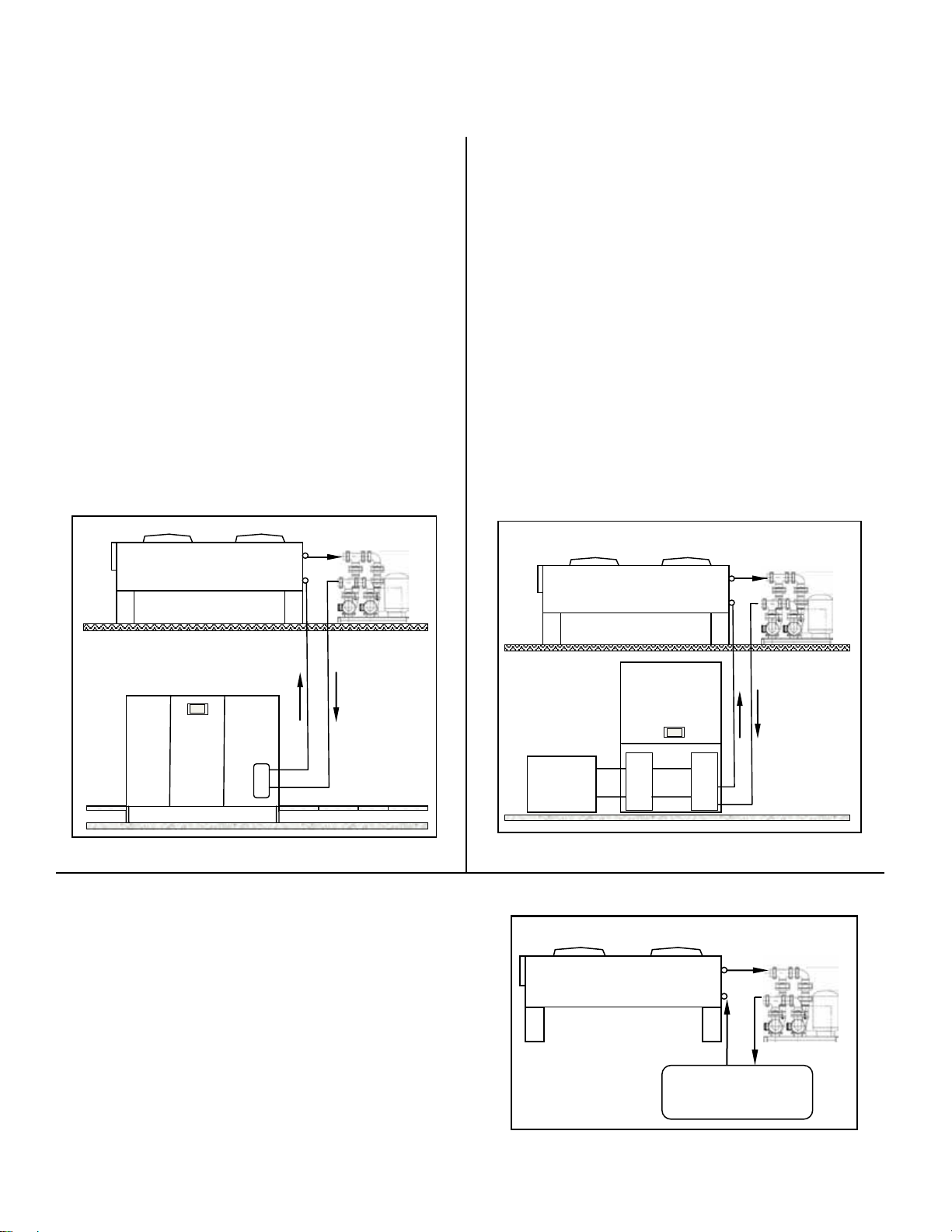
Data Center / Computer Rooms
Fluid Coolers are suitable for use with Computer Room
Air Conditioning (CRAC) Units. (see Illustration below)
Dry Type Fluid Coolers are particularly suitable for applications where long pipe runs of refrigerant piping to
an air cooled condenser are not practical. Cooling Tower
maintenance and winter operation issues are eliminated.
Piping can be easily installed and low ambient control
can be used using water regulating valves. Fluid cooler
can be easily connected to city water for emergency use.
The glycol loop is sometimes connected to a “Free-Cooling” Economizer Coil within the CRAC unit, which allows
for partial free-cooling when the glycol loop temperature
is below the CRAC units return air temperature.
Dual Pump Pkg c/w
ansion Tank
Ex
Dry Fluid Cooler
Industrial Glycol /Water Cooling Systems
Water pollution issues and water conservation have
become critical in recent years. The “Once-Only” use of
water for industrial process cooling has been wasteful
and often unnecessary. By using a dry type Fluid Cooler,
glycol/water for industrial process cooling applications
can be cooled to within 10°F (6°C) of the ambient dry
bulb temperature. The water is continuously re-circulated
and remains in a closed system so reducing the problem
of corrosion normally encountered in non re-circulated
systems.
Considerable savings can be affected by using a Dry
Type Fluid Cooler. Many industrial applications have
seen water consumption being reduced by millions of gallons and reduced maintenance costs to a fraction of that
experienced prior to the use of a closed non re-circulated
system. (see illustration below)
Dual Pump Pkg c/w
ansion Tank
Ex
Dry Fluid Cooler
Computer Room Air
Conditioner( CRAC)U nit
Glycol /
Water
Cooled
Cond.
Computer
Room AC
(CRAC)
Unit
Secondary
Heat
Exchanger
Remote Radiators for Diesel and Gas Engines
A remote radiator is usually required with the larger style
of diesel engine. The Fluid Cooler is suitable for this type
of application. Designed to give the customer trouble free
operation, the multiple fan arrangement reduces the possibility of down time. Units are completely pre-assembled
and require only piping and electrical connections. (see
illustration to the right)
Glycol/Water
Cooled
Cooling
S
stem
Process
Heat
Load
Glycol/Water
Cooled
Chiller
E
V
A
P
C
O
N
D
Cooler
Glycol/Water
Cooled
Cooling
System
Dual Pump Pkg c/w
Dry Fluid Cooler
Expansion Tank
Remote
Radiator
for
Engine
Diesel Engine
for
Page 5
TFM
T60-TFL-PDI
- 5 -
01/16/11
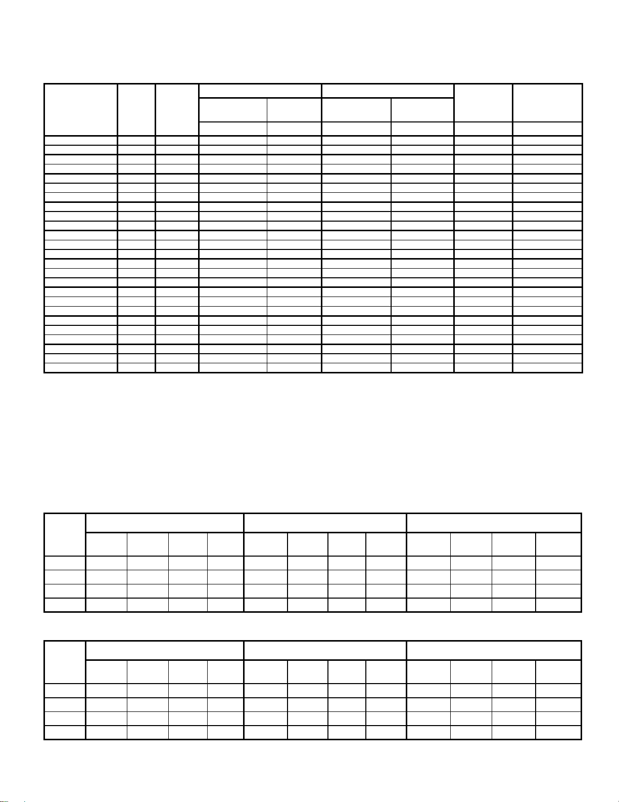
PHYSICAL / MECHANICAL DATA
60Hz
1075 RPM (A) ECM (E)
MODEL
NO.
TFM 11*-310 10 1 x 1 6870
TFM 11*-312 12 1 x 1 6640
TFM 11*-410 10 1 x 1 6620
TFM 11*-412 12 1 x 1 6400
TFM 12*-208 8 1 x 2 14800
TFM 12*-210 10 1 x 2 14400
TFM 12*-212 12 1 x 2 13900
TFM 12*-308 8 1 x 2 14200
TFM 12*-310 10 1 x 2 13700
TFM 12*-312 12 1 x 2 13300
TFM 12*-408 8 1 x 2 13700
TFM 12*-410 10 1 x 2 13200
TFM 12*-412 12 1 x 2 12800
TFM 13*-308 8 1 x 3 21300
TFM 13*-310 10 1 x 3 20600
TFM 13*-312 12 1 x 3 19900
TFM 13*-408 8 1 x 3 20500
TFM 13*-410 10 1 x 3 19900
TFM 13*-412 12 1 x 3 19200
TFM 14*-308 8 1 x 4 28400
TFM 14*-310 10 1 x 4 27500
TFM 14*-312 12 1 x 4 26600
TFM 14*-408 8 1 x 4 27400
TFM 14*-410 10 1 x 4 26500
TFM 14*-412 12 1 x 4 25600
NOTES:
* Insert voltage code (see Nomenclature, page 2)
(1) For 50 HZ fan data, use 60 Hz CFM (m3/h) x 0.83
(2) Sound level pressure at 30 ft (10m)
(3) Not including headers.
FPI
FAN
AIR FLOW
(1)
CONFIG.
RATE
CFM (m3/h) dBA CFM (m3/h) dBA US (LITRES) LBS. (kg.)
11670
11280
11250
10870
25150
24470
23620
24130
23280
22600
23280
22430
21750
36190
35000
33810
34830
33810
32620
48250
46720
45190
46550
45020
43490
SOUND
LEVEL
51 6180
51 5980
51 5960
51 5760
53 13320
53 12960
53 12510
53 12780
53 12330
53 11970
53 12330
53 11880
53 11520
54 19170
54 18540
54 17910
54 18450
54 17910
54 17280
55 25560
55 24750
55 23940
55 24660
55 23850
55 23040
APPROX. DRY
(3)
SHIPPING
WEIGHT
AIR FLOW
(2)
RATE
(1)
10500
10160
10130
9790
22630
22020
21250
21710
20950
20340
20950
20180
19570
32570
31500
30430
31350
30430
29360
43430
42050
40670
41900
40520
39140
SOUND
LEVEL
50 1.9 7.2 245 111
50 1.9 7.2 250 114
50 2.5 9.5 265 120
50 2.5 9.5 270 123
52 2.4 9.1 410 186
52 2.4 9.1 415 189
52 2.4 9.1 420 191
52 3.6 13.6 450 205
52 3.6 13.6 455 207
52 3.6 13.6 460 209
52 4.8 18.2 480 218
52 4.8 18.2 490 223
52 4.8 18.2 500 227
53 5.4 20.4 630 286
53 5.4 20.4 640 291
53 5.4 20.4 650 295
53 7.2 27.3 680 309
53 7.2 27.3 695 316
53 7.2 27.3 710 323
54 7.1 26.9 810 368
54 7.1 26.9 825 375
54 7.1 26.9 840 382
54 9.5 36.0 880 400
54 9.5 36.0 900 409
54 9.5 36.0 920 418
(2)
INTERNAL
VOLUME
ELECTRICAL DATA
1075 RPM MODELS - SINGLE PHASE
NO. OF
FAN
MOTORS
1 3.6 4.5 15.0 790 1.7 2.1 15 810 1.4 1.8 15.0 830
2 7.2 8.1 15.0 1580 3.4 3.8 15 1620 2.8 3.2 15.0 1660
3 10.8 15.1 20.0 2370 5.1 5.5 15 2430 4.2 4.6 15.0 2490
4 14.4 15.3 20.0 3160 6.8 7.2 15 3240 5.6 6.0 15.0 3320
NO. OF
FAN
MOTORS
1 2.3 2.9 15.0 720 1.2 1.4 15 720 0.9 1.1 15.0 720
2 4.6 5.2 15.0 1440 2.3 2.6 15 1440 1.8 2.0 15.0 1440
3 6.9 7.5 15.0 2160 3.5 3.7 15 2160 2.7 2.9 15.0 2160
4 9.2 9.8 15.0 2880 4.6 4.9 15 2880 3.6 3.8 15.0 2880
TOTAL
TOTAL
208-230/1/60 460/1/60 575/1/60
FLA
MCA MOP WATTS
TOTAL
FLA
MCA MOP WATTS
TOTAL
FLA
1075 RPM MODELS - THREE PHASE
208-230/3/60 460/3/60 575/3/60
FLA
MCA MOP WATTS
TOTAL
FLA
MCA MOP WATTS
TOTAL
FLA
MCA MOP WATTS
MCA MOP WATTS
Page 6

TFM
T60-TFL-PDI
- 6 -
01/16/11
LOW AMBIENT OPERATION
60Hz
Fan Cycling Control
When a remote air cooled Fluid Cooler is installed outdoors, it will be subjected to varying temperatures. Within
many areas, winter to summer annual temperature swings
can be as high as 120°F (48.9°C) or so. This will have a
major impact on the performance of the Fluid Cooler. As
the ambient temperature drops, the Fluid Cooler capacity
increases due to a wider temperature difference between
ambient air and entering uid temperature. As this happens, the leaving uid temperature drops as well.
Cycling of the Fluid Cooler fans helps control the leaving
uid temperature. With this approach to solving low ambient problems, fans are taken off-line one at a time. It is not
recommended that multiple fan Fluid Coolers cycle more
than two (2) fans per step. The reason for this is that the
uid temperature will change drastically as several fans
are taken off-line at the same time. This could result in
excessive tube stress within the unit, due to rapid expansion and contraction of the coil which could lead to needless tube failure.
Fan Cycling Control Schedule
Fans closest to the inlet header should be set to run whenever the uid circulating pump is running.
Substantial fan motor power savings can be realized as
well using this method.
For low ambient conditions, optional
Aquastats (Fluid Temperature
Controllers) are used to cycle fans
on and off as required to maintain
constant leaving glycol/water
temperature as per the schedules below.
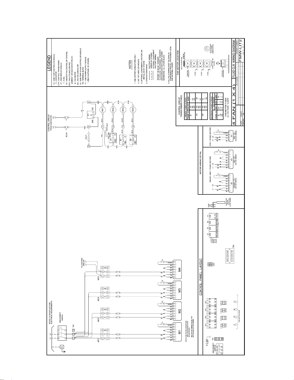
Page 7
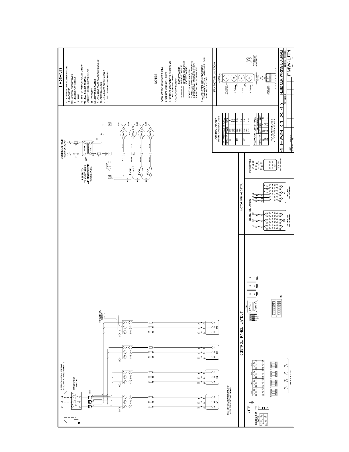
TFM
T60-TFL-PDI
- 7 -
01/16/11
WIRING DIAGRAM
AMBIENT FAN CYCLING
1075 RPM
60Hz
Page 8
TFM
T60-TFL-PDI
- 8 -
01/16/11
WIRING DIAGRAM
AQUASTAT FAN CYCLING
1075 RPM
60Hz
Page 9

TFM
T60-TFL-PDI
- 9 -
01/16/11
ABOUT EC MOTORS
EC MOTORS
60Hz
Fluid coolers utilizing electrically commutated motor
(EC motor) technology offer many benets; Improved
Efciency, Reduced Sound Levels, Speed Control,
Simplicity and Reliability
Efciency
The speed control function of an EC motor allows the
condenser to run at optimized energy levels at different operating conditions. Up to 75% in energy savings can be realized when comparing the EC motor
speed control method to a conventional fan cycling
method.
ELECTRICAL DATA
ECM 1075 RPM MODELS - SINGLE PHASE
Sound
As EC motor speeds vary for different operating
conditions they also offer reduced sound levels when
compared to conventional motor running full speed.
Sound levels are reduced on cooler days and in
evenings.
Simplicity and Reliability
The installation and control of EC motors is very
simple compared to other methods of speed control
used on conventional AC motors. Lower running operating temperatures and smooth transitional speed
changes make EC motors durable and reliable.
NO. OF
FAN
MOTORS
1 6.3 7.9 15 560
2 12.6 14.2 15 1120
3 18.9 20.5 25 1680
4 25.2 26.8 30 2240
TOTAL
208-230/1/60
FLA
MCA MOP WATTS
Page 10

TFM
T60-TFL-PDI
- 10 -
01/16/11
WIRING DIAGRAM
MODELS WITH EC MOTORS
EC MOTORS
60Hz
Page 11

TFM
T60-TFL-PDI
- 11 -
01/16/11
EC MOTOR APPLICATION
EC MOTORS
60Hz
Motors With Built-in Variable Speed –
Optional “E” Fan/motor Code
Units with an E (in nomenclature) motor designation use
an EC (electronically commutated) motor / fan combination to provide variable speed fan motor control. ECM fan/
motor combinations use DC motors with integral AC to DC
conversion allowing direct connection to AC mains with the
energy saving and control benets of a DC motor. Ideally
the motors on the uid cooler should all be EC and simultaneously slow down /speed up together. This provides
for maximum energy savings. However some applications
may exist where just the last fan or pair of fans (ones
closest to header) is solely EC motors. (The remaining
conventional type motors are then cycled off by fan cycling
temperature controls).
Important Warnings:
!
(Please read before handling motors)
1. When connecting the unit to the power supply,
dangerous voltages occur. Due to motor
capacitor discharge time, do not open the motor
within 5 minutes after disconnection of all phases.
2. With a Control voltage fed in or a set speed value
being saved, the motor will restart automatically
after a power failure.
3. Dangerous external voltages can be present at the
motor terminals even when the unit is turned off.
4. The Electronics housing can get hot.
5. The cycling on and off of EC motors should be
controlled by the DC control voltage (i.e. 0V DC
will turn motor off). Excessive cycling of the motor
by line voltage contactors may cause stress on
the motors and reduce the motor life.
Speed adjustment Characteristics
The EC motor varies its speed linearly based on a 1-10V
input signal. At 10 VDC, the motor runs at full speed. At 0
to approx. 1 VDC, the motor turns off. A chart of the speed
control curve is shown below. The motor can be controlled
at any speed below its nominal RPM.
Full RPM
RPM
1
Control voltage [V dc]
Control Signal
The input control signal can be supplied by an external
control signal or from a factory installed proportional temperature control. Units with factory installed proportional
temperature controls require no installation wiring and are
adjusted with initial factory settings. These may require
further adjustments to suit local eld conditions.
External Control Signal (Supplied by others)
Contact control manufacturer for setup of external controller to provide a 0-10 VDC control signal. Wire the control
signal to terminal board in unit control box. Refer to the
uid cooler EC wiring diagram for typical external signal
control wiring.
10
Page 12

TFM
T60-TFL-PDI
- 12 -
01/16/11
EC MOTOR APPLICATION (cont’d)
EC MOTORS
60Hz
A350P Proportional Temperature Control (Factory Installed)
Units equipped with factory installed A350 controls use a
proportional plus integral temperature controller to vary
and maintain the motor speed at the desired uid outlet
temperatures. The controller has two main user adjustable
features:
• Temperature Set point
• Throttling range
Leave the minimum Output setting at 0% and Jumpers
should be set for Direct Acting (do not re-adjust)
Module
User Adjust
Setpoint
Potentiometer
User Adjust
Throttli ng Range
Pote ntiom eter
0%
Min i m um
Output
Potentiomet er
LED Indicator
(Percent of Output)
THROT
RANGE
OUTPU
Conn ector
MIN
T
3 4
2
1
N
O
Integration DIP Switch
Direct
Acting
Throttling range
The throttling range potentiometer controls how far the
system uid temperature deviates from the control set
point to generate a 100% output signal from the control
and is adjustable from 2oF to 30oF range. The throttling
range determines how quickly the motor will reach full
speed when detecting a change in uid temperature. For
example, if the set point is 90oF and the throttling range
is 10oF when the system temperature drops below 90oF,
the fans will be off. When the system temperature reaches
100oF (90 + 10) the fans will be at maximum full speed.
To make the fans ramp more slowly the throttling range
should be increased. To maximize sound reduction and
energy efciency and to provide for the most stable control, it is recommended this setting be left at 10oF.
Reverse acting or direct acting mode of operation
The reverse acting/direct acting jumper is used to ensure the controller responds correctly to the desired uid
temperature. In Direct Acting (DA) mode, the motor speed
increases as the temperature rises above desired set
point. For proper uid cooler operation, this jumper MUST
be in Direct Acting (DA) mode. Failure to ensure J1 jumper
is in direct acting mode will cause the system to trip on
high uid temperatures.
Operation Mo de
Jumper Posi tions
Fluid Temperature Set point
The uid temperature set point potentiometer is adjustable
from -30oF to 130oF.
Note: Very low set points may cause the fan motors to run
full speed continually even if the uid cooler is properly
sized. The fans will turn off if the uid temperature falls
below the desired set point.
Minimum Output
The minimum output potentiometer controls the minimum
signal sent to the motor and is factory set at 0%. It is adjustable between 0 and 60% of the output range. If this is
adjusted to 50%, the motors will not start running until 5V
is applied to the motor. The motor will start running at 50%
of full speed. To maximize sound reduction and energy
savings and to provide the most stable control, it is recommended this setting be left at 0%.
Integration constant
The integration constant switch provides ability to change
controller from a proportional only control to a proportional plus integral control. To provide the most responsive
system and to maintain a stable uid temperature, it is
recommended the integration setting be left on “fast” with
the Mode switch set to OFF (Proportional AND Integral
activated)
FAST (on)
3 4
2
1
O
N
MEDIUM (off)
SLOW (off)
OFF (set for PROPORTIONAL /
INTEGRAL MODE)
Page 13

HEADER SIZES
T60-TFL-PDI
- 13 -
01/16/11
TFM 60Hz
GPM (fps)
0 - 10 (0.0 - 3.9) 1 1/8 (29) PLAIN or MPT
11 - 20 (2.8 - 5.1) 1 3/8 (35) PLAIN or MPT
21 - 30 (3.8 - 5.4) 1 5/8 (41) PLAIN or MPT
31 - 50 (3.2 - 5.2) 2 1/8 (54) PLAIN, MPT or FLANGED
51 - 80 (3.4 - 5.4) 2 5/8 (67) PLAIN or MPT
81 - 150 (3.8 - 7.1) 3 1/8 (79) PLAIN, MPT or FLANGED
SIZE
In. (mm)
2
(50.8)
3
(76.2)
HEADER SIZE O.D.
inches (mm)
OPTIONAL FACTORY SUPPLIED FLANGES
FITTING
Flanged
Flanged
FLANGE
DIA.
In. (mm)
6
(152.4)
7 1/2
(190.5)6 (152.4)
CONNECTIONS
AVAILABLE
BOLT
CIRCLE
In. (mm)
4 3/4
(120.7)
HOLES -
In. (mm)
QTY @
4 @
3/4 (19)
4 @
3/4 (19)
OPTIONAL FLANGED CONNECTIONS
BOLT HOLE LOCATION
(150 lbs. working shock pressure)
6” & 7 1/2”
Dia. Flanges
Page 14

DIMENSIONAL DATA
T60-TFL-PDI
- 14 -
01/16/11
TFM 60Hz
Page 15

DIMENSIONAL DATA
T60-TFL-PDI
- 15 -
01/16/11
TFM 60Hz
LEG FOOTPRINT
Page 16

INSTALLATION
T60-TFL-PDI
- 16 -
01/16/11
TFM 60Hz
! !
WARNING
ADEQUATE PRECAUTIONS MUST BE TAKEN, AFTER FIELD LEAK TESTING TO INSURE REMOVAL OF
WATER IN TUBES. IT IS RECOMMENDED THAT AN INHIBITED GYLCOL SOLUTION BE USED TO FLUSH
THE COMPLETE COIL. FAILURE TO TAKE PRECAUTIONS CAN RESULT IN FROZEN TUBES SHOULD THE
UNIT BE SUBJECTED TO LOW AMBIENT CONDITIONS BEFORE PLACED IN OPERATION.
INSPECTION
A thorough inspection of the equipment, including all
component parts and accessories, should be made
immediately upon delivery. Any damage caused in
transit, or missing parts, should be reported to the
carrier at once. The consignee is responsible for
making any claim for losses or damage. Electrical
characteristics should also be checked at this time to
ensure that they are correct.
LOCATION
Before handling and placing the unit into position a
review of the most suitable location must be made.
This uid cooler is designed for outdoor installation.
A number of factors must be taken into consideration
when selecting a location. Most important is the
provision for a supply of ambient air to the uid cooler,
and removal of heated air from the uid cooler area.
Higher uid temperatures, decreased performance, and
the possibility of equipment failure may result from
inadequate air supply.
Other considerations include:
1. Customer requests
2. Loading capacity of the roof or oor.
3. Distance to suitable electrical supply.
4. Accessibility for maintenance.
5. Local building codes.
6. Adjacent buildings relative to noise levels.
WALLS OR OBSTRUCTIONS
All sides of the unit must be a minimum of 4 feet
(1.25 m) away from any wall or obstruction.
Overhead obstructions are not permitted. If enclosed
by three walls, the uid cooler must be installed as
indicated for units in a pit.
4 ft
(1.25 m)
min
UNITS IN PITS
The top of the uid cooler must be level with, or
above the top of the pit. In addition, a minimum of 8
feet (2.5 m) is required between the unit and the pit
walls.
MULTIPLE UNITS
A minimum of 8 feet (2.5 m) is required between
multiple units placed side by side. If placed end to end,
the minimum distance between units is 4 feet (1.25 m).
8 ft
(2.5 m)
min
LOUVERS/FENCES
Louvers/fences must have a minimum of 80% free area
and 4 feet (1.25 m) minimum clearance between the
unit and louvers/fence. Height of louver/fence must not
exceed top of unit.
8 ft
(2.5 m)
min
8 ft
(2.5 m)
min
4 ft
(1.25 m)
min
4 ft
(1.25 m)
min
Page 17

INSTALLATION (cont’d)
T60-TFL-PDI
- 17 -
01/16/11
TFM 60Hz
LIFTING INSTRUCTIONS
Air cooled uid coolers are large, heavy mechanical
equipment and must be handled as such. A fully
qualied and properly equipped crew with necessary
rigging should be engaged to set the uid cooler into
position. Lifting holes have been provided at the corners
or along sides for attaching lifting slings. Spreader bars
must be used when lifting so that lifting forces are
applied vertically. See Fig. 2. Under no circumstances
should the coil headers or return bends be used in
lifting or moving the uid cooler.
FIG. 2
FIG. 1
LEG INSTALLATION INSTRUCTIONS
Ensure the unit is placed in a level position (to ensure
proper drainage of uid). The legs should be securely
anchored to the building structure, sleeper or concrete
pad. The weight of the uid cooler alone is not enough
to hold in place during a strong wind, the legs must be
anchored.
1) Assemble centre leg as shown.
Remove two bolts from bottom ange of unit side panels
that match the hole pattern on the top anges of both legs.
Attach center legs using hardware provided at center
divider panel location.
Replace bolts that were removed from from side panels
to secure leg assembly to bottom anges of unit side panels.
2) Assemble four corner legs to bottom anges
on unit side panels and end panels using hardware
provided, at matching mounting hole patterns.
All legs are the same.
Page 18

TFM
T60-TFL-PDI
- 18 -
01/16/11
INSTALLATION (cont’d)
60Hz
ELECTRICAL WIRING
All wiring and connections to the air cooled uid cooler must
be made in accordance with the National Electrical Code
and all local codes and regulations. Any wiring diagrams
shown are basic and do not necessarily include electrical components which must be eld supplied. (see pages
7,8,10 for typical wiring diagrams).
Refer to the Electrical Specications table on pages 5, 9 for
voltage availability and entering service requirements.
SYSTEM START-UP CHECKS
1. Check the electrical characteristics of all components
to be sure they agree with the power supply.
2. Check tightness of all fans and motor mounts.
3. Check tightness of all electrical connections.
4. Upon start-up, check fans for correct rotation. Air is
drawn through the condenser coil. To change rotation
on 3 phase units reverse any two (2) fan motor leads.
5. All system piping must be thoroughly leak checked
before a refrigerant charge is introduced.
HYDRONIC SYSTEM COMPONENTS
MAINTENANCE
A semi annual inspection should be carried out by a
qualied refrigeration service mechanic. The main power
supply must be disconnected.
1. Check electrical components. Tighten any loose
connections.
2. Check control capillary tubes and lines for signs of
wear due to excessive vibration or rubbing on metal
parts. Secure if necessary.
3. Check tightness of all fans and motor mounts.
Remove any deposits which could effect fan balance.
Note: Fan motors are permanently lubricated and
require only visual inspection.
4. Clean the uid cooler coil using a soft brush or by
ushing with cool water or coil cleansers available
through NRP (National Refrigeration Products Inc.)
5. Update service log information (back page of service
manual)
PIPING CONSIDERATIONS
1. All piping must comply with local city and plumbing
codes.
2. Correct choice of pipe material, diameter, velocity and
friction loss (pressure drop) can result in glycol systems
running at peak efciency and performance and hence
least cost.
3. Studies have indicated that iron pipes are most
susceptible to corrosion, followed by galvanized steel,
lead, copper and copper alloys (i.e brass). PVC is
generally no-corrosive.
4. Good glycol system design therefore requires that
Galvanized Pipe NOT be used and a glycol manufac turer provide the appropriate Corrosion Inhibitor.
5. Parallel, Direct and Reverse Return piping (see
illustration on page 23) networks are the most common
used as they allow the same temperature uid to be
available to all loads and heat rejection devices (Fluid
Coolers). Actual piping should be determined by a
qualied hydronic system designer, based on site and
design requirements.
6. Isolation Valves should be provided for easy removal of
hydronic system components, for repair, maintenance or
replacement.
7. All piping should be leak tested after installation.
8. A pressure reducing valve should not be used in a glycol
hydronic system.
PUMPING SYSTEM
Pumps
1. Mechanical seal type pumps must be used for glycol
systems.
2. Pumps are selected based on Total System Flow and
Total Friction Loss (Highest Pressure Drop) through:
a. The Fluid Cooler
b. The Load (Chiller, CRAC Unit, etc)
c. Supply/Return Glycol Piping, Valves & Fittings
The Sum of the above is the “Total Head” or Pressure
Drop of the system, typically measured in ft-H2O.
3. This is a closed loop system. A counterhead acts on the
pump suction so no allowance is required for vertical lift
as in an open loop (i.e Open Cooling Tower) system.
4. Many hydronic system designers are specifying and
many end-users are purchasing “Pump Packages”.
These Pump Packages come ready for nal pipe and
electrical connection, allowing the installer to focus on
overall pipe connections.
5. Pumps in Parallel are recommended for standby
operation where pump failure may interfere with a
critIcal application ( i.e Data Center Cooling - N + 1
Design).
Page 19

HYDRONIC SYSTEM COMPONENTS
Manual Isolation Valves
Chiller Condenser
Common
Options
Common
Options
Common Options:
Closed Loop System
• Valves, Sensors & Gauges
T60-TFL-PDI
- 19 -
01/16/11
(cont’d)
TFM 60Hz
PUMPING SYSTEM (cont’d)
Expansion Tanks
As ambient temperature changes so does uid density.
System pressure is maintained within an acceptable range
with an Expansion Tank. The expansion tank allows for
the expansion and contraction of the glycol due to the
temperature change in the closed loop system. Expansion
tanks are typically sized based on a percentage of the total
system volume.
Air Separators
Air Separators are designed to remove entrained air allowing the pumps, valves and heat transfer mediums to
operate and transfer energy more efciently.
Other Common Hydronic System Options
Depending on the complexity of the hydronic system other
system components and devices may be specied such as
• Flow, Pressure Gauges and /or Switches
• Isolation and other Valves
• Strainers
Selecting Glycol
Inhibited Propylene or Ethylene Glycol Solutions ranging
from 30 to 50 % are the most commonly used. 30 % is
the minimum amount for inhibitors to be effective. For
freeze protection amounts, see the following guide. (Consult Glycol supplier for most accurate data)
%
By Volume
30 5 (-15) 9 (-17.7)
40 -10 (-23.3) 5 (-15)
50 -32 (-35.5) -29 (-33.8)
Ethylene Glycol Propylene Glycol
Freeze Point °F (°C)
Typical Hydronic System Heat Rejection Closed Loop
c/w Fluid Coolers
Fluid Cooler(s)
Piped in Parallel
Reverse Return
(shown for illustrative purposes only)
Field Installed - By Others
Other components are needed in the closed
loop system to make it functional.
Common Option Examples Above :
• Expansion Tank
• Air Separator
Pump Package
Base Unit Includes:
• (1) Pump
• (1) Standby Pump
• Mounting Frame
• Control Panel
• (2) Low Pressure Switches
Process – By Others
Typically a :
• CRAC Unit Condenser
• Engine
•
These items can be
supplied, mounted and
piped to allow the
installer to focus on the
overall pipe connections.
or Cooing Coil
Page 20

PUMP PACKAGE
FLUID COOLER PARAMETERS
Altitude Above Sea Level
Entering Fluid
Total Heat of Rejection
Fluid Type
Electrical ____ V / _____ Phase / _____ Hz
Leaving Fluid
Note: Of EFT, LFT, Fluid Flow and THR - 3 of the
Design Ambient Air
Temperature
Tamb = ____ °F
PUMP PACKAGE PARAMETERS
Total System
Fluid Flow
Fluid Type
%
Total System
Drop
Altitude Above Sea Level
Pressure Drop
Exchanger
T60-TFL-PDI
- 20 -
01/16/11
TFM 60Hz
SELECTION PARAMETERS
To select a Fluid Cooler the following must be known:
Temperature
EFT = ____ °F
(THR) Required
________________ Btu/Hr
( Fluid Cooler Capacity)
Fluid Flow Rate
________ gpm
Ethylene Glycol ______ % or Propylene Glycol ______ %
4 Parameters must be known to make a selection
ASL = _______ ft
(Only if 2,000 ft and above )
At The Fluid Cooler
Temperature
LFT = ____ °F
To select a Pump Package the following must be known:
Head
________ ft-H2O
= +
Rate
________ gpm
Electrical ____ V / _____ Phase / _____ Hz
Ethylene Glycol ______
or
Propylene Glycol ______ %
Volume
________ Gal
= +
Highest
Fluid Cooler
Pressure
____ ft-H2O
Internal
Volume of
Fluid Cooler
_____ Gal
Highest Evaporator
Unit Heat Exchanger
(i.e Cond. As per
below in Chiller)
____ ft H
Glycol/Water
Cooled
E
V
A
P
Internal Volume of
Evaporator Unit Heat
______ Gal
ASL = _______ ft
(Only If 1,000 ft and above)
Pressure Drop of
Supply & Return
+
Glycol Piping +
All Valves &
Fittings
O
2
C
O
N
D
+
_____ ft-H
Internal Volume of
Supply & Return
Glycol Piping + All
Valves & Fittings
_____ Gal
O
2
Page 21

GENERIC SERVICE PARTS
T60-TFL-PDI
- 21 -
01/16/11
TFM
DESCRIPTION Part No
FAN MOTOR - 208-230-460/1/60 1087070
FAN MOTOR - 575/1/60 1087071
FAN MOTOR - 208-230/3/60 1088054
FAN MOTOR - 460/3/60 1088053
FAN MOTOR - 575/3/60 1087073
MOTOR MOUNT 1086090
FAN BLADE - 26”, 30° 1087188
FAN GUARD 1086091
RAIN SHIELD 1085266
LEGS
24” 1086150
36” 1086151
48” 1086152
ANGLE BRACE (36” & 48” LEGS) * 1086153
CROSS BRACE ** 1086154
* 1 Per Leg On Single Fan Wide
** 2 Per Unit On 1, 2 & 3 Fan Models, 3 Per Unit On 1 X 4 Fan Models (Not Req’d On Double Wide)
60Hz
NOTE: Refer to unit service parts label for optional components not listed on this page.
Page 22

PARAMETERS FOR SELECTION OF A FLUID COOLER
T60-TFL-PDI
- 22 -
01/16/11
Fluid Type: □ Water □ Ethylene Glycol / Water
□ Propylene Glycol / Water
Elevation: ___________ Feet Above Sea Level
Fluid Concentration: ___________%Water ___________%Glycol
Air Inlet (ambient temp.) __________ ºF
Three of the four following parameters must be specied:
1. Required Capacity __________ Btu/h 2. Fluid Inlet Temperature __________ ºF
3. Fluid Flow Rate __________ GPM 4. Fluid Outlet Temperature __________ ºF
Other Items To Specify:
1. Voltage (S2 = 208-230/1/60 S4 = 460/1/60 S5 = 575/1/60
T3 = 208-230/3/60 T4 = 460/3/60 T5 = 575/3/60) ______Specify S2,S4, S5,T3,T4 or T5
2. Please Specify (Check Box) Options Required:
Control Voltage 240V (Standard) Variable Speed EC Motor
Control Voltage 120V Extended leg kits 36”
Control Voltage 24V Extended leg kits 48”
Fan Cycling Ambient Thermostat Gold Coat Fin
Fan Cycling Aquastat Thermostat Copper Fin
Fan Cycling Control by Others Heresite Coating
Non-fused disconnect 50 Hz
Horizontal air discharge conguration
Customer Info:
Name: ______________________ Telephone Number: _____________________
Fax: ______________________ Email: ______________________
Fax or email completed sheet to your sales representative.
Page 23

Finished Goods Warranty
T60-TFL-PDI
- 23 -
01/16/11
The terms and conditions as described below in the General Warranty Policy cover all products
manufactured by National Refrigeration.
GENERAL WARRANTY POLICY
Subject to the terms and conditions hereof, the Company warrants all Products, including Service Parts,
manufactured by the Company to be free of defects in material or workmanship, under normal use and
application for a period of one (1) year from the original date of installation, or eighteen (18) months from
the date of shipment from the Company, whichever occurs rst. Any replacement part(s) so supplied will
be warranted for the balance of the product’s original warranty. The part(s) to be replaced must be made
available in exchange for the replacement part(s) and reasonable proof of the original installation date of
the product must be presented in order to establish the effective date of the warranty, failing which, the effective date will be based upon the date of manufacture plus thirty (30) days. Any labour, material, refrigerant, transportation, freight or other charges incurred in connection with the performance of this warranty
will be the responsibility of the owner at the current rates and prices then in effect. This warranty may be
transferred to a subsequent owner of the product.
THIS WARRANTY DOES NOT COVER
(a) Damages caused by accident, abuse, negligence, misuse, riot, re, ood, or Acts of God (b) damages
caused by operating the product in a corrosive atmosphere (c) damages caused by any unauthorized
alteration or repair of the system affecting the product’s reliability or performance (d) damages caused
by improper matching or application of the product or the product’s components (e) damages caused by
failing to provide routine and proper maintenance or service to the product (f) expenses incurred for the
erecting, disconnecting, or dismantling the product (g) parts used in connection with normal maintenance,
such as lters or belts (h) products no longer at the site of the original installation (i) products installed or
operated other than in accordance with the printed instructions, with the local installation or building codes
and with good trade practices (j) products lost or stolen.
No one is authorized to change this WARRANTY or to create for or on behalf of the Company any
other obligation or liability in connection with the Product(s). There is no other representation, warranty
or condition in any respect, expressed or implied, made by or binding upon the Company other than the
above or as provided by provincial or state law and which cannot be limited or excluded by such law, nor
will we be liable in any way for incidental, consequential, or special damages however caused.
The provisions of this additional written warranty are in addition to and not a modication of or subtraction
from the statutory warranties and other rights and remedies provided by Federal, Provincial or State laws.
PROJECT INFORMATION
System
Model Number Date of Start-Up
Serial Number Service Contractor
Refrigerant Phone
Electrical Supply Fax
Page 24

“AS BUILT” SERVICE PARTS LIST
01/16/11
Service Parts List
Label
To Be Attached
HERE
NATIONAL REFRIGERATION & AIR CONDITIONING CANADA CORP.
159 Roy Blvd. Brantford Ontario, Canada N3R 7K1
PHONE: (519) 751-0444 800-463-9517 FAX (519) 753-1140
Due to National Refrigeration’s policy of continuous product improvement, we reserve the right to make changes without notice.
 Loading...