

Page 1
PRODUCT DATA &
05/08/15
INSTALLATION
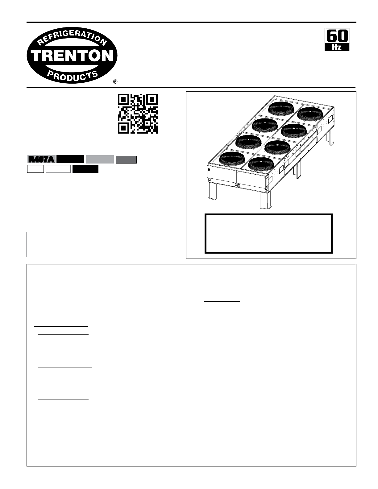
One to Fourteen Fan Motors
TCL-LINE
AIR COOLED
CONDENSERS
R407A
R22
R407C
R410A
R404A
R134a
R507
Electrical Power:
208-230/3/60, 460/3/60, 575/3/60
Bulletin T50-TCL-PDI-4
1089597
?
Questions about this product?
Email: acc-fc@t-rp.com
Call: 1-844-893-3222 x526
Page
CONTENTS
Nomenclature............................................. 2
Features & Options.................................... 2
Standard Motors
850 RPM Motors:
Capacity Data......................................... 3 - 4
Electrical Data........................................ 5
General Specications........................... 6 - 7
1140 RPM Motors:
Capacity Data......................................... 8 - 9
Electrical Data........................................ 10
General Specications........................... 11 - 12
550 RPM Motors:
Capacity Data......................................... 13 - 14
Electrical Data........................................ 15
General Specications........................... 16 - 17
Wiring Diagrams......................................... 18 - 20
Comparative Sound Data................................. 21
?
INCLUDES RATINGS FOR
EC Motors Page
About EC Motors................................ 22
Power Consumption Comparison....... 22
Capacity Data...................................... 23 - 24
Electrical Data..................................... 25
General Specications........................ 26 - 27
EC Motor Application.......................... 28
Wiring Diagrams................................. 29 -30
Dimensional Data (All Models)............ 31 - 34
Condenser Theory ............................... 35
Glossary of Terms............................... 35 - 36
Condenser Selection........................... 36 - 40
Low Ambient Operation....................... 42 - 47
Installation........................................... 48 - 51
Service Parts...................................... 52
Warranty.............................................. 55
Project Information.............................. 55
“As Built” Service Parts List................. BACK
Page 2

Brand Name:
05/08/15
T50-TCL-PDI-4
- 2 -
T = Trenton
Product name
CL = Large Sized Condenser
Nominal Tons (R404A, 25°F TD, 60Hz)
Voltage
T3 = 208-230/3/60
T4 = 460/3/60
T5 = 575/3/60
T7 = 200-220/3/50
T9 = 380-400/3/50
Design version
STANDARD FEATURES INCLUDE
NOMENCLATURE
T CL 230 - T3 A - A 2 7 V - XXXX
Optional Sufx
Does Not Affect Design
Application
V = Vertical Air Discharge
H = Horizontal Air Discharge
Fans Deep
Fans Wide
1 = Inline; 2 = Double Wide
Motor
A = 850 RPM, 1 HP Motor
B = 550 RPM, 1/2 HP Motor
C = 1140 RPM, 2 HP Motor
E = EC Motor - Packaged Assembly
M = EC Motor - Motor Only
(Conventional Shafted Style Motor)
• Compatable with Low GWP Refrigerants
• Internally Enhanced Tube
• Narrow width condenser design to suit shipment in
containers.
• THERMOSPANTM coil design feature eliminates tube
failure on tube sheets.
• Enhanced Copper Tube, (3/8 O.D. on 1-6 Fan, 1/2 O.D.
on 8-14 Fan) Aluminum Fin Condenser Coils
• Standard 850 RPM quiet low speed fan motors
with male electrical plug, moisture slinger, and rainshield
for complete weather protection.
• Swept wing fan for quiet operation and optimal efciency
• Rugged heavy-gauge galvanized steel rail
motor mounts / support.
OPTIONAL FEATURES
• Multiple refrigeration circuits
• Fan Cycling – Ambient thermostat / fan row
with contactors
• All fan sections individually bafed with full
height partitions, and clean-out panels.
• Complete selection of electrical fan cycling and
speed control options.
• Heavy-gauge galvanized steel cabinet
construction assembled with zinc plated huck
bolts supported on heavy-duty legs.
• 2-Fan wide units have two equal circuits
• Terminal block
• Single entering electrical service
• Control circuit voltage – 230 V
• Control circuit transformer where applicable
• Variable Speed EC Motors which provide optimum
efciency and sound levels (see pg. 22-34 for details)
• Adjustable ooded head pressure control
• Fan Cycling – Pressure control / fan row
with contactors
• Variable speed motor with controller
for header fan motors
• Individual fan motor fusing
• Individual ambient thermostat or pressure control
• Non-fused disconnect
• Horizontal air discharge conguration
• Extended leg kits (36” or 48”) with cross bracing for
extra rigidity
• Optional 550 ultra low and 1140 RPM high
speed motors available.
• Optional n materials
• Optional coil coating
• Voltages available for 60Hz or 50Hz
Page 3
TCL
05/08/15
T50-TCL-PDI-4
- 3 -
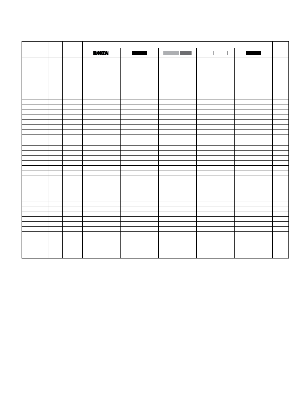
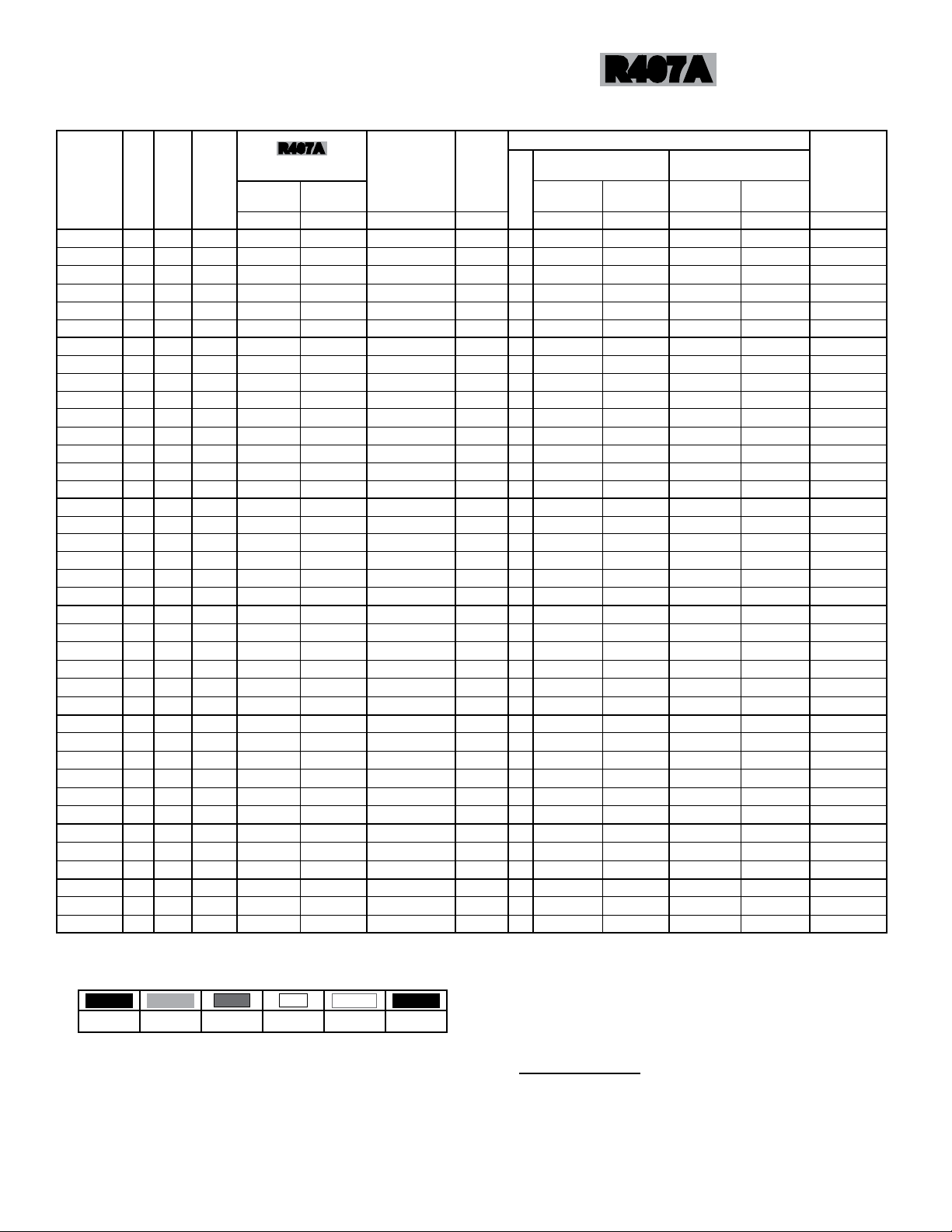
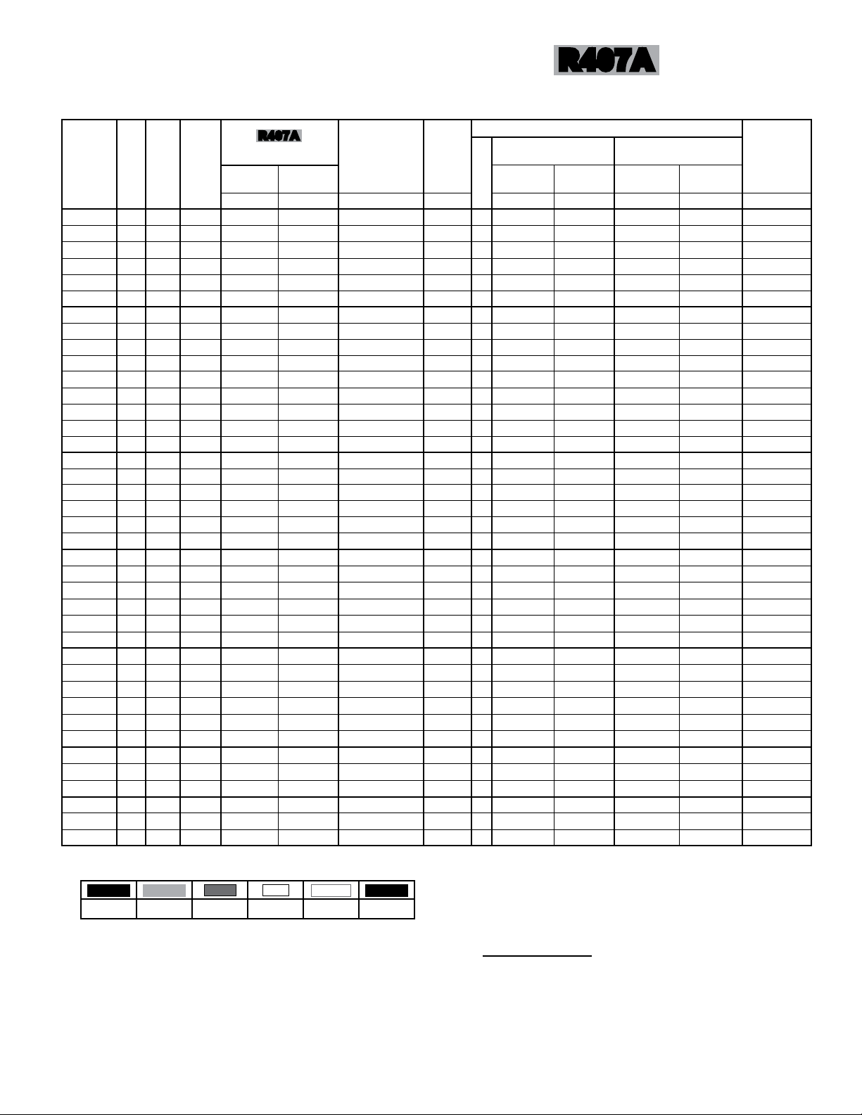
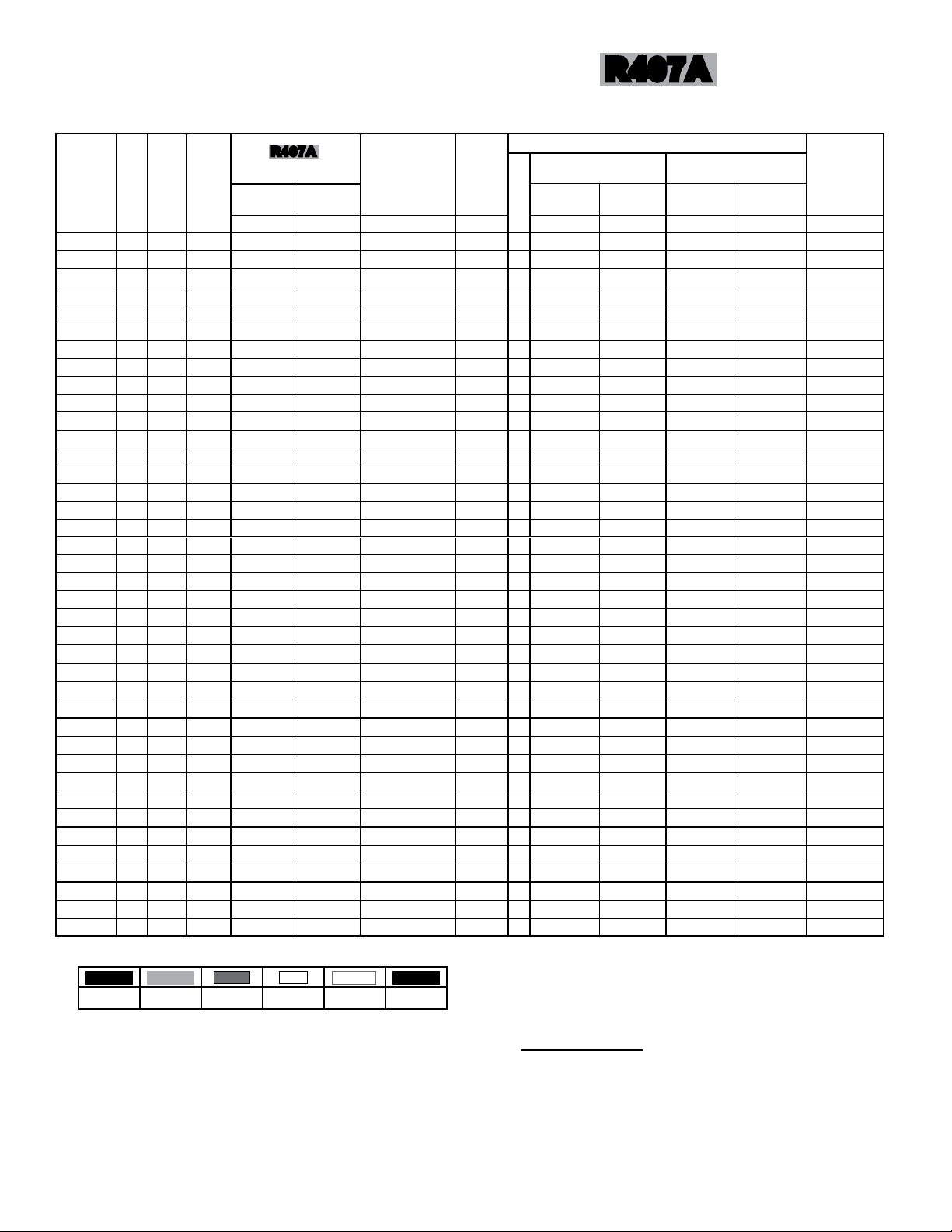
CAPACITY DATA -
SINGLE ROW MODELS
850 RPM
60Hz
MODEL
NO.
TCL 012 8 1 x 1 5.40 (1.58) 5.58 (1.63) 5.87 (1.72) 5.99 (1.75) 5.69 (1.67) 7
TCL 013 10 1 x 1 5.90 (1.73) 6.09 (1.79) 6.41 (1.88) 6.54 (1.92) 6.22 (1.82) 7
TCL 014 12 1 x 1 6.27 (1.84) 6.48 (1.90) 6.82 (2.00) 6.96 (2.04) 6.62 (1.94) 7
TCL 015 8 1 x 1 6.36 (1.87) 6.56 (1.93) 6.91 (2.03) 7.05 (2.07) 6.70 (1.97) 8
TCL 016 10 1 x 1 6.86 (2.01) 7.09 (2.08) 7.46 (2.19) 7.61 (2.23) 7.24 (2.12) 8
TCL 017 12 1 x 1 7.15 (2.10) 7.38 (2.17) 7.77 (2.28) 7.93 (2.33) 7.54 (2.21) 8
TCL 019 8 1 x 2 8.29 (2.43) 8.56 (2.51) 9.01 (2.64) 9.19 (2.69) 8.74 (2.56) 9
TCL 021 10 1 x 2 9.30 (2.72) 9.60 (2.81) 10.11 (2.96) 10.31 (3.02) 9.81 (2.87) 9
TCL 023 12 1 x 2 10.11 (2.96) 10.44 (3.06) 10.99 (3.22) 11.21 (3.28) 10.66 (3.12) 9
TCL 024 8 1 x 2 10.79 (3.16) 11.14 (3.27) 11.73 (3.44) 11.96 (3.51) 11.38 (3.34) 14
TCL 027 10 1 x 2 11.79 (3.46) 12.18 (3.57) 12.82 (3.76) 13.08 (3.84) 12.44 (3.65) 14
TCL 028 12 1 x 2 12.55 (3.68) 12.96 (3.80) 13.64 (4.00) 13.91 (4.08) 13.23 (3.88) 14
TCL 029 8 1 x 2 12.53 (3.67) 12.94 (3.79) 13.62 (3.99) 13.89 (4.07) 13.21 (3.87) 18
TCL 031 10 1 x 2 13.52 (3.97) 13.97 (4.09) 14.7 (4.31) 14.99 (4.40) 14.26 (4.18) 18
TCL 032 12 1 x 2 14.09 (4.13) 14.54 (4.27) 15.31 (4.49) 15.62 (4.58) 14.85 (4.36) 18
TCL 037 8 1 x 3 16.19 (4.75) 16.72 (4.90) 17.6 (5.16) 17.95 (5.26) 17.07 (5.01) 21
TCL 040 10 1 x 3 17.69 (5.19) 18.27 (5.36) 19.23 (5.64) 19.61 (5.75) 18.65 (5.47) 21
TCL 042 12 1 x 3 18.82 (5.52) 19.44 (5.70) 20.46 (6.00) 20.87 (6.12) 19.85 (5.82) 21
TCL 043 8 1 x 3 19.14 (5.61) 19.76 (5.80) 20.8 (6.10) 21.22 (6.22) 20.18 (5.92) 28
TCL 047 10 1 x 3 20.64 (6.05) 21.32 (6.25) 22.44 (6.58) 22.89 (6.71) 21.77 (6.38) 28
TCL 049 12 1 x 3 21.51 (6.30) 22.21 (6.51) 23.38 (6.85) 23.85 (6.99) 22.68 (6.64) 28
TCL 051 8 1 x 4 22.59 (6.61) 23.32 (6.83) 24.55 (7.19) 25.04 (7.33) 23.81 (6.97) 21
TCL 056 10 1 x 4 24.68 (7.23) 25.49 (7.47) 26.83 (7.86) 27.37 (8.02) 26.03 (7.62) 21
TCL 059 12 1 x 4 26.26 (7.70) 27.11 (7.95) 28.54 (8.37) 29.11 (8.54) 27.68 (8.12) 21
TCL 060 8 1 x 4 26.36 (7.73) 27.22 (7.98) 28.65 (8.40) 29.22 (8.57) 27.79 (8.15) 28
TCL 064 10 1 x 4 28.44 (8.34) 29.36 (8.61) 30.91 (9.06) 31.53 (9.24) 29.98 (8.79) 28
TCL 067 12 1 x 4 29.61 (8.68) 30.58 (8.97) 32.19 (9.44) 32.83 (9.63) 31.22 (9.16) 28
TCL 063 8 1 x 5 27.78 (8.14) 28.69 (8.41) 30.2 (8.85) 30.80 (9.03) 29.29 (8.58) 21
TCL 069 10 1 x 5 30.37 (8.91) 31.36 (9.20) 33.01 (9.68) 33.67 (9.87) 32.02 (9.39) 21
TCL 073 12 1 x 5 32.31 (9.47) 33.36 (9.78) 35.12 (10.29) 35.82 (10.50) 34.07 (9.98) 21
TCL 075 8 1 x 5 33.14 (9.72) 34.22 (10.03) 36.02 (10.56) 36.74 (10.77) 34.94 (10.24) 28
TCL 081
TCL 084 12 1 x 5 37.23 (10.91) 38.45 (11.27) 40.47 (11.86) 41.28 (12.10) 39.26 (11.50) 28
TCL 089 8 1 x 6 39.37 (11.54) 40.65 (11.91) 42.79 (12.54) 43.65 (12.79) 41.51 (12.16) 28
TCL 096 10 1 x 6 42.47 (12.45) 43.85 (12.85) 46.16 (13.53) 47.08 (13.80) 44.78 (13.12) 28
TCL 100 12 1 x 6 44.23 (12.96) 45.68 (13.39) 48.08 (14.09) 49.04 (14.37) 46.64 (13.67) 28
TCL 102 8 1 x 7 45.25 (13.26) 46.72 (13.69) 49.18 (14.41) 50.16 (14.70) 47.70 (13.98) 56
TCL 111 10 1 x 7 48.80 (14.31) 50.39 (14.77) 53.04 (15.55) 54.10 (15.86) 51.45 (15.08) 56
TCL 115 12 1 x 7 50.83 (14.89) 52.49 (15.38) 55.25 (16.19) 56.36 (16.51) 53.59 (15.70) 56
FPI
FAN
CONFIG.
10 1 x 5 35.74 (10.48) 36.91 (10.82) 38.85 (11.39) 39.63 (11.62) 37.68 (11.05) 28
R407A
TOTAL HEAT OF REJECTION - MBH (KW) PER 1 °F (0.56 °C) TD MAX.
R407C R404A
R507
R22
R410A
R134a
NO. OF
FEEDS
NOTES:
- Above capacity data based on 0oF subcooling and at sea level.
- For High Altitude applications apply the following correction factors: 0.94 for 2000 feet, 0.88 for 4000 feet and 0.81 for 6000 feet.
- Capacities at other TD within a range of 10 to 30 °F (-12.2 to -1°C) are directly proportional to TD, or use formula: Capacity = Rated capacity ÷ 10 x TD.
- For 50 HZ capacity multiply by 0.92.
- Capacities for R407A and R407C are based on mean temperature. Mean temperature is the average temperature between the saturated condensing
temperatures at the inlet and outlet of the condenser. For dew point ratings, consult factory.
Page 4
TCL
05/08/15
T50-TCL-PDI-4
- 4 -
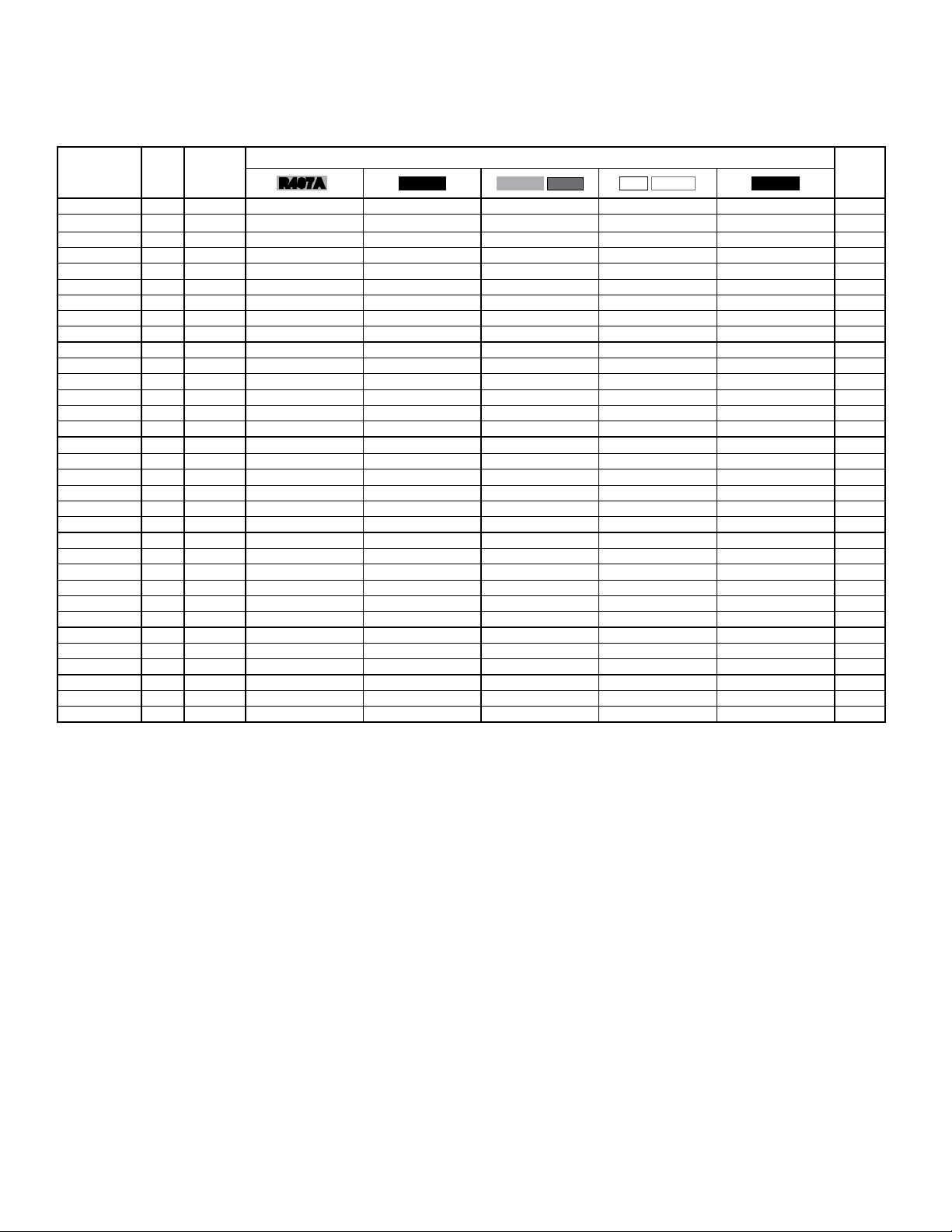
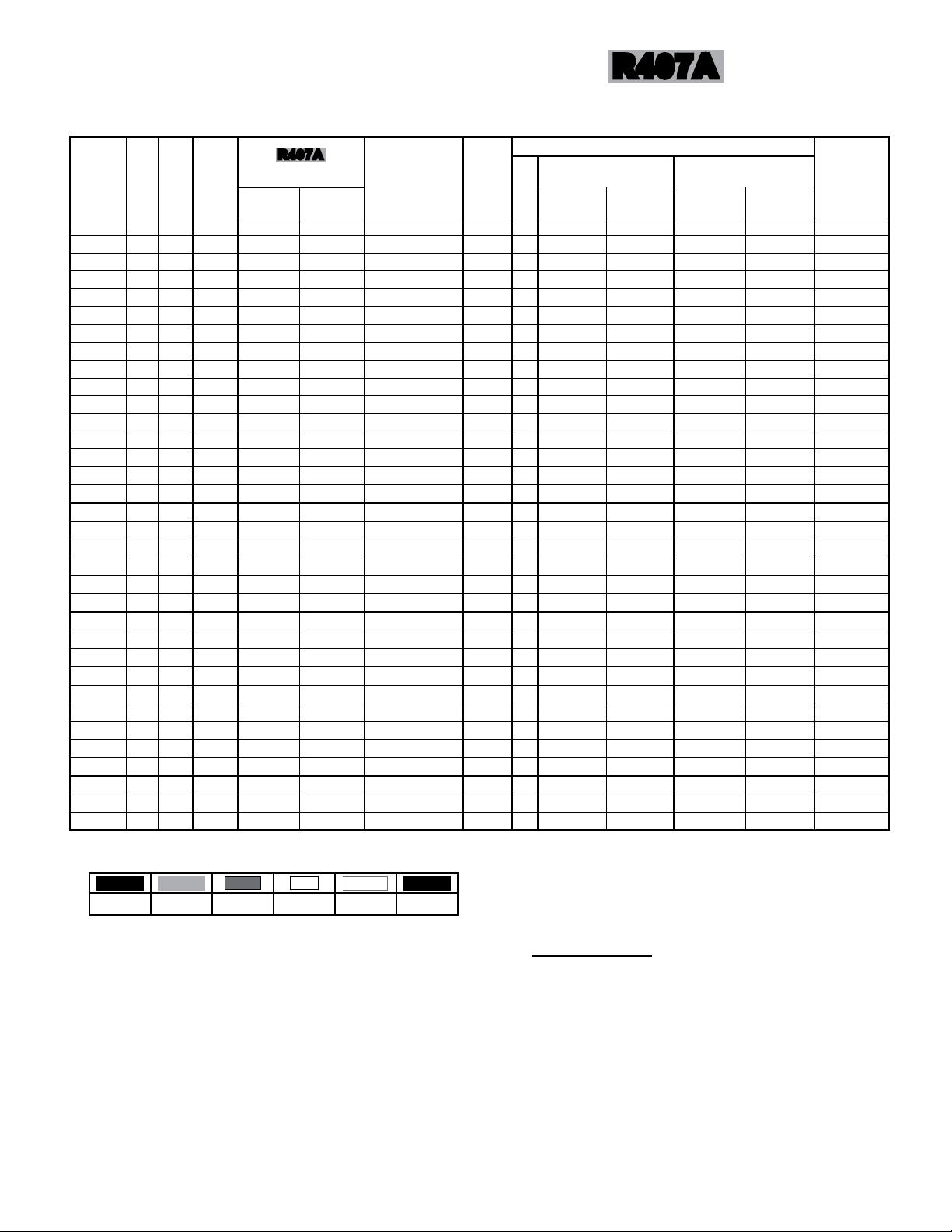
CAPACITY DATA -
DOUBLE ROW MODELS
850 RPM
60Hz
MODEL
NO.
TCL 038 8 2 x 2 16.58 (4.86) 17.12 (5.02) 18.02 (5.28) 18.38 (5.39) 17.48 (5.12) 18
TCL 041 10 2 x 2 18.60 (5.45) 19.21 (5.63) 20.22 (5.93) 20.62 (6.04) 19.61 (5.75) 18
TCL 046 12 2 x 2 20.21 (5.92) 20.87 (6.12) 21.97 (6.44) 22.41 (6.57) 21.31 (6.25) 18
TCL 048 8 2 x 2 21.58 (6.33) 22.29 (6.53) 23.46 (6.88) 23.93 (7.01) 22.76 (6.67) 28
TCL 054 10 2 x 2 23.59 (6.91) 24.36 (7.14) 25.64 (7.52) 26.15 (7.67) 24.87 (7.29) 28
TCL 057 12 2 x 2 25.10 (7.36) 25.92 (7.60) 27.28 (8.00) 27.83 (8.15) 26.46 (7.76) 28
TCL 058 8 2 x 2 25.41 (7.45) 26.24 (7.69) 27.62 (8.09) 28.17 (8.26) 26.79 (7.85) 37
TCL 062 10 2 x 2 27.41 (8.03) 28.30 (8.29) 29.79 (8.73) 30.39 (8.91) 28.90 (8.47) 37
TCL 065 12 2 x 2 28.55 (8.37) 29.48 (8.64) 31.03 (9.09) 31.65 (9.28) 30.10 (8.82) 37
TCL 072 8 2 x 3 32.37 (9.49) 33.43 (9.79) 35.19 (10.31) 35.89 (10.52) 34.13 (10.00) 42
TCL 080 10 2 x 3 35.39 (10.37) 36.55 (10.71) 38.47 (11.27) 39.24 (11.50) 37.32 (10.93) 42
TCL 085 12 2 x 3 37.65 (11.03) 38.87 (11.39) 40.92 (11.99) 41.74 (12.23) 39.69 (11.63) 42
TCL 087 8 2 x 3 38.28 (11.21) 39.53 (11.58) 41.61 (12.19) 42.44 (12.43) 40.36 (11.82) 56
TCL 094 10 2 x 3 41.29 (12.10) 42.64 (12.49) 44.88 (13.15) 45.78 (13.41) 43.53 (12.76) 56
TCL 097 12 2 x 3 43.01 (12.60) 44.41 (13.02) 46.75 (13.70) 47.69 (13.97) 45.35 (13.29) 56
TCL 103 8 2 x 4 45.16 (13.24) 46.64 (13.67) 49.09 (14.39) 50.07 (14.68) 47.62 (13.96) 42
TCL 112 10 2 x 4 49.37 (14.47) 50.98 (14.94) 53.66 (15.73) 54.73 (16.04) 52.05 (15.26) 42
TCL 119 12 2 x 4 52.51 (15.39) 54.23 (15.89) 57.08 (16.73) 58.22 (17.06) 55.37 (16.23) 42
TCL 120 8 2 x 4 52.72 (15.45) 54.44 (15.95) 57.3 (16.79) 58.45 (17.13) 55.58 (16.29) 56
TCL 129 10 2 x 4 56.87 (16.67) 58.72 (17.21) 61.81 (18.12) 63.05 (18.48) 59.96 (17.58) 56
TCL 134 12 2 x 4 59.24 (17.36) 61.17 (17.93) 64.39 (18.87) 65.68 (19.25) 62.46 (18.30) 56
TCL 126 8 2 x 5 55.57 (16.28) 57.38 (16.82) 60.4 (17.70) 61.61 (18.05) 58.59 (17.17) 42
TCL 138 10 2 x 5 60.74 (17.80) 62.72 (18.38) 66.02 (19.35) 67.34 (19.74) 64.04 (18.77) 42
TCL 146 12 2 x 5 64.62 (18.93) 66.73 (19.55) 70.24 (20.58) 71.64 (20.99) 68.13 (19.96) 42
TCL 150 8 2 x 5 66.28 (19.42) 68.44 (20.05) 72.04 (21.11) 73.48 (21.53) 69.88 (20.48) 56
TCL 162 10 2 x 5 71.49 (20.95) 73.82 (21.63) 77.71 (22.77) 79.26 (23.23) 75.38 (22.09) 56
TCL 168 12 2 x 5 74.46 (21.82) 76.89 (22.53) 80.94 (23.72) 82.56 (24.19) 78.51 (23.01) 56
TCL 178 8 2 x 6 78.73 (23.07) 81.30 (23.83) 85.58 (25.08) 87.29 (25.58) 83.01 (24.33) 56
TCL 192 10 2 x 6 84.93 (24.89) 87.69 (25.70) 92.31 (27.05) 94.16 (27.59) 89.54 (26.24) 56
TCL 200 12 2 x 6 88.47 (25.93) 91.35 (26.77) 96.16 (28.18) 98.08 (28.74) 93.28 (27.33) 56
TCL 205 8 2 x 7 90.48 (26.51) 93.43 (27.38) 98.35 (28.82) 100.32 (29.40) 95.40 (27.96) 112
221 10 2 x 7 97.61 (28.60) 100.80 (29.54) 106.1 (31.09) 108.22 (31.71) 102.92 (30.16) 112
TCL
TCL 230 12 2 x 7 101.66 (29.80) 104.98 (30.77) 110.5 (32.39) 112.71 (33.04) 107.19 (31.42) 112
FPI
FAN
CONFIG.
R407A
TOTAL HEAT OF REJECTION - MBH (KW) PER 1 °F (0.56 °C) TD MAX.
R407C R404A
R507
R22
R410A
R134a
NO. OF
FEEDS
NOTES:
- Above capacity data based on 0oF subcooling and at sea level.
- For High Altitude applications apply the following correction factors: 0.94 for 2000 feet, 0.88 for 4000 feet and 0.81 for 6000 feet.
- Capacities at other TD within a range of 10 to 30 °F (-12.2 to -1°C) are directly proportional to TD, or use formula: Capacity = Rated capacity ÷ 10 x TD.
- For 50 HZ capacity multiply by 0.92.
- Capacities for R407A and R407C are based on mean temperature. Mean temperature is the average temperature between the saturated condensing
temperatures at the inlet and outlet of the condenser. For dew point ratings, consult factory.
Page 5
TCL
05/08/15
T50-TCL-PDI-4
- 5 -
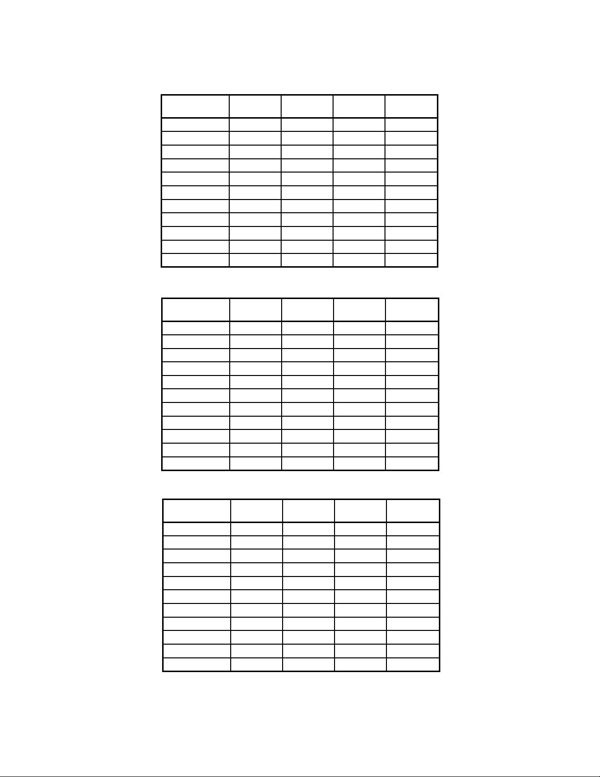
ELECTRICAL DATA
208-230/3/60
NO. OF FAN
MOTORS
1 4.9 6.1 15 900
2 9.8 11 15 1800
3 14.7 15.9 20 2700
4 19.6 20.8 25 3600
5 24.5 31 35 4500
6 29.4 36 40 5400
7 34.3 41 45 6300
8 39.2 46 50 7200
10 49.0 61 70 9000
12 58.8 71 80 10800
14 68.6 81 90 12600
NO. OF FAN
MOTORS
1 2.2 2.8 15 900
2 4.4 5 15 1800
3 6.6 7.2 15 2700
4 8.8 9.4 15 3600
5 11 11.6 15 4500
6 13.2 16 20 5400
7 15.4 16 20 6300
8 17.6 21 25 7200
10 22 26 30 9000
12 26.4 31 35 10800
14 30.8 36 40 12600
TOTAL FLA MCA MOP WATTS
460/3/60
TOTAL FLA MCA MOP WATTS
850 RPM
60Hz
575/3/60
NO. OF FAN
MOTORS
1 2.1 2.6 15.0 1040
2 4.2 4.7 15.0 2080
3 6.3 6.8 15.0 3120
4 8.4 8.9 15.0 4160
5 10.5 11.0 15.0 5200
6 12.6 16.0 20.0 6240
7 14.7 16.0 20.0 7280
8 16.8 21.0 25.0 8320
10 21.0 26.0 30.0 10400
12 25.2 31.0 35.0 12480
14 29.4 36.0 40.0 14560
M.C.A. = Minimum Circuit Ampacity M.O.P. = Maximum Overcurrent Protection
TOTAL FLA MCA MOP WATTS
Page 6
TCL
05/08/15
T50-TCL-PDI-4
- 6 -
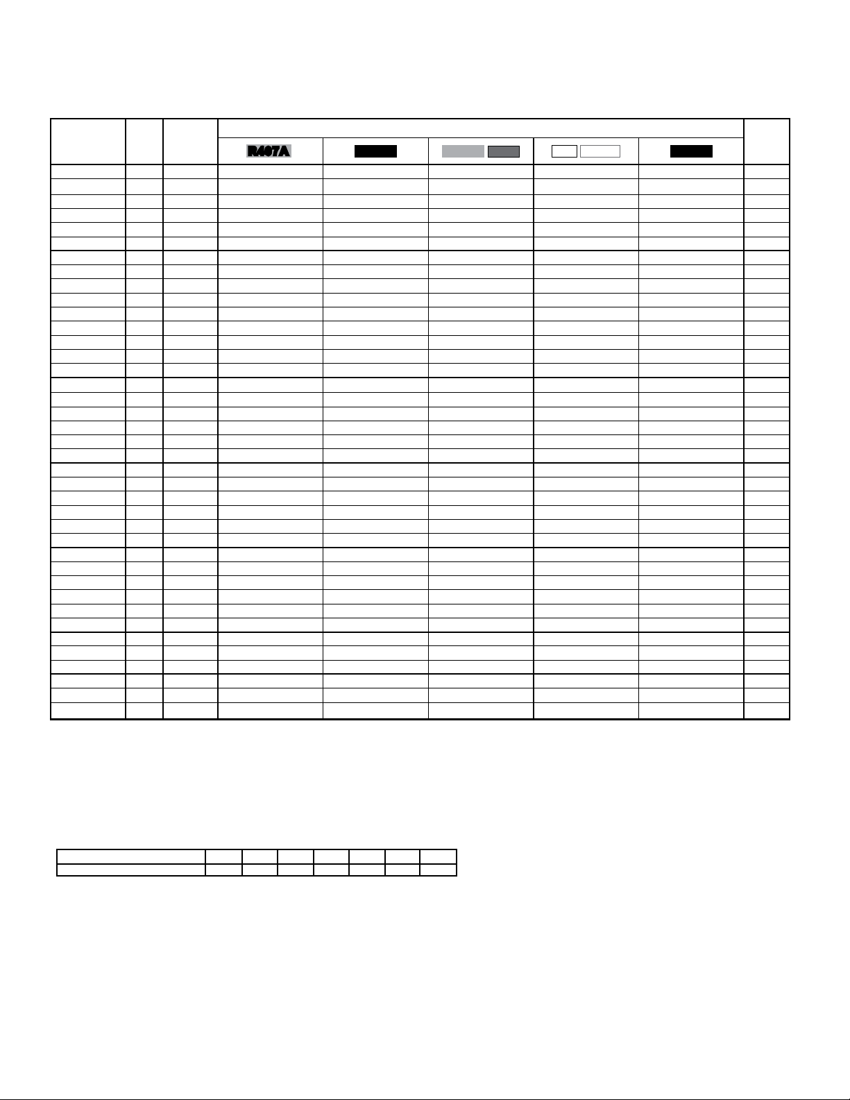
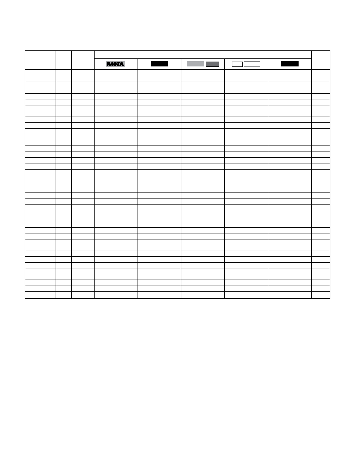
GENERAL SPECIFICATIONS -
SINGLE ROW MODELS
R407A
850 RPM
60Hz
MODEL
NO.
FPI
MAX.
NO. OF
FEEDS
FAN CONFIG.
TCL 012 8 1 x 1 7
TCL 013 10 1 x 1 7
TCL 014 12 1 x 1 7
TCL 015 8 1 x 1 8
TCL 016 10 1 x 1 8
TCL 017 12 1 x 1 8
TCL 019 8 1 x 2 9
TCL 021 10 1 x 2 9
TCL 023 12 1 x 2 9
TCL 024 8 1 x 2 14
TCL 027 10 1 x 2 14
TCL 028 12 1 x 2 14
TCL 029 8 1 x 2 18
TCL 031 10 1 x 2 18
TCL 032 12 1 x 2 18
TCL 037 8 1 x 3 21
TCL 040 10 1 x 3 21
TCL 042 12 1 x 3 21
TCL 043 8 1 x 3 28
TCL 047 10 1 x 3 28
TCL 049 12 1 x 3 28
TCL 051 8 1 x 4 21
TCL 056 10 1 x 4 21
TCL 059 12 1 x 4 21
TCL 060 8 1 x 4 28
TCL 064 10 1 x 4 28
TCL 067 12 1 x 4 28
TCL 063 8 1 x 5 21
TCL 069 10 1 x 5 21
TCL 073 12 1 x 5 21
TCL 075 8 1 x 5 28
TCL 081 10 1 x 5 28
TCL 084 12 1 x 5 28
TCL 089 8 1 x 6 28
TCL 096 10 1 x 6 28
TCL 100 12 1 x 6 28
TCL 102 8 1 x 7 56
TCL 111 10 1 x 7 56
TCL 115 12 1 x 7 56
R407A
REFRIG. CHARGE
(2)
90% FULL
NORMAL
LBS (kg) LBS (kg) CFM (m
6 (2.5) 25 (12) 9000
6 (2.5) 25 (12) 8700
6 (2.5) 25 (12) 8400
7 (3.1) 32 (14) 8500
7 (3.1) 32 (14) 8200
7 (3.1) 32 (14) 7900
8 (3.6) 36 (17) 19100
8 (3.6) 36 (17) 18400
8 (3.6) 36 (17) 17800
11 (5.1) 50 (23) 18000
11 (5.1) 50 (23) 17400
11 (5.1) 50 (23) 16800
13 (6.1) 63 (29) 17000
13 (6.1) 63 (29) 16400
13 (6.1) 63 (29) 15900
15 (6.8) 73 (33) 27000
15 (6.8) 73 (33) 26100
15 (6.8) 73 (33) 25200
21 (9.4) 96 (43) 25500
21 (9.4) 96 (43) 24600
21 (9.4) 96 (43) 23800
32 (14) 162 (74) 34900
32 (14) 162 (74) 33800
32 (14) 162 (74) 32600
41 (19) 210 (96) 33000
41 (19) 210 (96) 31900
41 (19) 210 (96) 30800
42 (19) 206 (94) 43700
42 (19) 206 (94) 42200
42 (19) 206 (94) 40800
53 (24) 266 (121) 41200
53 (24) 266 (121) 39800
53 (24) 266 (121) 38500
61 (28) 314 (143) 49400
61 (28) 314 (143) 47800
61 (28) 314 (143) 46200
69 (31) 362 (165) 57700
69 (31) 362 (165) 55800
69 (31) 362 (165) 53900
(1)
(3)
AIR
FLOW
RATES
(15290)
(14780)
(14270)
(14440)
(13930)
(13420)
(32450)
(31260)
(30240)
(30580)
(29560)
(28540)
(28880)
(27860)
(27010)
(45870)
(44340)
(42810)
(43320)
(41800)
(40440)
(59300)
(57430)
(55390)
(56070)
(54200)
(52330)
(74250)
(71700)
(69320)
(70000)
(67620)
(65410)
(83930)
(81210)
(78490)
(98030)
(94800)
(91580)
SOUND
LEVEL
(5)
3
/h) dBA IN.
QUANTITY
53 1
53 1
53 1
53 1
53 1
53 1
55 1
55 1
55 1
55 1
55 1
55 1
55 1
55 1
55 1
56 1
56 1
56 1
56 1
56 1
56 1
57 1
57 1
57 1
57 1
57 1
57 1
58 1
58 1
58 1
58 1
58 1
58 1
59 1
59 1
59 1
59 1
59 1
59 1
PIPING CONNECTIONS
16°F to 30°F
DESIGN TD
10°F to 15°F
DESIGN TD
INLET OUTLET INLET OUTLET
1 5/8
1 5/8
1 5/8
1 5/8
1 5/8
1 5/8
2 1/8
2 1/8
2 1/8
2 1/8
2 1/8
2 1/8
2 1/8
2 1/8
2 1/8
2 5/8
2 5/8
2 5/8
2 5/8
2 5/8
2 5/8
2 5/8
2 5/8
2 5/8
2 5/8
2 5/8
2 5/8
2 5/8
2 5/8
2 5/8
2 5/8
2 5/8
2 5/8
3 1/8
3 1/8
3 1/8
3 1/8
3 1/8
3 1/8
(mm)
(41)
(41)
(41)
(41)
(41)
(41)
(54)
(54)
(54)
(54)
(54)
(54)
(54)
(54)
(54)
(67)
(67)
(67)
(67)
(67)
(67)
(67)
(67)
(67)
(67)
(67)
(67)
(67)
(67)
(67)
(67)
(67)
(67)
(79)
(79)
(79)
(79)
(79)
(79)
IN.
1 1/8
1 1/8
1 1/8
1 1/8
1 1/8
1 1/8
1 3/8
1 3/8
1 3/8
1 5/8
1 5/8
1 5/8
1 5/8
1 5/8
1 5/8
1 5/8
1 5/8
1 5/8
1 5/8
1 5/8
1 5/8
2 1/8
2 1/8
2 1/8
2 1/8
2 1/8
2 1/8
2 1/8
2 1/8
2 1/8
2 5/8
2 5/8
2 5/8
2 5/8
2 5/8
2 5/8
2 5/8
2 5/8
2 5/8
(mm)
(29)
(29)
(29)
(29)
(29)
(29)
(35)
(35)
(35)
(41)
(41)
(41)
(41)
(41)
(41)
(41)
(41)
(41)
(41)
(41)
(41)
(54)
(54)
(54)
(54)
(54)
(54)
(54)
(54)
(54)
(67)
(67)
(67)
(67)
(67)
(67)
(67)
(67)
(67)
IN.
1 3/8
1 3/8
1 3/8
1 3/8
1 3/8
1 3/8
1 3/8
1 3/8
1 3/8
1 3/8
1 5/8
1 5/8
1 5/8
1 5/8
1 5/8
2 1/8
2 1/8
2 1/8
2 1/8
2 1/8
2 1/8
2 1/8
2 1/8
2 1/8
2 1/8
2 1/8
2 1/8
2 1/8
2 1/8
2 1/8
2 1/8
2 1/8
2 1/8
2 5/8
2 5/8
2 5/8
2 5/8
2 5/8
2 5/8
(mm)
(35)
(35)
(35)
(35)
(35)
(35)
(35)
(35)
(35)
(35)
(41)
(41)
(41)
(41)
(41)
(54)
(54)
(54)
(54)
(54)
(54)
(54)
(54)
(54)
(54)
(54)
(54)
(54)
(54)
(54)
(54)
(54)
(54)
(67)
(67)
(67)
(67)
(67)
(67)
IN.
7/8
7/8
7/8
7/8
7/8
7/8
1 1/8
1 1/8
1 1/8
1 1/8
1 1/8
1 1/8
1 1/8
1 1/8
1 1/8
1 3/8
1 3/8
1 3/8
1 3/8
1 3/8
1 3/8
1 3/8
1 3/8
1 3/8
1 5/8
1 5/8
1 5/8
1 5/8
1 5/8
1 5/8
1 5/8
1 5/8
1 5/8
2 1/8
2 1/8
2 1/8
2 1/8
2 1/8
2 1/8
(mm)
(22)
(22)
(22)
(22)
(22)
(22)
(29)
(29)
(29)
(29)
(29)
(29)
(29)
(29)
(29)
(35)
(35)
(35)
(35)
(35)
(35)
(35)
(35)
(35)
(41)
(41)
(41)
(41)
(41)
(41)
(41)
(41)
(41)
(54)
(54)
(54)
(54)
(54)
(54)
APPROX.
SHIPPING
WEIGHT
LBS (kg)
(161)
355
(164)
360
(168)
370
(173)
380
(177)
390
(182)
400
(302)
665
(305)
670
(309)
680
(323)
710
(327)
720
(336)
740
(350)
770
(355)
780
(364)
800
(477)
1050
(489)
1075
(500)
1100
(523)
1150
(534)
1175
(545)
1200
(648)
1425
(659)
1450
(670)
1475
(693)
1525
(705)
1550
(727)
1600
(784)
1725
(818)
1800
(841)
1850
(875)
1925
(886)
1950
(909)
2000
(1034)
2275
(1045)
2300
(1068)
2350
(1216)
2675
(1227)
2700
(1250)
2750
(1) Refrigerant charge conversion factors:
(2) Normal charge is the refrigerant charge for warm ambient or summer operation.
(3) 90% full is the liquid refrigerant weight at 90% of internal volume and is for reference only.
(4) For 50 Hz fan data use 60 Hz CFM (m3/h) X 0.83
(5) Sound pressure level at 30 ft. (10 m) See page 21 for more data
R407C R404A
R507
R22
R410A
1.0 0.91 0.91 1.05 0.92 1.06
R134a
Page 7
TCL
05/08/15
T50-TCL-PDI-4
- 7 -
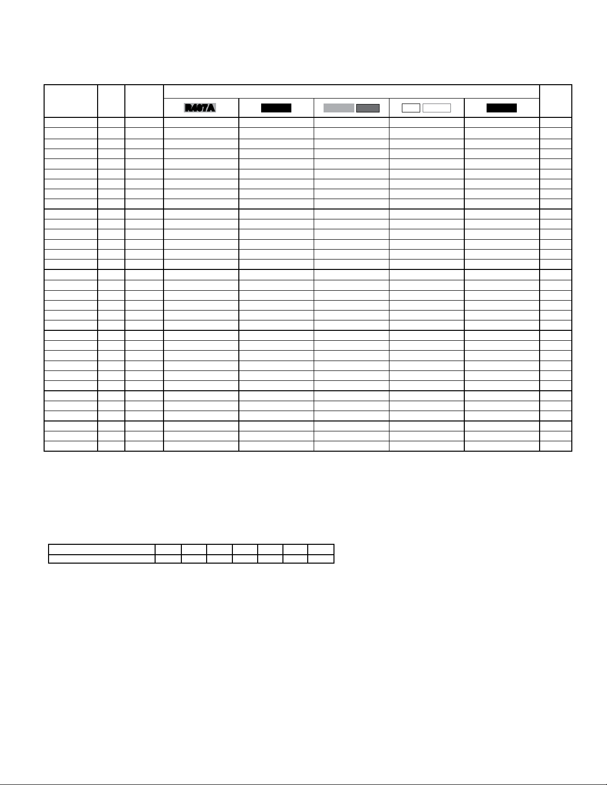
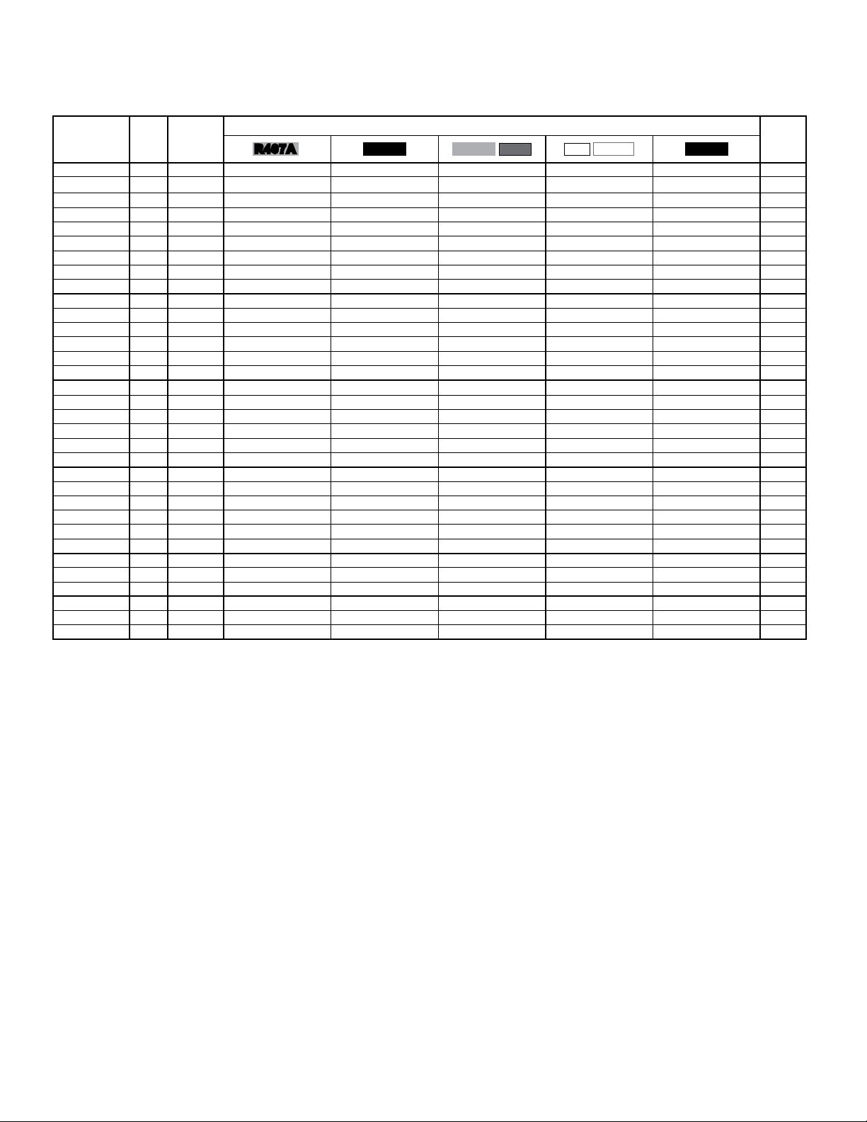
GENERAL SPECIFICATIONS -
DOUBLE ROW MODELS
R407A
850 RPM
60Hz
MODEL
NO.
FPI
MAX.
NO. OF
FEEDS
FAN CONFIG.
TCL 038 8 2 x 2 18
TCL 041 10 2 x 2 18
TCL 046 12 2 x 2 18
TCL 048 8 2 x 2 28
TCL 054 10 2 x 2 28
TCL 057 12 2 x 2 28
TCL 058 8 2 x 2 37
TCL 062 10 2 x 2 37
TCL 065 12 2 x 2 37
TCL 072 8 2 x 3 42
TCL 080 10 2 x 3 42
TCL 085 12 2 x 3 42
TCL 087 8 2 x 3 56
TCL 094 10 2 x 3 56
TCL 097 12 2 x 3 56
TCL 103 8 2 x 4 42
TCL 112 10 2 x 4 42
TCL 119 12 2 x 4 42
TCL 120 8 2 x 4 56
TCL 129 10 2 x 4 56
TCL 134 12 2 x 4 56
TCL 126 8 2 x 5 42
TCL 138 10 2 x 5 42
TCL 146 12 2 x 5 42
TCL 150 8 2 x 5 56
TCL 162 10 2 x 5 56
TCL 168 12 2 x 5 56
TCL 178 8 2 x 6 56
TCL 192 10 2 x 6 56
TCL 200 12 2 x 6 56
TCL 205 8 2 x 7 112
TCL 221 10 2 x 7 112
TCL 230 12 2 x 7 112
R407A
REFRIG. CHARGE
(2)
90% FULL
NORMAL
LBS (kg) LBS (kg) CFM (m
15 (7.7) 72 (33) 36000
15 (7.7) 72 (33) 34800
15 (7.7) 72 (33) 35600
22 (9.9) 100 (45) 33900
22 (9.9) 100 (45) 32800
22 (9.9) 100 (45) 33600
26 (12) 125 (57) 33900
26 (12) 125 (57) 32800
26 (12) 125 (57) 31700
30 (13) 146 (66) 54000
30 (13) 146 (66) 52200
30 (13) 146 (66) 50400
42 (19) 190 (87) 50900
42 (19) 190 (87) 49300
42 (19) 190 (87) 47600
64 (29) 323 (147) 69900
64 (29) 323 (147) 67600
64 (29) 323 (147) 65300
80 (36) 419 (190) 65900
80 (36) 419 (190) 63800
80 (36) 419 (190) 61600
84 (39) 411 (187) 87300
84 (39) 411 (187) 84500
84 (39) 411 (187) 81600
105 (47) 531 (242) 82400
105 (47) 531 (242) 79700
105 (47) 531 (242) 77000
121 (55) 628 (285) 98900
121 (55) 628 (285) 95600
121 (55) 628 (285) 92400
138 (63) 724 (329) 115300
138 (63) 724 (329) 111600
138 (63) 724 (329) 107800
(1)
(3)
AIR
FLOW
RATES
(61160)
(59130)
(60480)
(57600)
(55730)
(57090)
(57600)
(55730)
(53860)
(91750)
(88690)
(85630)
(86480)
(83760)
(80870)
(118760)
(114850)
(110940)
(111960)
(108400)
(104660)
(148320)
(143570)
(138640)
(140000)
(135410)
(130820)
(168030)
(162420)
(156990)
(195890)
(189610)
(183150)
SOUND
LEVEL
(5)
3
/h) dBA IN.
57 2
57 2
57 2
57 2
57 2
57 2
57 2
57 2
57 2
59 2
59 2
59 2
59 2
59 2
59 2
60 2
60 2
60 2
60 2
60 2
60 2
61 2
61 2
61 2
61 2
61 2
61 2
62 2
62 2
62 2
62 2
62 2
62 2
QUANTITY
2 1/8
2 1/8
2 1/8
2 1/8
2 1/8
2 1/8
2 1/8
2 1/8
2 1/8
2 5/8
2 5/8
2 5/8
2 5/8
2 5/8
2 5/8
2 5/8
2 5/8
2 5/8
2 5/8
2 5/8
2 5/8
2 5/8
2 5/8
2 5/8
2 5/8
2 5/8
2 5/8
3 1/8
3 1/8
3 1/8
3 1/8
3 1/8
3 1/8
PIPING CONNECTIONS
16°F to 30°F
DESIGN TD
10°F to 15°F
DESIGN TD
INLET OUTLET INLET OUTLET
(mm)
(54)
(54)
(54)
(54)
(54)
(54)
(54)
(54)
(54)
(67)
(67)
(67)
(67)
(67)
(67)
(67)
(67)
(67)
(67)
(67)
(67)
(67)
(67)
(67)
(67)
(67)
(67)
(79)
(79)
(79)
(79)
(79)
(79)
IN.
1 3/8
1 3/8
1 3/8
1 5/8
1 5/8
1 5/8
1 5/8
1 5/8
1 5/8
1 5/8
1 5/8
1 5/8
1 5/8
1 5/8
1 5/8
2 1/8
2 1/8
2 1/8
2 1/8
2 1/8
2 1/8
2 1/8
2 1/8
2 1/8
2 5/8
2 5/8
2 5/8
2 5/8
2 5/8
2 5/8
2 5/8
2 5/8
2 5/8
(mm)
(35)
(35)
(35)
(41)
(41)
(41)
(41)
(41)
(41)
(41)
(41)
(41)
(41)
(41)
(41)
(54)
(54)
(54)
(54)
(54)
(54)
(54)
(54)
(54)
(67)
(67)
(67)
(67)
(67)
(67)
(67)
(67)
(67)
IN.
1 3/8
1 3/8
1 3/8
1 3/8
1 5/8
1 5/8
1 5/8
1 5/8
1 5/8
2 1/8
2 1/8
2 1/8
2 1/8
2 1/8
2 1/8
2 1/8
2 1/8
2 1/8
2 1/8
2 1/8
2 1/8
2 1/8
2 1/8
2 1/8
2 1/8
2 1/8
2 1/8
2 5/8
2 5/8
2 5/8
2 5/8
2 5/8
2 5/8
(mm)
(67)
(67)
(67)
(67)
(67)
(67)
(67)
(67)
(67)
(67)
(67)
(67)
(67)
(67)
(67)
(67)
(67)
(67)
(67)
(67)
(67)
(67)
(67)
(67)
(67)
(67)
(67)
(67)
(67)
(67)
(67)
(67)
(67)
IN.
1 1/8
1 1/8
1 1/8
1 1/8
1 1/8
1 1/8
1 1/8
1 1/8
1 1/8
1 3/8
1 3/8
1 3/8
1 3/8
1 3/8
1 3/8
1 3/8
1 3/8
1 3/8
1 5/8
1 5/8
1 5/8
1 5/8
1 5/8
1 5/8
1 5/8
1 5/8
1 5/8
2 1/8
2 1/8
2 1/8
2 1/8
2 1/8
2 1/8
(mm)
(29)
(29)
(29)
(29)
(29)
(29)
(29)
(29)
(29)
(35)
(35)
(35)
(35)
(35)
(35)
(35)
(35)
(35)
(41)
(41)
(41)
(41)
(41)
(41)
(41)
(41)
(41)
(54)
(54)
(54)
(54)
(54)
(54)
APPROX.
SHIPPING
WEIGHT
LBS (kg)
(568)
1250
(580)
1275
(591)
1300
(602)
1325
(614)
1350
(636)
1400
(659)
1450
(670)
1475
(693)
1525
(920)
2025
(932)
2050
(955)
2100
(989)
2175
(1011)
2225
(1034)
2275
(1216)
2675
(1239)
2725
(1273)
2800
(1318)
2900
(1341)
2950
(1375)
3025
(1534)
3375
(1557)
3425
(1591)
3500
(1659)
3650
(1682)
3700
(1716)
3775
(1977)
4350
(2000)
4400
(2045)
4500
(2295)
5050
(2318)
5100
(2364)
5200
(1) Refrigerant charge conversion factors:
(2) Normal charge is the refrigerant charge for warm ambient or summer operation.
(3) 90% full is the liquid refrigerant weight at 90% of internal volume and is for reference only.
(4) For 50 Hz fan data use 60 Hz CFM (m3/h) X 0.83
(5) Sound pressure level at 30 ft. (10 m) See page 21 for more data
R407C R404A
R507
R22
R410A
1.0 0.91 0.91 1.05 0.92 1.06
R134a
Page 8
TCL
05/08/15
T50-TCL-PDI-4
- 8 -
CAPACITY DATA -
SINGLE ROW MODELS
1140 RPM
60Hz
MODEL
NO.
TCL 014 8 1 x 1 6.03 (1.76) 6.22 (1.82) 6.55 (1.92) 6.68 (1.96) 6.35 (1.86) 7
TCL 015 10 1 x 1 6.58 (1.93) 6.79 (1.99) 7.15 (2.10) 7.29 (2.14) 6.94 (2.03) 7
TCL 016 12 1 x 1 7.00 (2.05) 7.23 (2.12) 7.61 (2.23) 7.76 (2.27) 7.38 (2.16) 7
TCL 017 8 1 x 1 7.29 (2.14) 7.52 (2.21) 7.92 (2.32) 8.08 (2.37) 7.68 (2.25) 8
TCL 018 10 1 x 1 7.87 (2.30) 8.12 (2.38) 8.55 (2.51) 8.72 (2.56) 8.29 (2.43) 8
TCL 019 12 1 x 1 8.19 (2.40) 8.46 (2.48) 8.9 (2.61) 9.08 (2.66) 8.63 (2.53) 8
TCL 021 8 1 x 2 9.15 (2.68) 9.45 (2.77) 9.95 (2.92) 10.15 (2.98) 9.65 (2.83) 9
TCL 023 10 1 x 2 10.28 (3.01) 10.61 (3.11) 11.17 (3.27) 11.39 (3.34) 10.83 (3.17) 9
TCL 025 12 1 x 2 11.17 (3.27) 11.53 (3.38) 12.14 (3.56) 12.38 (3.63) 11.78 (3.45) 9
TCL 027 8 1 x 2 12.04 (3.53) 12.44 (3.64) 13.09 (3.84) 13.35 (3.91) 12.70 (3.72) 14
TCL 030 10 1 x 2 13.17 (3.86) 13.59 (3.98) 14.31 (4.19) 14.60 (4.28) 13.88 (4.07) 14
TCL 032 12 1 x 2 14.00 (4.10) 14.46 (4.24) 15.22 (4.46) 15.52 (4.55) 14.76 (4.33) 14
TCL 033 8 1 x 2 14.38 (4.21) 14.85 (4.35) 15.63 (4.58) 15.94 (4.67) 15.16 (4.44) 18
TCL 035 10 1 x 2 15.50 (4.54) 16.01 (4.69) 16.85 (4.94) 17.19 (5.04) 16.34 (4.79) 18
TCL 037 12 1 x 2 16.16 (4.73) 16.68 (4.89) 17.56 (5.15) 17.91 (5.25) 17.03 (4.99) 18
TCL 041 8 1 x 3 18.07 (5.29) 18.66 (5.47) 19.64 (5.76) 20.03 (5.87) 19.05 (5.58) 21
TCL 045 10 1 x 3 19.74 (5.79) 20.39 (5.98) 21.46 (6.29) 21.89 (6.42) 20.82 (6.10) 21
TCL 048 12 1 x 3 21.00 (6.16) 21.69 (6.36) 22.83 (6.69) 23.29 (6.82) 22.15 (6.49) 21
TCL 050 8 1 x 3 21.95 (6.43) 22.67 (6.64) 23.86 (6.99) 24.34 (7.13) 23.14 (6.78) 28
TCL 054 10 1 x 3 23.68 (6.94) 24.45 (7.17) 25.74 (7.54) 26.25 (7.69) 24.97 (7.32) 28
TCL 056 12 1 x 3 24.67 (7.23) 25.47 (7.46) 26.81 (7.86) 27.35 (8.01) 26.01 (7.62) 28
TCL 059 8 1 x 4 25.94 (7.60) 26.79 (7.85) 28.2 (8.26) 28.76 (8.43) 27.35 (8.02) 21
TCL 064 10 1 x 4 28.35 (8.31) 29.28 (8.58) 30.82 (9.03) 31.44 (9.21) 29.90 (8.76) 21
TCL 068 12 1 x 4 30.17 (8.84) 31.15 (9.13) 32.79 (9.61) 33.45 (9.80) 31.81 (9.32) 21
TCL 070 8 1 x 4 30.88 (9.05) 31.88 (9.34) 33.56 (9.84) 34.23 (10.03) 32.55 (9.54) 28
TCL 075 10 1 x 4 33.30 (9.76) 34.39 (10.08) 36.2 (10.61) 36.92 (10.82) 35.11 (10.29) 28
TCL 079 12 1 x 4 34.69 (10.17) 35.82 (10.50) 37.71 (11.05) 38.46 (11.27) 36.58 (10.72) 28
TCL 072 8 1 x 5 31.80 (9.32) 32.83 (9.62) 34.56 (10.13) 35.25 (10.33) 33.52 (9.83) 21
TCL 078 10 1 x 5 34.75 (10.18) 35.88 (10.52) 37.77 (11.07) 38.53 (11.29) 36.64 (10.74) 21
TCL 084 12 1 x 5 36.97 (10.84) 38.17 (11.19) 40.18 (1
TCL 088 8 1 x 5 38.82 (11.38) 40.09 (11.75) 42.2 (12.37) 43.04 (12.62) 40.93 (12.00) 28
TCL 095 10 1 x 5 41.88 (12.27) 43.24 (12.67) 45.52 (13.34) 46.43 (13.61) 44.15 (12.94) 28
TCL 099 12 1 x 5 43.62 (12.79) 45.04 (13.21) 47.41 (13.90) 48.36 (14.18) 45.99 (13.48) 28
TCL 102 8 1 x 6 45.90 (13.45) 47.40 (13.89) 49.89 (14.62) 50.89 (14.91) 48.39 (14.18) 28
TCL 110 10 1 x 6 49.51 (14.51) 51.12 (14.98) 53.81 (15.77) 54.89 (16.09) 52.20 (15.30) 28
TCL 115 12 1 x 6 51.58 (15.12) 53.26 (15.61) 56.06 (16.43) 57.18 (16.76) 54.38 (15.94) 28
TCL 120 8 1 x 7 52.92 (15.51) 54.64 (16.02) 57.52 (16.86) 58.67 (17.20) 55.79 (16.35) 56
TCL 130 10 1 x 7 57.08 (16.73) 58.94 (17.27) 62.04 (18.18) 63.28 (18.54) 60.18 (17.63) 56
TCL 135 12 1 x 7 59.45 (17.42) 61.39 (17.99) 64.62 (18.94) 65.91 (19.32) 62.68 (18.37) 56
FPI
FAN
CONFIG.
R407A
TOTAL HEAT OF REJECTION - MBH (KW) PER 1 °F (0.56 °C) TD MAX.
R407C R404A
R507
1.78) 40.98 (12.02) 38.97 (11.43) 21
R22
R410A
R134a
NO. OF
FEEDS
NOTES:
- Above capacity data based on 0oF subcooling and at sea level.
- For High Altitude applications apply the following correction factors: 0.94 for 2000 feet, 0.88 for 4000 feet and 0.81 for 6000 feet.
- Capacities at other TD within a range of 10 to 30 °F (-12.2 to -1°C) are directly proportional to TD, or use formula: Capacity = Rated capacity ÷ 10 x TD.
- For 50 HZ capacity multiply by 0.92.
- Capacities for R407A and R407C are based on mean temperature. Mean temperature is the average temperature between the saturated condensing
temperatures at the inlet and outlet of the condenser. For dew point ratings, consult factory.
- Capacity correction factors if fan speed control is used on lead fan only:
Multiply Above Capacity by: 0.750 0.875 0.916 0.937 0.950 0.958 0.964
Fans Long 1 2 3 4 5 6 7
Page 9
TCL
05/08/15
T50-TCL-PDI-4
- 9 -
CAPACITY DATA -
DOUBLE ROW MODELS
1140 RPM
60Hz
MODEL
NO.
TCL 042 8 2 x 2 18.32 (5.37) 18.91 (5.54) 19.91 (5.83) 20.31 (5.95) 19.31 (5.66) 18
TCL 047 10 2 x 2 20.54 (6.02) 21.21 (6.22) 22.33 (6.55) 22.78 (6.68) 21.66 (6.35) 18
TCL 051 12 2 x 2 22.34 (6.55) 23.07 (6.76) 24.28 (7.12) 24.77 (7.26) 23.55 (6.90) 18
TCL 055 8 2 x 2 24.09 (7.06) 24.87 (7.29) 26.18 (7.67) 26.70 (7.83) 25.39 (7.44) 28
TCL 060 10 2 x 2 26.33 (7.72) 27.19 (7.97) 28.62 (8.39) 29.19 (8.55) 27.76 (8.14) 28
TCL 063 12 2 x 2 28.00 (8.21) 28.92 (8.48) 30.44 (8.92) 31.05 (9.10) 29.53 (8.65) 28
TCL 066 8 2 x 2 29.14 (8.54) 30.09 (8.82) 31.67 (9.28) 32.30 (9.47) 30.72 (9.00) 37
TCL 071 10 2 x 2 31.44 (9.21) 32.46 (9.51) 34.17 (10.01) 34.85 (10.21) 33.14 (9.71) 37
TCL 074 12 2 x 2 32.74 (9.60) 33.81 (9.91) 35.59 (10.43) 36.30 (10.64) 34.52 (10.12) 37
TCL 082 8 2 x 3 36.13 (10.59) 37.31 (10.93) 39.27 (11.51) 40.06 (11.74) 38.09 (11.16) 42
TCL 090 10 2 x 3 39.49 (11.57) 40.77 (11.95) 42.92 (12.58) 43.78 (12.83) 41.63 (12.20) 42
TCL 096 12 2 x 3 42.01 (12.31) 43.38 (12.71) 45.66 (13.38) 46.57 (13.65) 44.29 (12.98) 42
TCL 100 8 2 x 3 43.90 (12.87) 45.33 (13.29) 47.72 (13.99) 48.67 (14.27) 46.29 (13.57) 56
TCL 107 10 2 x 3 47.35 (13.88) 48.90 (14.34) 51.47 (15.09) 52.50 (15.39) 49.93 (14.64) 56
TCL 112 12 2 x 3 49.33 (14.45) 50.94 (14.92) 53.62 (15.71) 54.69 (16.02) 52.01 (15.24) 56
TCL 118 8 2 x 4 51.88 (15.21) 53.57 (15.70) 56.39 (16.53) 57.52 (16.86) 54.70 (16.03) 42
TCL 128 10 2 x 4 56.71 (16.62) 58.56 (17.16) 61.64 (18.06) 62.87 (18.42) 59.79 (17.52) 42
TCL 137 12 2 x 4 60.32 (17.68) 62.29 (18.26) 65.57 (19.22) 66.88 (19.60) 63.60 (18.64) 42
TCL 140 8 2 x 4 61.75 (18.10) 63.76 (18.69) 67.12 (19.67) 68.46 (20.06) 65.11 (19.08) 56
TCL 151 10 2 x 4 66.61 (19.52) 68.78 (20.16) 72.4 (21.22) 73.85 (21.64) 70.23 (20.58) 56
TCL 157 12 2 x 4 69.38 (20.33) 71.64 (21.00) 75.41 (22.10) 76.92 (22.54) 73.15 (21.44) 56
TCL 144 8 2 x 5 63.58 (18.64) 65.65 (19.25) 69.11 (20.26) 70.49 (20.67) 67.04 (19.65) 42
TCL 158 10 2 x 5 69.50 (20.37) 71.76 (21.03) 75.54 (22.14) 77.05 (22.58) 73.27 (21.48) 42
TCL 167 12 2 x 5 73.94 (21.67) 76.35 (22.37) 80.37 (23.55) 81.98 (24.02) 77.96 (22.84) 42
TCL 176 8 2 x 5 77.64 (22.75) 80.17 (23.49) 84.39 (24.73) 86.08 (25.22) 81.86 (23.99) 56
TCL 190 10 2 x 5 83.75 (24.55) 86.48 (25.35) 91.03 (26.68) 92.85 (27.21) 88.30 (25.88) 56
TCL 198 12 2 x 5 87.23 (25.57) 90.08 (26.40) 94.82 (27.79) 96.72 (28.35) 91.98 (26.96) 56
TCL 208 8 2 x 6 91.80 (26.90) 94.79 (27.78) 99.78 (29.24) 101.78 (29.82) 96.79 (28.36) 56
TCL 224 10 2 x 6 98.99 (29.02) 102.22 (29.96) 107.6 (31.54) 109.75 (32.17) 104.37 (30.59) 56
TCL 234 12 2 x 6 103.13 (30.23) 106.50 (31.22) 112.1 (32.86) 114.34 (33.52) 108.74 (31.87) 56
TCL 240
TCL 260 10 2 x 7 114.17 (33.45) 117.90 (34.54) 124.1 (36.36) 126.58 (37.09) 120.38 (35.27) 112
TCL 270 12 2 x 7 118.86 (34.85) 122.74 (35.99) 129.2 (37.88) 131.78 (38.64) 125.32 (36.74) 112
FPI
FAN
CONFIG.
8 2 x 7 105.80 (31.01) 109.25 (32.02) 115 (33.71) 117.30 (34.38) 111.55 (32.70) 112
R407A
TOTAL HEAT OF REJECTION - MBH (KW) PER 1 °F (0.56 °C) TD MAX.
R407C R404A
R507
R22
R410A
R134a
NO. OF
FEEDS
NOTES:
- Above capacity data based on 0oF subcooling and at sea level.
- For High Altitude applications apply the following correction factors: 0.94 for 2000 feet, 0.88 for 4000 feet and 0.81 for 6000 feet.
- Capacities at other TD within a range of 10 to 30 °F (-12.2 to -1°C) are directly proportional to TD, or use formula: Capacity = Rated capacity ÷ 10 x TD.
- For 50 HZ capacity multiply by 0.92.
- Capacities for R407A and R407C are based on mean temperature. Mean temperature is the average temperature between the saturated condensing
temperatures at the inlet and outlet of the condenser. For dew point ratings, consult factory.
- Capacity correction factors if fan speed control is used on lead fan only:
Fans Long 1 2 3 4 5 6 7
Multiply Above Capacity by: 0.750 0.875 0.916 0.937 0.950 0.958 0.964
Page 10
TCL
05/08/15
T50-TCL-PDI-4
- 10 -
ELECTRICAL DATA
208-230/3/60
NO. OF FAN MOTORS TOTAL FLA MCA MOP WATTS
VARIABLE SPEED MOTOR WITH
CONTROLLER ON HEADER FAN *
1 6.6 8.3 15 1860
2 13.2 16.0 20 3720
3 19.8 21.5 25 5580
4 26.4 31.0 35 7440
5 33.0 41.0 45 9300
6 39.6 46.0 50 1116 0
7 46.2 51.0 60 13020
8 52.8 61.0 70 14880
10 66.0 81.0 90 18600
12 79.2 91.0 100 22320
14 92.4 111.0 125 26040
NO. OF FAN MOTORS TOTAL FLA MCA MOP WATTS
VARIABLE SPEED MOTOR WITH
CONTROLLER ON HEADER FAN *
1 3.1 3.9 15 1860
2 6.2 7.0 15 3720
3 9.3 10.1 15 5580
4 12.4 16.0 20 7440
5 15.5 16.0 20 9300
6 18.6 21.0 25 11160
7 21.7 26.0 30 13020
8 24.8 31.0 35 14880
10 31.0 36.0 40 18600
12 37.2 46.0 50 22320
14 43.4 51.0 60 26040
5.0 6.3 15 590
460/3/60
2.5 3.1 15 590
1140 RPM
60Hz
575/3/60
NO. OF FAN MOTORS TOTAL FLA MCA MOP WATTS
VARIABLE SPEED MOTOR WITH
CONTROLLER ON HEADER FAN *
1 2.5 3.1 15 1860
2 5.0 5.6 15 3720
3 7.5 8.1 15 5580
4 10.0 10.6 15 7440
5 12.5 16.0 20 9300
6 15.0 16.0 20 11160
7 17.5 21.0 25 13020
8 20.0 21.0 25 14880
10 25.0 31.0 35 18600
12 30.0 36.0 40 22320
14 35.0 41.0 50 26040
* Single Phase Motor Used
M.C.A. = Minimum Circuit Ampacity M.O.P. = Maximum Overcurrent Protection
2.0 2.5 15 590
Page 11
TCL
05/08/15
T50-TCL-PDI-4
- 11 -
GENERAL SPECIFICATIONS -
SINGLE ROW MODELS
R407A
1140 RPM
60Hz
MODEL
NO.
FPI
MAX.
NO. OF
FEEDS
FAN CONFIG.
TCL 014 8 1 x 1 7
TCL 015 10 1 x 1 7
TCL 016 12 1 x 1 7
TCL 017 8 1 x 1 8
TCL 018 10 1 x 1 8
TCL 019 12 1 x 1 8
TCL 021 8 1 x 2 9
TCL 023 10 1 x 2 9
TCL 025 12 1 x 2 9
TCL 027 8 1 x 2 14
TCL 030 10 1 x 2 14
TCL 032 12 1 x 2 14
TCL 033 8 1 x 2 18
TCL 035 10 1 x 2 18
TCL 037 12 1 x 2 18
TCL 041 8 1 x 3 21
TCL 045 10 1 x 3 21
TCL 048 12 1 x 3 21
TCL 050 8 1 x 3 28
TCL 054 10 1 x 3 28
TCL 056 12 1 x 3 28
TCL 059 8 1 x 4 21
TCL 064 10 1 x 4 21
TCL 068 12 1 x 4 21
TCL 070 8 1 x 4 28
TCL 075 10 1 x 4 28
TCL 079 12 1 x 4 28
TCL 072 8 1 x 5 21
TCL 078 10 1 x 5 21
TCL 084 12 1 x 5 21
TCL 088 8 1 x 5 28
TCL 095 10 1 x 5 28
TCL 099 12 1 x 5 28
TCL 102 8 1 x 6 28
TCL 110 10 1 x 6 28
TCL 115 12 1 x 6 28
TCL 120 8 1 x 7 56
TCL 130 10 1 x 7 56
TCL 135 12 1 x 7 56
R407A
REFRIG. CHARGE
(2)
90% FULL
NORMAL
LBS (kg) LBS (kg) CFM (m
6 (2.5) 25 (12) 11700
6 (2.5) 25 (12) 11300
6 (2.5) 25 (12) 10900
7 (3.1) 32 (14) 11000
7 (3.1) 32 (14) 10700
7 (3.1) 32 (14) 10300
8 (3.6) 36 (17) 24800
8 (3.6) 36 (17) 24000
8 (3.6) 36 (17) 23100
11 (5.1) 50 (23) 23400
11 (5.1) 50 (23) 22600
11 (5.1) 50 (23) 21800
13 (6.1) 63 (29) 22000
13 (6.1) 63 (29) 21300
13 (6.1) 63 (29) 20600
15 (6.8) 73 (33) 35000
15 (6.8) 73 (33) 33900
15 (6.8) 73 (33) 32800
21 (9.4) 96 (43) 33100
21 (9.4) 96 (43) 32000
21 (9.4) 96 (43) 30900
32 (14) 162 (74) 45400
32 (14) 162 (74) 43900
32 (14) 162 (74) 42400
41 (19) 210 (96) 42800
41 (19) 210 (96) 41400
41 (19) 210 (96) 40000
42 (19) 206 (94) 56700
42 (19) 206 (94) 54900
42 (19) 206 (94) 53000
53 (24) 266 (121) 53500
53 (24) 266 (121) 51800
53 (24) 266 (121) 50000
61 (28) 314 (143) 64200
61 (28) 314 (143) 62100
61 (28) 314 (143) 60000
69 (31) 362 (165) 74900
69 (31) 362 (165) 72500
69 (31) 362 (165) 70000
(1)
(3)
AIR
FLOW
RATES
(19880)
(19200)
(18520)
(18690)
(18180)
(17500)
(42140)
(40780)
(39250)
(39760)
(38400)
(37040)
(37380)
(36190)
(35000)
(59470)
(57600)
(55730)
(56240)
(54370)
(52500)
(77130)
(74590)
(72040)
(72720)
(70340)
(67960)
(96330)
(93280)
(90050)
(90900)
(88010)
(84950)
(109080)
(105510)
(101940)
(127260)
(123180)
(118930)
SOUND
LEVEL
(5)
3
/h) dBA IN.
61 1
61 1
61 1
61 1
61 1
61 1
63 1
63 1
63 1
63 1
63 1
63 1
63 1
63 1
63 1
64 1
64 1
64 1
64 1
64 1
64 1
65 1
65 1
65 1
65 1
65 1
65 1
66 1
66 1
66 1
66 1
66 1
66 1
67 1
67 1
67 1
67 1
67 1
67 1
QUANTITY
1 5/8
1 5/8
1 5/8
1 5/8
1 5/8
1 5/8
2 1/8
2 1/8
2 1/8
2 1/8
2 1/8
2 1/8
2 1/8
2 1/8
2 1/8
2 5/8
2 5/8
2 5/8
2 5/8
2 5/8
2 5/8
2 5/8
2 5/8
2 5/8
2 5/8
2 5/8
2 5/8
3 1/8
3 1/8
3 1/8
3 1/8
3 1/8
3 1/8
3 1/8
3 1/8
3 1/8
3 1/8
3 1/8
3 1/8
PIPING CONNECTIONS
16°F to 30°F
DESIGN TD
10°F to 15°F
DESIGN TD
INLET OUTLET INLET OUTLET
(mm)
(41)
(41)
(41)
(41)
(41)
(41)
(54)
(54)
(54)
(54)
(54)
(54)
(54)
(54)
(54)
(67)
(67)
(67)
(67)
(67)
(67)
(67)
(67)
(67)
(67)
(67)
(67)
(79)
(79)
(79)
(79)
(79)
(79)
(79)
(79)
(79)
(79)
(79)
(79)
IN.
1 1/8
1 1/8
1 1/8
1 1/8
1 1/8
1 1/8
1 3/8
1 3/8
1 3/8
1 5/8
1 5/8
1 5/8
1 5/8
1 5/8
1 5/8
1 5/8
1 5/8
1 5/8
2 1/8
2 1/8
2 1/8
2 1/8
2 1/8
2 1/8
2 1/8
2 1/8
2 1/8
2 5/8
2 5/8
2 5/8
2 5/8
2 5/8
2 5/8
2 5/8
2 5/8
2 5/8
2 5/8
2 5/8
2 5/8
(mm)
(29)
(29)
(29)
(29)
(29)
(29)
(35)
(35)
(35)
(41)
(41)
(41)
(41)
(41)
(41)
(41)
(41)
(41)
(54)
(54)
(54)
(54)
(54)
(54)
(54)
(54)
(54)
(67)
(67)
(67)
(67)
(67)
(67)
(67)
(67)
(67)
(67)
(67)
(67)
IN.
1 3/8
1 3/8
1 3/8
1 3/8
1 3/8
1 3/8
1 3/8
1 3/8
1 3/8
1 5/8
1 5/8
1 5/8
1 5/8
1 5/8
1 5/8
2 1/8
2 1/8
2 1/8
2 1/8
2 1/8
2 1/8
2 1/8
2 1/8
2 1/8
2 1/8
2 1/8
2 1/8
2 5/8
2 5/8
2 5/8
2 5/8
2 5/8
2 5/8
3 1/8
3 1/8
3 1/8
3 1/8
3 1/8
3 1/8
(mm)
(35)
(35)
(35)
(35)
(35)
(35)
(35)
(35)
(35)
(41)
(41)
(41)
(41)
(41)
(41)
(54)
(54)
(54)
(54)
(54)
(54)
(54)
(54)
(54)
(54)
(54)
(54)
(67)
(67)
(67)
(67)
(67)
(67)
(79)
(79)
(79)
(79)
(79)
(79)
IN.
7/8
7/8
7/8
7/8
7/8
7/8
1 1/8
1 1/8
1 1/8
1 1/8
1 1/8
1 1/8
1 1/8
1 1/8
1 1/8
1 3/8
1 3/8
1 3/8
1 5/8
1 5/8
1 5/8
1 5/8
1 5/8
1 5/8
1 5/8
1 5/8
1 5/8
2 1/8
2 1/8
2 1/8
2 1/8
2 1/8
2 1/8
2 1/8
2 1/8
2 1/8
2 5/8
2 5/8
2 5/8
(mm)
(22)
(22)
(22)
(22)
(22)
(22)
(29)
(29)
(29)
(29)
(29)
(29)
(29)
(29)
(29)
(35)
(35)
(35)
(41)
(41)
(41)
(41)
(41)
(41)
(41)
(41)
(41)
(54)
(54)
(54)
(54)
(54)
(54)
(54)
(54)
(54)
(67)
(67)
(67)
APPROX.
SHIPPING
WEIGHT
LBS (kg)
(161)
355
(164)
360
(168)
370
(173)
380
(177)
390
(182)
400
(302)
665
(305)
670
(309)
680
(323)
710
(327)
720
(336)
740
(350)
770
(355)
780
(364)
800
(477)
1050
(489)
1075
(500)
1100
(523)
1150
(534)
1175
(545)
1200
(648)
1425
(659)
1450
(670)
1475
(693)
1525
(705)
1550
(727)
1600
(784)
1725
(818)
1800
(841)
1850
(875)
1925
(886)
1950
(909)
2000
(1034)
2275
(1045)
2300
(1068)
2350
(1216)
2675
(1227)
2700
(1250)
2750
(1) Refrigerant charge conversion factors:
(2) Normal charge is the refrigerant charge for warm ambient or summer operation.
(3) 90% full is the liquid refrigerant weight at 90% of internal volume and is for reference only.
(4) For 50 Hz fan data use 60 Hz CFM (m3/h) X 0.83
(5) Sound pressure level at 30 ft. (10 m) See page 21 for more data
R407C
R404A
R507
R22
R410A
1.0 0.91 0.91 1.05 0.92 1.06
R134a
Page 12

TCL
05/08/15
T50-TCL-PDI-4
- 12 -
GENERAL SPECIFICATIONS -
DOUBLE ROW MODELS
R407A
1140 RPM
60Hz
MODEL
NO.
FPI
MAX.
NO. OF
FEEDS
FAN CONFIG.
TCL 042 8 2 x 2 18
TCL 047 10 2 x 2 18
TCL 051 12 2 x 2 18
TCL 055 8 2 x 2 28
TCL 060 10 2 x 2 28
TCL 063 12 2 x 2 28
TCL 066 8 2 x 2 37
TCL 071 10 2 x 2 37
TCL 074 12 2 x 2 37
TCL 082 8 2 x 3 42
TCL 090 10 2 x 3 42
TCL 096 12 2 x 3 42
TCL 100 8 2 x 3 56
TCL 107 10 2 x 3 56
TCL 112 12 2 x 3 56
TCL 118 8 2 x 4 42
TCL 128 10 2 x 4 42
TCL 137 12 2 x 4 42
TCL 140 8 2 x 4 56
TCL 151 10 2 x 4 56
TCL 157 12 2 x 4 56
TCL 144 8 2 x 5 42
TCL 158 10 2 x 5 42
TCL 167 12 2 x 5 42
TCL 176 8 2 x 5 56
TCL 190 10 2 x 5 56
TCL 198 12 2 x 5 56
TCL 208 8 2 x 6 56
TCL 224 10 2 x 6 56
TCL 234 12 2 x 6 56
TCL 240 8 2 x 7 112
TCL 260 10 2 x 7 112
TCL 270 12 2 x 7 112
R407A
REFRIG. CHARGE
(2)
90% FULL
NORMAL
LBS (kg) LBS (kg) CFM (m
15 (7.3) 72 (33) 49500
15 (7.3) 72 (33) 47900
15 (7.3) 72 (33) 46300
22 (10) 100 (45) 46700
22 (10) 100 (45) 45200
22 (10) 100 (45) 43700
26 (12) 125 (57) 44100
26 (12) 125 (57) 42600
26 (12) 125 (57) 41200
30 (13) 146 (66) 70100
30 (13) 146 (66) 67800
30 (13) 146 (66) 65500
42 (19) 190 (87) 66100
42 (19) 190 (87) 64000
42 (19) 190 (87) 61800
64 (29) 323 (147) 90700
64 (29) 323 (147) 87800
64 (29) 323 (147) 84800
80 (36) 419 (190) 85600
80 (36) 419 (190) 82800
80 (36) 419 (190) 80000
84 (39) 411 (187) 113400
84 (39) 411 (187) 109700
84 (39) 411 (187) 106000
105 (47) 531 (242) 107000
105 (47) 531 (242) 103500
105 (47) 531 (242) 100000
121 (55) 628 (285) 128400
121 (55) 628 (285) 124200
121 (55) 628 (285) 120000
138 (63) 724 (329) 149800
138 (63) 724 (329) 144900
138 (63) 724 (329) 140000
(1)
(3)
AIR
FLOW
RATES
(84100)
(81380)
(78660)
(79340)
(76790)
(74250)
(74930)
(72380)
(70000)
(119100)
(115190)
(111280)
(112300)
(108740)
(105000)
(154100)
(149170)
(144080)
(145430)
(140680)
(135920)
(192670)
(186380)
(180090)
(181790)
(175850)
(169900)
(218150)
(211020)
(203880)
(254510)
(246190)
(237860)
SOUND
LEVEL
(5)
3
/h) dBA IN.
QUANTITY
65 2
65 2
65 2
65 2
65 2
65 2
65 2
65 2
65 2
67 2
67 2
67 2
67 2
67 2
67 2
68 2
68 2
68 2
68 2
68 2
68 2
69 2
69 2
69 2
69 2
69 2
69 2
70 2
70 2
70 2
70 2
70 2
70 2
PIPING CONNECTIONS
16°F to 30°F
DESIGN TD
10°F to 15°F
DESIGN TD
INLET OUTLET INLET OUTLET
2 1/8
2 1/8
2 1/8
2 1/8
2 1/8
2 1/8
2 1/8
2 1/8
2 1/8
2 5/8
2 5/8
2 5/8
2 5/8
2 5/8
2 5/8
2 5/8
2 5/8
2 5/8
2 5/8
2 5/8
2 5/8
3 1/8
3 1/8
3 1/8
3 1/8
3 1/8
3 1/8
3 1/8
3 1/8
3 1/8
3 1/8
3 1/8
3 1/8
(mm)
(54)
(54)
(54)
(54)
(54)
(54)
(54)
(54)
(54)
(67)
(67)
(67)
(67)
(67)
(67)
(67)
(67)
(67)
(67)
(67)
(67)
(79)
(79)
(79)
(79)
(79)
(79)
(79)
(79)
(79)
(79)
(79)
(79)
IN.
1 3/8
1 3/8
1 3/8
1 5/8
1 5/8
1 5/8
1 5/8
1 5/8
1 5/8
1 5/8
1 5/8
1 5/8
2 1/8
2 1/8
2 1/8
2 1/8
2 1/8
2 1/8
2 1/8
2 1/8
2 1/8
2 5/8
2 5/8
2 5/8
2 5/8
2 5/8
2 5/8
2 5/8
2 5/8
2 5/8
2 5/8
2 5/8
2 5/8
(mm)
(35)
(35)
(35)
(41)
(41)
(41)
(41)
(41)
(41)
(41)
(41)
(41)
(54)
(54)
(54)
(54)
(54)
(54)
(54)
(54)
(54)
(67)
(67)
(67)
(67)
(67)
(67)
(67)
(67)
(67)
(67)
(67)
(67)
IN.
1 3/8
1 3/8
1 3/8
1 5/8
1 5/8
1 5/8
1 5/8
1 5/8
1 5/8
2 1/8
2 1/8
2 1/8
2 1/8
2 1/8
2 1/8
2 1/8
2 1/8
2 1/8
2 1/8
2 1/8
2 1/8
2 5/8
2 5/8
2 5/8
2 5/8
2 5/8
2 5/8
3 1/8
3 1/8
3 1/8
3 1/8
3 1/8
3 1/8
(mm)
(35)
(35)
(35)
(41)
(41)
(41)
(41)
(41)
(41)
(54)
(54)
(54)
(54)
(54)
(54)
(54)
(54)
(54)
(54)
(54)
(54)
(67)
(67)
(67)
(67)
(67)
(67)
(79)
(79)
(79)
(79)
(79)
(79)
IN.
1 1/8
1 1/8
1 1/8
1 1/8
1 1/8
1 1/8
1 1/8
1 1/8
1 1/8
1 3/8
1 3/8
1 3/8
1 5/8
1 5/8
1 5/8
1 5/8
1 5/8
1 5/8
1 5/8
1 5/8
1 5/8
2 1/8
2 1/8
2 1/8
2 1/8
2 1/8
2 1/8
2 1/8
2 1/8
2 1/8
2 5/8
2 5/8
2 5/8
(mm)
(29)
(29)
(29)
(29)
(29)
(29)
(29)
(29)
(29)
(35)
(35)
(35)
(41)
(41)
(41)
(41)
(41)
(41)
(41)
(41)
(41)
(54)
(54)
(54)
(54)
(54)
(54)
(54)
(54)
(54)
(67)
(67)
(67)
APPROX.
SHIPPING
WEIGHT
LBS (kg)
(568)
1250
(580)
1275
(591)
1300
(602)
1325
(614)
1350
(636)
1400
(659)
1450
(670)
1475
(693)
1525
(920)
2025
(932)
2050
(955)
2100
(989)
2175
(1011)
2225
(1034)
2275
(1216)
2675
(1239)
2725
(1273)
2800
(1318)
2900
(1341)
2950
(1375)
3025
(1534)
3375
(1557)
3425
(1591)
3500
(1659)
3650
(1682)
3700
(1716)
3775
(1977)
4350
(2000)
4400
(2045)
4500
(2295)
5050
(2318)
5100
(2364)
5200
(1) Refrigerant charge conversion factors:
(2) Normal charge is the refrigerant charge for warm ambient or summer operation.
(3) 90% full is the liquid refrigerant weight at 90% of internal volume and is for reference only.
(4) For 50 Hz fan data use 60 Hz CFM (m3/h) X 0.83
(5) Sound pressure level at 30 ft. (10 m) See page 21 for more data
R407C R404A
R507
R22
R410A
1.0 0.91 0.91 1.05 0.92 1.06
R134a
Page 13
TCL
05/08/15
T50-TCL-PDI-4
- 13 -
CAPACITY DATA -
SINGLE ROW MODELS
550 RPM
60Hz
MODEL
NO.
TCL 007 8 1 x 1 4.12 (1.21) 4.26 (1.25) 4.48 (1.31) 4.57 (1.34) 4.35 (1.27) 7
TCL 008 10 1 x 1 4.51 (1.32) 4.66 (1.36) 4.9 (1.44) 5.00 (1.46) 4.75 (1.39) 7
TCL 009 12 1 x 1 4.79 (1.40) 4.95 (1.45) 5.21 (1.53) 5.31 (1.56) 5.05 (1.48) 7
TCL 010 8 1 x 1 4.78 (1.40) 4.94 (1.45) 5.2 (1.52) 5.30 (1.55) 5.04 (1.48) 8
TCL 011 10 1 x 1 5.16 (1.51) 5.33 (1.56) 5.61 (1.64) 5.72 (1.68) 5.44 (1.59) 8
TCL 012 12 1 x 1 5.37 (1.58) 5.55 (1.63) 5.84 (1.71) 5.96 (1.75) 5.66 (1.66) 8
TCL 014 8 1 x 2 6.38 (1.87) 6.59 (1.93) 6.94 (2.03) 7.08 (2.07) 6.73 (1.97) 9
TCL 016 10 1 x 2 7.16 (2.10) 7.39 (2.17) 7.78 (2.28) 7.94 (2.33) 7.55 (2.21) 9
TCL 018 12 1 x 2 7.78 (2.28) 8.04 (2.36) 8.46 (2.48) 8.63 (2.53) 8.21 (2.40) 9
TCL 019 8 1 x 2 8.24 (2.42) 8.51 (2.49) 8.96 (2.63) 9.14 (2.68) 8.69 (2.55) 14
TCL 020 10 1 x 2 9.01 (2.64) 9.30 (2.73) 9.79 (2.87) 9.99 (2.93) 9.50 (2.78) 14
TCL 022 12 1 x 2 9.59 (2.81) 9.90 (2.90) 10.42 (3.05) 10.63 (3.11) 10.11 (2.96) 14
TCL 021 8 1 x 2 9.44 (2.77) 9.75 (2.86) 10.26 (3.01) 10.47 (3.07) 9.95 (2.92) 18
TCL 023 10 1 x 2 10.18 (2.98) 10.52 (3.08) 11.07 (3.24) 11.29 (3.31) 10.74 (3.15) 18
TCL 024 12 1 x 2 10.61 (3.11) 10.95 (3.21) 11.53 (3.38) 11.76 (3.45) 11.18 (3.28) 18
TCL 028 8 1 x 3 12.36 (3.62) 12.77 (3.74) 13.44 (3.94) 13.71 (4.02) 13.04 (3.82) 21
TCL 031 10 1 x 3 13.51 (3.96) 13.96 (4.09) 14.69 (4.30) 14.98 (4.39) 14.25 (4.17) 21
TCL 032 12 1 x 3 14.37 (4.21) 14.84 (4.35) 15.62 (4.58) 15.93 (4.67) 15.15 (4.44) 21
TCL 033 8 1 x 3 14.42 (4.23) 14.89 (4.36) 15.67 (4.59) 15.98 (4.68) 15.20 (4.46) 28
TCL 035 10 1 x 3 15.56 (4.56) 16.06 (4.71) 16.91 (4.96) 17.25 (5.05) 16.40 (4.81) 28
TCL 037 12 1 x 3 16.20 (4.75) 16.73 (4.90) 17.61 (5.16) 17.96 (5.26) 17.08 (5.01) 28
TCL 038 8 1 x 4 16.75 (4.91) 17.30 (5.07) 18.21 (5.34) 18.57 (5.44) 17.66 (5.17) 21
TCL 041 10 1 x 4 18.31 (5.37) 18.91 (5.54) 19.9 (5.83) 20.30 (5.95) 19.30 (5.66) 21
TCL 045 12 1 x 4 19.48 (5.71) 20.11 (5.89) 21.17 (6.20) 21.59 (6.33) 20.53 (6.02) 21
TCL 042 8 1 x 4 19.08 (5.59) 19.70 (5.77) 20.74 (6.08) 21.15 (6.20) 20.12 (5.90) 28
TCL 046 10 1 x 4 20.58 (6.03) 21.25 (6.23) 22.37 (6.56) 22.82 (6.69) 21.70 (6.36) 28
TCL 048 12 1 x 4 21.44 (6.28) 22.14 (6.49) 23.3 (6.83) 23.77 (6.97) 22.60 (6.62) 28
TCL 047 8 1 x 5 20.78 (6.09) 21.46 (6.29) 22.59 (6.62) 23.04 (6.75) 21.91 (6.42) 21
TCL 051 10 1 x 5 22.72 (6.66) 23.47 (6.88) 24.7 (7.24) 25.19 (7.38) 23.96 (7.02) 21
TCL 055 12 1 x 5 24.17 (7.08) 24.96 (7.32) 26.27 (7.70) 26.80 (7.85) 25.48 (7.47) 21
TCL 054 8 1 x 5 23.93 (7.01) 24.71 (7.24) 26.01 (7.62) 26.53 (7.78) 25.23 (7.39) 28
TCL 058
TCL 061 12 1 x 5 26.89 (7.88) 27.77 (8.14) 29.23 (8.57) 29.81 (8.74) 28.35 (8.31) 28
TCL 064 8 1 x 6 28.06 (8.22) 28.98 (8.49) 30.5 (8.94) 31.11 (9.12) 29.59 (8.67) 28
TCL 069 10 1 x 6 30.27 (8.87) 31.26 (9.16) 32.9 (9.64) 33.56 (9.84) 31.91 (9.35) 28
TCL 071 12 1 x 6 31.53 (9.25) 32.56 (9.55) 34.27 (10.05) 34.96 (10.25) 33.24 (9.75) 28
TCL 074 8 1 x 7 32.83 (9.62) 33.91 (9.94) 35.69 (10.46) 36.40 (10.67) 34.62 (10.15) 56
TCL 080 10 1 x 7 35.41 (10.38) 36.57 (10.72) 38.49 (11.28) 39.26 (11.51) 37.34 (10.94) 56
TCL 084 12 1 x 7 36.89 (10.81) 38.10 (11.16) 40.1 (11.75) 40.90 (11.99) 38.90 (11.40) 56
FPI
FAN
CONFIG.
10 1 x 5 25.82 (7.56) 26.66 (7.81) 28.06 (8.22) 28.62 (8.39) 27.22 (7.98) 28
R407A
TOTAL HEAT OF REJECTION - MBH (KW) PER 1 °F (0.56 °C) TD MAX.
R407C R404A
R507
R22
R410A
R134a
NO. OF
FEEDS
NOTES:
- Above capacity data based on 0oF subcooling and at sea level.
- For High Altitude applications apply the following correction factors: 0.94 for 2000 feet, 0.88 for 4000 feet and 0.81 for 6000 feet.
- Capacities at other TD within a range of 10 to 30 °F (-12.2 to -1°C) are directly proportional to TD, or use formula: Capacity = Rated capacity ÷ 10 x TD.
- For 50 HZ capacity multiply by 0.92.
- Capacities for R407A and R407C are based on mean temperature. Mean temperature is the average temperature between the saturated condensing
temperatures at the inlet and outlet of the condenser. For dew point ratings, consult factory.
Page 14
TCL
05/08/15
T50-TCL-PDI-4
- 14 -
CAPACITY DATA -
DOUBLE ROW MODELS
550 RPM
60Hz
MODEL
NO.
TCL 029 8 2 x 2 12.76 (3.74) 13.18 (3.86) 13.87 (4.07) 14.15 (4.15) 13.45 (3.94) 18
TCL 034 10 2 x 2 14.32 (4.20) 14.78 (4.33) 15.56 (4.56) 15.87 (4.65) 15.09 (4.42) 18
TCL 036 12 2 x 2 15.57 (4.56) 16.07 (4.71) 16.92 (4.96) 17.26 (5.06) 16.41 (4.81) 18
TCL 039 8 2 x 2 16.48 (4.83) 17.01 (4.99) 17.91 (5.25) 18.27 (5.36) 17.37 (5.09) 28
TCL 040 10 2 x 2 18.01 (5.28) 18.60 (5.45) 19.58 (5.74) 19.97 (5.85) 18.99 (5.57) 28
TCL 043 12 2 x 2 19.16 (5.62) 19.79 (5.80) 20.83 (6.11) 21.25 (6.23) 20.21 (5.92) 28
TCL 044 8 2 x 2 19.14 (5.61) 19.76 (5.79) 20.8 (6.10) 21.22 (6.22) 20.18 (5.91) 37
TCL 049 10 2 x 2 20.64 (6.05) 21.32 (6.25) 22.44 (6.58) 22.89 (6.71) 21.77 (6.38) 37
TCL 050 12 2 x 2 21.51 (6.30) 22.21 (6.51) 23.38 (6.85) 23.85 (6.99) 22.68 (6.65) 37
TCL 056 8 2 x 3 24.72 (7.25) 25.53 (7.48) 26.87 (7.88) 27.41 (8.03) 26.06 (7.64) 42
TCL 060 10 2 x 3 27.02 (7.92) 27.90 (8.18) 29.37 (8.61) 29.96 (8.78) 28.49 (8.35) 42
TCL 065 12 2 x 3 28.75 (8.43) 29.69 (8.70) 31.25 (9.16) 31.88 (9.34) 30.31 (8.88) 42
TCL 066 8 2 x 3 28.84 (8.45) 29.78 (8.73) 31.35 (9.19) 31.98 (9.37) 30.41 (8.91) 56
TCL 070 10 2 x 3 31.11 (9.12) 32.12 (9.41) 33.81 (9.91) 34.49 (10.11) 32.80 (9.61) 56
TCL 073 12 2 x 3 32.40 (9.49) 33.46 (9.80) 35.22 (10.32) 35.92 (10.53) 34.16 (10.01) 56
TCL 076 8 2 x 4 33.50 (9.82) 34.59 (10.14) 36.41 (10.67) 37.14 (10.88) 35.32 (10.35) 42
TCL 083 10 2 x 4 36.62 (10.73) 37.81 (11.08) 39.8 (11.66) 40.60 (11.89) 38.61 (11.31) 42
TCL 088 12 2 x 4 38.95 (11.42) 40.22 (11.79) 42.34 (12.41) 43.19 (12.66) 41.07 (12.04) 42
TCL 086 8 2 x 4 38.16 (11.19) 39.41 (11.55) 41.48 (12.16) 42.31 (12.40) 40.24 (11.80) 56
TCL 093 10 2 x 4 41.16 (12.06) 42.50 (12.45) 44.74 (13.11) 45.63 (13.37) 43.40 (12.72) 56
TCL 097 12 2 x 4 42.88 (12.57) 44.28 (12.98) 46.61 (13.66) 47.54 (13.93) 45.21 (13.25) 56
TCL 094 8 2 x 5 41.57 (12.18) 42.93 (12.58) 45.19 (13.24) 46.09 (13.50) 43.83 (12.84) 42
TCL 103 10 2 x 5 45.44 (13.32) 46.92 (13.76) 49.39 (14.48) 50.38 (14.77) 47.91 (14.05) 42
TCL 110 12 2 x 5 48.34 (14.17) 49.91 (14.63) 52.54 (15.40) 53.59 (15.71) 50.96 (14.94) 42
TCL 108 8 2 x 5 47.86 (14.03) 49.42 (14.49) 52.02 (15.25) 53.06 (15.56) 50.46 (14.79) 56
TCL 117 10 2 x 5 51.62 (15.12) 53.30 (15.62) 56.11 (16.44) 57.23 (16.77) 54.43 (15.95) 56
TCL 122 12 2 x 5 53.77 (15.76) 55.53 (16.27) 58.45 (17.13) 59.62 (17.47) 56.70 (16.62) 56
TCL 127 8 2 x 6 56.13 (16.45) 57.96 (16.99) 61.01 (17.88) 62.23 (18.24) 59.18 (17.34) 56
TCL 137 10 2 x 6 60.55 (17.75) 62.52 (18.33) 65.81 (19.29) 67.13 (19.68) 63.84 (18.71) 56
TCL 143 12 2 x 6 63.07 (18.48) 65.12 (19.09) 68.55 (20.09) 69.92 (20.49) 66.49 (19.49) 56
TCL 149 8 2 x 7 65.66 (19.25) 67.80 (19.87) 71.37 (20.92) 72.80 (21.34) 69.23 (20.29) 112
160 10 2 x 7 70.82 (20.76) 73.13 (21.43) 76.98 (22.56) 78.52 (23.01) 74.67 (21.88) 112
TCL
TCL 167 12 2 x 7 73.77 (21.62) 76.18 (22.33) 80.19 (23.50) 81.79 (23.97) 77.78 (22.80) 112
FPI
FAN
CONFIG.
R407A
TOTAL HEAT OF REJECTION - MBH (KW) PER 1 °F (0.56 °C) TD MAX.
R407C R404A
R507
R22
R410A
R134a
NO. OF
FEEDS
NOTES:
- Above capacity data based on 0oF subcooling and at sea level.
- For High Altitude applications apply the following correction factors: 0.94 for 2000 feet, 0.88 for 4000 feet and 0.81 for 6000 feet.
- Capacities at other TD within a range of 10 to 30 °F (-12.2 to -1°C) are directly proportional to TD, or use formula: Capacity = Rated capacity ÷ 10 x TD.
- For 50 HZ capacity multiply by 0.92.
- Capacities for R407A and R407C are based on mean temperature. Mean temperature is the average temperature between the saturated condensing
temperatures at the inlet and outlet of the condenser. For dew point ratings, consult factory.
Page 15
TCL
05/08/15
T50-TCL-PDI-4
- 15 -
ELECTRICAL DATA
208-230/3/60
NO. OF FAN
MOTORS
1 2.8 3.5 15 355
2 5.6 6.3 15 710
3 8.4 9.1 15 1065
4 11.2 11.9 15 1420
5 14.0 16.0 20 1775
6 16.8 21.0 25 2130
7 19.6 21.0 25 2485
8 22.4 26.0 30 2840
10 28.0 31.0 35 3550
12 33.6 41.0 45 4260
14 39.2 46.0 50 4970
NO. OF FAN
MOTORS
1 1.3 1.6 15 355
2 2.6 2.9 15 710
3 3.9 4.2 15 1065
4 5.2 5.5 15 1420
5 6.5 6.8 15 1775
6 7.8 8.1 15 2130
7 9.1 9.4 15 2485
8 10.4 10.7 15 2840
10 13.0 16.0 20 3550
12 15.6 16.0 20 4260
14 18.2 21.0 25 4970
TOTAL FLA MCA MOP WATTS
460/3/60
TOTAL FLA MCA MOP WATTS
550 RPM
60Hz
575/3/60
NO. OF FAN
MOTORS
1 1.1 1.4 15 355
2 2.2 2.5 15 710
3 3.3 3.6 15 1065
4 4.4 4.7 15 1420
5 5.5 5.8 15 1775
6 6.6 6.9 15 2130
7 7.7 8.0 15 2485
8 8.8 9.1 15 2840
10 11.0 11.3 15 3550
12 13.2 16.0 20 4260
14 15.4 16.0 20 4970
M.C.A. = Minimum Circuit Ampacity M.O.P. = Maximum Overcurrent Protection
TOTAL FLA MCA MOP WATTS
* Single Phase Motor Used
Page 16
TCL
05/08/15
T50-TCL-PDI-4
- 16 -
GENERAL SPECIFICATIONS -
SINGLE ROW MODELS
R407A
550 RPM
60Hz
MODEL
NO.
FPI
MAX.
NO. OF
FEEDS
FAN CONFIG.
TCL 007 8 1 x 1 7
TCL 008 10 1 x 1 7
TCL 009 12 1 x 1 7
TCL 010 8 1 x 1 8
TCL 011 10 1 x 1 8
TCL 012 12 1 x 1 8
TCL 014 8 1 x 2 9
TCL 016 10 1 x 2 9
TCL 018 12 1 x 2 9
TCL 019 8 1 x 2 14
TCL 020 10 1 x 2 14
TCL 022 12 1 x 2 14
TCL 021 8 1 x 2 18
TCL 023 10 1 x 2 18
TCL 024 12 1 x 2 18
TCL 028 8 1 x 3 21
TCL 031 10 1 x 3 21
TCL 032 12 1 x 3 21
TCL 033 8 1 x 3 28
TCL 035 10 1 x 3 28
TCL 037 12 1 x 3 28
TCL 038 8 1 x 4 21
TCL 041 10 1 x 4 21
TCL 045 12 1 x 4 21
TCL 042 8 1 x 4 28
TCL 046 10 1 x 4 28
TCL 048 12 1 x 4 28
TCL 047 8 1 x 5 21
TCL 051 10 1 x 5 21
TCL 055 12 1 x 5 21
TCL 054 8 1 x 5 28
TCL 058 10 1 x 5 28
TCL 061 12 1 x 5 28
TCL 064 8 1 x 6 28
TCL 069 10 1 x 6 28
TCL 071 12 1 x 6 28
TCL 074 8 1 x 7 56
TCL 080 10 1 x 7 56
TCL 084 12 1 x 7 56
R407A
REFRIG. CHARGE
(2)
90% FULL
NORMAL
LBS (kg) LBS (kg) CFM (m
6 (2.5) 25 (12) 5600
6 (2.5) 25 (12) 5400
6 (2.5) 25 (12) 5200
7 (3.1) 32 (14) 5300
7 (3.1) 32 (14) 5100
7 (3.1) 32 (14) 4900
8 (3.6) 36 (17) 11800
8 (3.6) 36 (17) 11400
8 (3.6) 36 (17) 11100
11 (5.1) 50 (23) 11200
11 (5.1) 50 (23) 10800
11 (5.1) 50 (23) 10400
13 (6.1) 63 (29) 10500
13 (6.1) 63 (29) 10200
13 (6.1) 63 (29) 9800
15 (6.8) 73 (33) 16700
15 (6.8) 73 (33) 16200
15 (6.8) 73 (33) 15600
21 (9.4) 96 (43) 15800
21 (9.4) 96 (43) 15300
21 (9.4) 96 (43) 14800
32 (14) 162 (74) 21700
32 (14) 162 (74) 21000
32 (14) 162 (74) 20300
41 (19) 210 (96) 20400
41 (19) 210 (96) 19800
41 (19) 210 (96) 19100
42 (19) 206 (94) 27100
42 (19) 206 (94) 26200
42 (19) 206 (94) 25300
53 (24) 266 (121) 25600
53 (24) 266 (121) 24700
53 (24) 266 (121) 23900
61 (28) 314 (143) 30700
61 (28) 314 (143) 29700
61 (28) 314 (143) 28700
69 (31) 362 (165) 35800
69 (31) 362 (165) 34600
69 (31) 362 (165) 33400
(1)
(3)
AIR
FLOW
RATES
(9510)
(9170)
(8830)
(9000)
(8660)
(8330)
(20050)
(19370)
(18860)
(19030)
(18350)
(17670)
(17840)
(17330)
(16650)
(28370)
(27520)
(26500)
(26840)
(25990)
(25150)
(36870)
(35680)
(34490)
(34660)
(33640)
(32450)
(46040)
(44510)
(42980)
(43490)
(41970)
(40610)
(52160)
(50460)
(48760)
(60820)
(58790)
(56750)
SOUND
LEVEL
(5)
3
/h) dBA IN.
QUANTITY
44 1
44 1
44 1
44 1
44 1
44 1
46 1
46 1
46 1
46 1
46 1
46 1
46 1
46 1
46 1
47 1
47 1
47 1
47 1
47 1
47 1
48 1
48 1
48 1
48 1
48 1
48 1
49 1
49 1
49 1
49 1
49 1
49 1
50 1
50 1
50 1
50 1
50 1
50 1
PIPING CONNECTIONS
16°F to 30°F
DESIGN TD
10°F to 15°F
DESIGN TD
INLET OUTLET INLET OUTLET
1 5/8
1 5/8
1 5/8
1 5/8
1 5/8
1 5/8
2 1/8
2 1/8
2 1/8
2 1/8
2 1/8
2 1/8
2 1/8
2 1/8
2 1/8
2 5/8
2 5/8
2 5/8
2 5/8
2 5/8
2 5/8
2 5/8
2 5/8
2 5/8
2 5/8
2 5/8
2 5/8
2 5/8
2 5/8
2 5/8
2 5/8
2 5/8
2 5/8
3 1/8
3 1/8
3 1/8
3 1/8
3 1/8
3 1/8
(mm)
(41)
(41)
(41)
(41)
(41)
(41)
(54)
(54)
(54)
(54)
(54)
(54)
(54)
(54)
(54)
(67)
(67)
(67)
(67)
(67)
(67)
(67)
(67)
(67)
(67)
(67)
(67)
(67)
(67)
(67)
(67)
(67)
(67)
(79)
(79)
(79)
(79)
(79)
(79)
IN.
1 1/8
1 1/8
1 1/8
1 1/8
1 1/8
1 1/8
1 3/8
1 3/8
1 3/8
1 5/8
1 5/8
1 5/8
1 5/8
1 5/8
1 5/8
1 5/8
1 5/8
1 5/8
1 5/8
1 5/8
1 5/8
2 1/8
2 1/8
2 1/8
2 1/8
2 1/8
2 1/8
2 1/8
2 1/8
2 1/8
2 5/8
2 5/8
2 5/8
2 5/8
2 5/8
2 5/8
2 5/8
2 5/8
2 5/8
(mm)
(29)
(29)
(29)
(29)
(29)
(29)
(35)
(35)
(35)
(41)
(41)
(41)
(41)
(41)
(41)
(41)
(41)
(41)
(41)
(41)
(41)
(54)
(54)
(54)
(54)
(54)
(54)
(54)
(54)
(54)
(67)
(67)
(67)
(67)
(67)
(67)
(67)
(67)
(67)
IN.
1 3/8
1 3/8
1 3/8
1 3/8
1 3/8
1 3/8
1 3/8
1 3/8
1 3/8
1 3/8
1 5/8
1 5/8
1 5/8
1 5/8
1 5/8
2 1/8
2 1/8
2 1/8
2 1/8
2 1/8
2 1/8
2 1/8
2 1/8
2 1/8
2 1/8
2 1/8
2 1/8
2 1/8
2 1/8
2 1/8
2 1/8
2 1/8
2 1/8
2 5/8
2 5/8
2 5/8
2 5/8
2 5/8
2 5/8
(mm)
(35)
(35)
(35)
(35)
(35)
(35)
(35)
(35)
(35)
(35)
(41)
(41)
(41)
(41)
(41)
(54)
(54)
(54)
(54)
(54)
(54)
(54)
(54)
(54)
(54)
(54)
(54)
(54)
(54)
(54)
(54)
(54)
(54)
(67)
(67)
(67)
(67)
(67)
(67)
IN.
7/8
7/8
7/8
7/8
7/8
7/8
1 1/8
1 1/8
1 1/8
1 1/8
1 1/8
1 1/8
1 1/8
1 1/8
1 1/8
1 3/8
1 3/8
1 3/8
1 3/8
1 3/8
1 3/8
1 3/8
1 3/8
1 3/8
1 5/8
1 5/8
1 5/8
1 5/8
1 5/8
1 5/8
1 5/8
1 5/8
1 5/8
2 1/8
2 1/8
2 1/8
2 1/8
2 1/8
2 1/8
(mm)
(22)
(22)
(22)
(22)
(22)
(22)
(29)
(29)
(29)
(29)
(29)
(29)
(29)
(29)
(29)
(35)
(35)
(35)
(35)
(35)
(35)
(35)
(35)
(35)
(41)
(41)
(41)
(41)
(41)
(41)
(41)
(41)
(41)
(54)
(54)
(54)
(54)
(54)
(54)
APPROX.
SHIPPING
WEIGHT
LBS (kg)
(161)
355
(164)
360
(168)
370
(173)
380
(177)
390
(182)
400
(302)
665
(305)
670
(309)
680
(323)
710
(327)
720
(336)
740
(350)
770
(355)
780
(364)
800
(477)
1050
(489)
1075
(500)
1100
(523)
1150
(534)
1175
(545)
1200
(648)
1425
(659)
1450
(670)
1475
(693)
1525
(705)
1550
(727)
1600
(784)
1725
(818)
1800
(841)
1850
(875)
1925
(886)
1950
(909)
2000
(1034)
2275
(1045)
2300
(1068)
2350
(1216)
2675
(1227)
2700
(1250)
2750
(1) Refrigerant charge conversion factors:
(2) Normal charge is the refrigerant charge for warm ambient or summer operation.
(3) 90% full is the liquid refrigerant weight at 90% of internal volume and is for reference only.
(4) For 50 Hz fan data use 60 Hz CFM (m3/h) X 0.83
(5) Sound pressure level at 30 ft. (10 m) See page 21 for more data
R407C R404A
R507
R22
R410A
1.0 0.91 0.91 1.05 0.92 1.06
R134a
Page 17
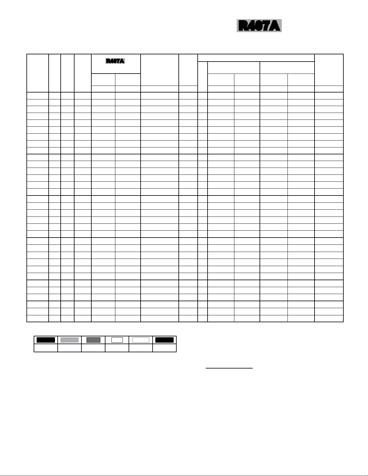
TCL
05/08/15
T50-TCL-PDI-4
- 17 -
GENERAL SPECIFICATIONS -
DOUBLE ROW MODELS
R407A
550 RPM
60Hz
MODEL
NO.
FPI
MAX.
NO. OF
FEEDS
FAN CONFIG.
TCL 029 8 2 x 2 18
TCL 034 10 2 x 2 18
TCL 036 12 2 x 2 18
TCL 039 8 2 x 2 28
TCL 040 10 2 x 2 28
TCL 043 12 2 x 2 28
TCL 044 8 2 x 2 37
TCL 049 10 2 x 2 37
TCL 050 12 2 x 2 37
TCL 056 8 2 x 3 42
TCL 060 10 2 x 3 42
TCL 065 12 2 x 3 42
TCL 066 8 2 x 3 56
TCL 070 10 2 x 3 56
TCL 073 12 2 x 3 56
TCL 076 8 2 x 4 42
TCL 083 10 2 x 4 42
TCL 088 12 2 x 4 42
TCL 086 8 2 x 4 56
TCL 093 10 2 x 4 56
TCL 097 12 2 x 4 56
TCL 094 8 2 x 5 42
TCL 103 10 2 x 5 42
TCL 110 12 2 x 5 42
TCL 108 8 2 x 5 56
TCL 117 10 2 x 5 56
TCL 122 12 2 x 5 56
TCL 127 8 2 x 6 56
TCL 137 10 2 x 6 56
TCL 143 12 2 x 6 56
TCL 149 8 2 x 7 112
TCL 160 10 2 x 7 112
TCL 167 12 2 x 7 112
R407A
REFRIG. CHARGE
(2)
90% FULL
NORMAL
LBS (kg) LBS (kg) CFM (m
15 (7.3) 72 (33) 22300
15 (7.3) 72 (33) 21600
15 (7.3) 72 (33) 22100
22 (10) 100 (45) 21100
22 (10) 100 (45) 20400
22 (10) 100 (45) 20900
26 (12) 125 (57) 21100
26 (12) 125 (57) 20400
26 (12) 125 (57) 19700
30 (13) 146 (66) 33500
30 (13) 146 (66) 32400
30 (13) 146 (66) 31300
42 (19) 190 (87) 31600
42 (19) 190 (87) 30600
42 (19) 190 (87) 29500
64 (29) 323 (147) 43300
64 (29) 323 (147) 41900
64 (29) 323 (147) 40500
80 (36) 419 (190) 40900
80 (36) 419 (190) 39600
80 (36) 419 (190) 38200
84 (39) 411 (187) 54200
84 (39) 411 (187) 52400
84 (39) 411 (187) 50600
105 (47) 531 (242) 51100
105 (47) 531 (242) 49400
105 (47) 531 (242) 47800
121 (55) 628 (285) 61300
121 (55) 628 (285) 59300
121 (55) 628 (285) 57300
138 (63) 724 (329) 71600
138 (63) 724 (329) 69200
138 (63) 724 (329) 66900
(1)
(3)
AIR
FLOW
RATES
(37890)
(36700)
(37550)
(35850)
(34660)
(35510)
(35850)
(34660)
(33470)
(56920)
(55050)
(53180)
(53690)
(51990)
(50120)
(73570)
(71190)
(68810)
(69490)
(67280)
(64900)
(92090)
(89030)
(85970)
(86820)
(83930)
(81210)
(104150)
(100750)
(97350)
(121650)
(117570)
(113660)
SOUND
LEVEL
(5)
3
/h) dBA IN.
48 2
48 2
48 2
48 2
48 2
48 2
48 2
48 2
48 2
50 2
50 2
50 2
50 2
50 2
50 2
51 2
51 2
51 2
51 2
51 2
51 2
52 2
52 2
52 2
52 2
52 2
52 2
53 2
53 2
53 2
53 2
53 2
53 2
QUANTITY
2 1/8
2 1/8
2 1/8
2 1/8
2 1/8
2 1/8
2 1/8
2 1/8
2 1/8
2 5/8
2 5/8
2 5/8
2 5/8
2 5/8
2 5/8
2 5/8
2 5/8
2 5/8
2 5/8
2 5/8
2 5/8
2 5/8
2 5/8
2 5/8
2 5/8
2 5/8
2 5/8
3 1/8
3 1/8
3 1/8
3 1/8
3 1/8
3 1/8
PIPING CONNECTIONS
16°F to 30°F
DESIGN TD
10°F to 15°F
DESIGN TD
INLET OUTLET INLET OUTLET
(mm)
(54)
(54)
(54)
(54)
(54)
(54)
(54)
(54)
(54)
(67)
(67)
(67)
(67)
(67)
(67)
(67)
(67)
(67)
(67)
(67)
(67)
(67)
(67)
(67)
(67)
(67)
(67)
(79)
(79)
(79)
(79)
(79)
(79)
IN.
1 3/8
1 3/8
1 3/8
1 5/8
1 5/8
1 5/8
1 5/8
1 5/8
1 5/8
1 5/8
1 5/8
1 5/8
1 5/8
1 5/8
1 5/8
2 1/8
2 1/8
2 1/8
2 1/8
2 1/8
2 1/8
2 1/8
2 1/8
2 1/8
2 5/8
2 5/8
2 5/8
2 5/8
2 5/8
2 5/8
2 5/8
2 5/8
2 5/8
(mm)
(35)
(35)
(35)
(41)
(41)
(41)
(41)
(41)
(41)
(41)
(41)
(41)
(41)
(41)
(41)
(54)
(54)
(54)
(54)
(54)
(54)
(54)
(54)
(54)
(67)
(67)
(67)
(67)
(67)
(67)
(67)
(67)
(67)
IN.
1 3/8
1 3/8
1 3/8
1 3/8
1 5/8
1 5/8
1 5/8
1 5/8
1 5/8
2 1/8
2 1/8
2 1/8
2 1/8
2 1/8
2 1/8
2 1/8
2 1/8
2 1/8
2 1/8
2 1/8
2 1/8
2 1/8
2 1/8
2 1/8
2 1/8
2 1/8
2 1/8
2 5/8
2 5/8
2 5/8
2 5/8
2 5/8
2 5/8
(mm)
(67)
(67)
(67)
(67)
(67)
(67)
(67)
(67)
(67)
(67)
(67)
(67)
(67)
(67)
(67)
(67)
(67)
(67)
(67)
(67)
(67)
(67)
(67)
(67)
(67)
(67)
(67)
(67)
(67)
(67)
(67)
(67)
(67)
IN.
1 1/8
1 1/8
1 1/8
1 1/8
1 1/8
1 1/8
1 1/8
1 1/8
1 1/8
1 3/8
1 3/8
1 3/8
1 3/8
1 3/8
1 3/8
1 3/8
1 3/8
1 3/8
1 5/8
1 5/8
1 5/8
1 5/8
1 5/8
1 5/8
1 5/8
1 5/8
1 5/8
2 1/8
2 1/8
2 1/8
2 1/8
2 1/8
2 1/8
(mm)
(29)
(29)
(29)
(29)
(29)
(29)
(29)
(29)
(29)
(35)
(35)
(35)
(35)
(35)
(35)
(35)
(35)
(35)
(41)
(41)
(41)
(41)
(41)
(41)
(41)
(41)
(41)
(54)
(54)
(54)
(54)
(54)
(54)
APPROX.
SHIPPING
WEIGHT
LBS (kg)
(568)
1250
(580)
1275
(591)
1300
(602)
1325
(614)
1350
(636)
1400
(659)
1450
(670)
1475
(693)
1525
(920)
2025
(932)
2050
(955)
2100
(989)
2175
(1011)
2225
(1034)
2275
(1216)
2675
(1239)
2725
(1273)
2800
(1318)
2900
(1341)
2950
(1375)
3025
(1534)
3375
(1557)
3425
(1591)
3500
(1659)
3650
(1682)
3700
(1716)
3775
(1977)
4350
(2000)
4400
(2045)
4500
(2295)
5050
(2318)
5100
(2364)
5200
(1) Refrigerant charge conversion factors:
(2) Normal charge is the refrigerant charge for warm ambient or summer operation.
(3) 90% full is the liquid refrigerant weight at 90% of internal volume and is for reference only.
(4) For 50 Hz fan data use 60 Hz CFM (m
(5) Sound pressure level at 30 ft. (10 m) See page 21 for more data
R407C
R404A
R507
R22
R410A
1.0 0.91 0.91 1.05 0.92 1.06
3
/h) X 0.83
R134a
Page 18

TCL
05/08/15
T50-TCL-PDI-4
- 18 -
WIRING DIAGRAM
(SINGLE ROW MODELS - THREE PHASE UNITS)
550/850/1140
60Hz
Page 19

TCL
05/08/15
T50-TCL-PDI-4
- 19 -
WIRING DIAGRAM
(DOUBLE ROW MODELS - THREE PHASE UNITS)
550/850/1140
60Hz
Page 20

TCL
05/08/15
T50-TCL-PDI-4
- 20 -
WIRING DIAGRAM
(MODELS WITH VARIABLE SPEED MOTOR
WITH CONTROLLER ON HEADER FAN)
550/850/1140
60Hz
Page 21

TCL
05/08/15
T50-TCL-PDI-4
- 21 -
85.0
80.0
COMPARATIVE SOUND DATA
(dBA vs. RPM vs. Number of Fans)
UNIT SOUND DAT A
550/850/1140/EC
60Hz
75.0
70.0
65.0
dBA @ 10 ft
60.0
55.0
50.0
0 2 4 6 8 10 12 14 16
NUMBER OF FANS
Data for "E" and "M" models are at 100% fan speed. Further sound reductions can be achieved by control signal modications.
# of Fans
1140 RPM 850 RPM 550 RPM "E" EC MOTOR "M" EC MOTOR
dBA @ 10 ft (3 m)
1 70.3 62.3 53.3 65.3 67.8
2 72.3 64.3 55.3 67.3 69.8
3 73.3 65.3 56.3 68.3 70.8
4 74.3 66.3 57.3 69.3 71.8
5 75.3 67.3 58.3 70.3 72.8
6 76.3 68.3 59.3 71.3 73.8
7 76.8 68.8 59.8 71.8 74.3
8 77.3 69.3 60.3 72.3 74.8
10 78.3 70.3 61.3 73.3 75.8
12 79.3 71.3 62.3 74.3 76.8
14 79.8 71.8 62.8 74.8 77.3
1140 RPM
850 RPM
550 RPM
EC MOTOR
PACKAGE (950
RPM)
EC MOTOR
SHAFTED
(1075 RPM)
Data is typical of "free eld" conditions. Factors such as reecting walls, background noise and installation may have signicant inuence on
data.
Data above is 10 feet from unit. For estimated sound pressures at different distances, use the guide below:
20 feet = above data - 6 dBA 40 feet = above data - 12 dBA 80 feet = above data - 18 dBA
Page 22

TCL
0
2
4
6
8
10
12
14
16
20% 30% 40% 50% 60% 70% 80% 90% 100%
Power Consumpti o n (kW )
Load Requi re ment
POWER CONSUMPTION COMP ARIS O N - 8 FAN E C MOTOR CONDE NSE R vs . 8 FAN 1140 RP M CONDENS ER,
10 FAN 850 RPM CONDNSER & 14 FAN 550 RP M CONDENS ER - (Capacity - 7 5 MBH/TD)
8 FAN 1140 RPM
10 FAN 850 RPM
14 FAN 550 RPM
8 FAN EC MOTOR
TYPICAL
OPERATING
RANGE
05/08/15
T50-TCL-PDI-4
- 22 -
ABOUT EC MOTORS
EC MOTORS
60Hz
Air cooled condensers utilizing electrically commutat-
ed motor (EC motor) technology offer many benets;
Improved Efciency, Reduced Sound Levels, Speed
Control, Simplicity and Reliability
Efciency
The speed control function of an EC motor allows the
condenser to run at optimized energy levels at different operating conditions. Up to 75% in energy savings can be realized when comparing the EC motor
speed control method to a conventional fan cycling
method. See table below for power consumption and
energy savings comparisons.
Sound
As EC motor speeds vary for different operating
conditions they also offer reduced sound levels when
compared to conventional motor running full speed.
Sound levels are reduced on cooler days and in evenings. Refer to page 23 for sound ratings at different
speeds.
Head Pressure Control
EC motors make it easier to maintaining stable head
pressures when motor speeds are varied according to operating conditions. System optimization is
further enhanced compared to the system shock from
conventional cycling banks of fans off and on.
Simplicity and Reliability
The installation and control of EC motors is very
simple compared to other methods of speed control
used on conventional AC motors. Lower running operating temperatures and smooth transitional speed
changes make EC motors durable and reliable.
POWER CONSUMPTION COMPARISON
Page 23

TCL
05/08/15
T50-TCL-PDI-4
- 23 -
CAPACITY DATA -
SINGLE ROW MODELS
EC MOTORS
60Hz
MODEL
NO.
TCL 014 8 1 x 1 6.03 (1.76) 6.22 (1.82) 6.55 (1.92) 6.68 (1.96) 6.35 (1.86) 7
TCL 015 10 1 x 1 6.58 (1.93) 6.79 (1.99) 7.15 (2.10) 7.29 (2.14) 6.94 (2.03) 7
TCL 016 12 1 x 1 7.00 (2.05) 7.23 (2.12) 7.61 (2.23) 7.76 (2.27) 7.38 (2.16) 7
TCL 017 8 1 x 1 7.29 (2.14) 7.52 (2.21) 7.92 (2.32) 8.08 (2.37) 7.68 (2.25) 8
TCL 018 10 1 x 1 7.87 (2.30) 8.12 (2.38) 8.55 (2.51) 8.72 (2.56) 8.29 (2.43) 8
TCL 019 12 1 x 1 8.19 (2.40) 8.46 (2.48) 8.9 (2.61) 9.08 (2.66) 8.63 (2.53) 8
TCL 021 8 1 x 2 9.15 (2.68) 9.45 (2.77) 9.95 (2.92) 10.15 (2.98) 9.65 (2.83) 9
TCL 023 10 1 x 2 10.28 (3.01) 10.61 (3.11) 11.17 (3.27) 11.39 (3.34) 10.83 (3.17) 9
TCL 025 12 1 x 2 11.17 (3.27) 11.53 (3.38) 12.14 (3.56) 12.38 (3.63) 11.78 (3.45) 9
TCL 027 8 1 x 2 12.04 (3.53) 12.44 (3.64) 13.09 (3.84) 13.35 (3.91) 12.70 (3.72) 14
TCL 030 10 1 x 2 13.17 (3.86) 13.59 (3.98) 14.31 (4.19) 14.60 (4.28) 13.88 (4.07) 14
TCL 032 12 1 x 2 14.00 (4.10) 14.46 (4.24) 15.22 (4.46) 15.52 (4.55) 14.76 (4.33) 14
TCL 033 8 1 x 2 14.38 (4.21) 14.85 (4.35) 15.63 (4.58) 15.94 (4.67) 15.16 (4.44) 18
TCL 035 10 1 x 2 15.50 (4.54) 16.01 (4.69) 16.85 (4.94) 17.19 (5.04) 16.34 (4.79) 18
TCL 037 12 1 x 2 16.16 (4.73) 16.68 (4.89) 17.56 (5.15) 17.91 (5.25) 17.03 (4.99) 18
TCL 041 8 1 x 3 18.07 (5.29) 18.66 (5.47) 19.64 (5.76) 20.03 (5.87) 19.05 (5.58) 21
TCL 045 10 1 x 3 19.74 (5.79) 20.39 (5.98) 21.46 (6.29) 21.89 (6.42) 20.82 (6.10) 21
TCL 048 12 1 x 3 21.00 (6.16) 21.69 (6.36) 22.83 (6.69) 23.29 (6.82) 22.15 (6.49) 21
TCL 050 8 1 x 3 21.95 (6.43) 22.67 (6.64) 23.86 (6.99) 24.34 (7.13) 23.14 (6.78) 28
TCL 054 10 1 x 3 23.68 (6.94) 24.45 (7.17) 25.74 (7.54) 26.25 (7.69) 24.97 (7.32) 28
TCL 056 12 1 x 3 24.67 (7.23) 25.47 (7.46) 26.81 (7.86) 27.35 (8.01) 26.01 (7.62) 28
TCL 059 8 1 x 4 25.94 (7.60) 26.79 (7.85) 28.2 (8.26) 28.76 (8.43) 27.35 (8.02) 21
TCL 064 10 1 x 4 28.35 (8.31) 29.28 (8.58) 30.82 (9.03) 31.44 (9.21) 29.90 (8.76) 21
TCL 068 12 1 x 4 30.17 (8.84) 31.15 (9.13) 32.79 (9.61) 33.45 (9.80) 31.81 (9.32) 21
TCL 070 8 1 x 4 30.88 (9.05) 31.88 (9.34) 33.56 (9.84) 34.23 (10.03) 32.55 (9.54) 28
TCL 075 10 1 x 4 33.30 (9.76) 34.39 (10.08) 36.2 (10.61) 36.92 (10.82) 35.11 (10.29) 28
TCL 079 12 1 x 4 34.69 (10.17) 35.82 (10.50) 37.71 (11.05) 38.46 (11.27) 36.58 (10.72) 28
TCL 072 8 1 x 5 31.80 (9.32) 32.83 (9.62) 34.56 (10.13) 35.25 (10.33) 33.52 (9.83) 21
TCL 078 10 1 x 5 34.75 (10.18) 35.88 (10.52) 37.77 (11.07) 38.53 (11.29) 36.64 (10.74) 21
TCL 084 12 1 x 5 36.97 (10.84) 38.17 (11.19) 40.18 (1
TCL 088 8 1 x 5 38.82 (11.38) 40.09 (11.75) 42.2 (12.37) 43.04 (12.62) 40.93 (12.00) 28
TCL 095 10 1 x 5 41.88 (12.27) 43.24 (12.67) 45.52 (13.34) 46.43 (13.61) 44.15 (12.94) 28
TCL 099 12 1 x 5 43.62 (12.79) 45.04 (13.21) 47.41 (13.90) 48.36 (14.18) 45.99 (13.48) 28
TCL 102 8 1 x 6 45.90 (13.45) 47.40 (13.89) 49.89 (14.62) 50.89 (14.91) 48.39 (14.18) 28
TCL 110 10 1 x 6 49.51 (14.51) 51.12 (14.98) 53.81 (15.77) 54.89 (16.09) 52.20 (15.30) 28
TCL 115 12 1 x 6 51.58 (15.12) 53.26 (15.61) 56.06 (16.43) 57.18 (16.76) 54.38 (15.94) 28
TCL 120 8 1 x 7 52.92 (15.51) 54.64 (16.02) 57.52 (16.86) 58.67 (17.20) 55.79 (16.35) 56
TCL 130 10 1 x 7 57.08 (16.73) 58.94 (17.27) 62.04 (18.18) 63.28 (18.54) 60.18 (17.63) 56
TCL 135 12 1 x 7 59.45 (17.42) 61.39 (17.99) 64.62 (18.94) 65.91 (19.32) 62.68 (18.37) 56
FPI
FAN
CONFIG.
R407A
TOTAL HEAT OF REJECTION - MBH (KW) PER 1 °F (0.56 °C) TD MAX.
R407C R404A
R507
1.78) 40.98 (12.02) 38.97 (11.43) 21
R22
R410A
R134a
NO. OF
FEEDS
NOTES:
- Above capacity data based on 0oF subcooling and at sea level.
- For High Altitude applications apply the following correction factors: 0.94 for 2000 feet, 0.88 for 4000 feet and 0.81 for 6000 feet.
- Capacities at other TD within a range of 10 to 30 °F (-12.2 to -1°C) are directly proportional to TD, or use formula: Capacity = Rated capacity ÷ 10 x TD.
- no derate for 50 HZ
- Capacities for R407A and R407C are based on mean temperature. Mean temperature is the average temperature between the saturated condensing
temperatures at the inlet and outlet of the condenser. For dew point ratings, consult factory.
- Capacities are the same for either "E" or "M" models (see Nomenclature, page 2)
Page 24

TCL
05/08/15
T50-TCL-PDI-4
- 24 -
CAPACITY DATA -
DOUBLE ROW MODELS
EC MOTORS
60Hz
MODEL
NO.
TCL 042 8 2 x 2 18.32 (5.37) 18.91 (5.54) 19.91 (5.83) 20.31 (5.95) 19.31 (5.66) 18
TCL 047 10 2 x 2 20.54 (6.02) 21.21 (6.22) 22.33 (6.55) 22.78 (6.68) 21.66 (6.35) 18
TCL 051 12 2 x 2 22.34 (6.55) 23.07 (6.76) 24.28 (7.12) 24.77 (7.26) 23.55 (6.90) 18
TCL 055 8 2 x 2 24.09 (7.06) 24.87 (7.29) 26.18 (7.67) 26.70 (7.83) 25.39 (7.44) 28
TCL 060 10 2 x 2 26.33 (7.72) 27.19 (7.97) 28.62 (8.39) 29.19 (8.55) 27.76 (8.14) 28
TCL 063 12 2 x 2 28.00 (8.21) 28.92 (8.48) 30.44 (8.92) 31.05 (9.10) 29.53 (8.65) 28
TCL 066 8 2 x 2 29.14 (8.54) 30.09 (8.82) 31.67 (9.28) 32.30 (9.47) 30.72 (9.00) 37
TCL 071 10 2 x 2 31.44 (9.21) 32.46 (9.51) 34.17 (10.01) 34.85 (10.21) 33.14 (9.71) 37
TCL 074 12 2 x 2 32.74 (9.60) 33.81 (9.91) 35.59 (10.43) 36.30 (10.64) 34.52 (10.12) 37
TCL 082 8 2 x 3 36.13 (10.59) 37.31 (10.93) 39.27 (11.51) 40.06 (11.74) 38.09 (11.16) 42
TCL 090 10 2 x 3 39.49 (11.57) 40.77 (11.95) 42.92 (12.58) 43.78 (12.83) 41.63 (12.20) 42
TCL 096 12 2 x 3 42.01 (12.31) 43.38 (12.71) 45.66 (13.38) 46.57 (13.65) 44.29 (12.98) 42
TCL 100 8 2 x 3 43.90 (12.87) 45.33 (13.29) 47.72 (13.99) 48.67 (14.27) 46.29 (13.57) 56
TCL 107 10 2 x 3 47.35 (13.88) 48.90 (14.34) 51.47 (15.09) 52.50 (15.39) 49.93 (14.64) 56
TCL 112 12 2 x 3 49.33 (14.45) 50.94 (14.92) 53.62 (15.71) 54.69 (16.02) 52.01 (15.24) 56
TCL 118 8 2 x 4 51.88 (15.21) 53.57 (15.70) 56.39 (16.53) 57.52 (16.86) 54.70 (16.03) 42
TCL 128 10 2 x 4 56.71 (16.62) 58.56 (17.16) 61.64 (18.06) 62.87 (18.42) 59.79 (17.52) 42
TCL 137 12 2 x 4 60.32 (17.68) 62.29 (18.26) 65.57 (19.22) 66.88 (19.60) 63.60 (18.64) 42
TCL 140 8 2 x 4 61.75 (18.10) 63.76 (18.69) 67.12 (19.67) 68.46 (20.06) 65.11 (19.08) 56
TCL 151 10 2 x 4 66.61 (19.52) 68.78 (20.16) 72.4 (21.22) 73.85 (21.64) 70.23 (20.58) 56
TCL 157 12 2 x 4 69.38 (20.33) 71.64 (21.00) 75.41 (22.10) 76.92 (22.54) 73.15 (21.44) 56
TCL 144 8 2 x 5 63.58 (18.64) 65.65 (19.25) 69.11 (20.26) 70.49 (20.67) 67.04 (19.65) 42
TCL 158 10 2 x 5 69.50 (20.37) 71.76 (21.03) 75.54 (22.14) 77.05 (22.58) 73.27 (21.48) 42
TCL 167 12 2 x 5 73.94 (21.67) 76.35 (22.37) 80.37 (23.55) 81.98 (24.02) 77.96 (22.84) 42
TCL 176 8 2 x 5 77.64 (22.75) 80.17 (23.49) 84.39 (24.73) 86.08 (25.22) 81.86 (23.99) 56
TCL 190 10 2 x 5 83.75 (24.55) 86.48 (25.35) 91.03 (26.68) 92.85 (27.21) 88.30 (25.88) 56
TCL 198 12 2 x 5 87.23 (25.57) 90.08 (26.40) 94.82 (27.79) 96.72 (28.35) 91.98 (26.96) 56
TCL 208 8 2 x 6 91.80 (26.90) 94.79 (27.78) 99.78 (29.24) 101.78 (29.82) 96.79 (28.36) 56
TCL 224 10 2 x 6 98.99 (29.02) 102.22 (29.96) 107.6 (31.54) 109.75 (32.17) 104.37 (30.59) 56
TCL 234 12 2 x 6 103.13 (30.23) 106.50 (31.22) 112.1 (32.86) 114.34 (33.52) 108.74 (31.87) 56
TCL 240
TCL 260 10 2 x 7 114.17 (33.45) 117.90 (34.54) 124.1 (36.36) 126.58 (37.09) 120.38 (35.27) 112
TCL 270 12 2 x 7 118.86 (34.85) 122.74 (35.99) 129.2 (37.88) 131.78 (38.64) 125.32 (36.74) 112
FPI
FAN
CONFIG.
8 2 x 7 105.80 (31.01) 109.25 (32.02) 115 (33.71) 117.30 (34.38) 111.55 (32.70) 112
R407A
TOTAL HEAT OF REJECTION - MBH (KW) PER 1 °F (0.56 °C) TD MAX.
R407C R404A
R507
R22
R410A
R134a
NO. OF
FEEDS
NOTES:
- Above capacity data based on 0oF subcooling and at sea level.
- For High Altitude applications apply the following correction factors: 0.94 for 2000 feet, 0.88 for 4000 feet and 0.81 for 6000 feet.
- Capacities at other TD within a range of 10 to 30 °F (-12.2 to -1°C) are directly proportional to TD, or use formula: Capacity = Rated capacity ÷ 10 x TD.
- No derate for 50 HZ.
- Capacities for R407A and R407C are based on mean temperature. Mean temperature is the average temperature between the saturated condensing
temperatures at the inlet and outlet of the condenser. For dew point ratings, consult factory.
- Capacities are the same for either "E" or "M" models (see Nomenclature, page 2)
Page 25

TCL
05/08/15
T50-TCL-PDI-4
- 25 -
ELECTRICAL DATA
208-230/3/60
NO. OF FAN
MOTORS
1 6.2 7.8 15 1750
2 12.4 16.0 20 3500
3 18.6 20.2 25 5250
4 24.8 31.0 35 7000
5 31.0 36.0 40 8750
6 37.2 46.0 50 10500
7 43.4 51.0 60 12250
8 49.6 61.0 70 14000
10 62.0 71.0 80 17500
12 74.4 91.0 100 21000
14 86.8 111.0 125 24500
NO. OF FAN
MOTORS
1 3.1 3.9 15 1750
2 6.2 7.0 15 3500
3 9.3 10.1 15 5250
4 12.4 16.3 20 7000
5 15.5 16.3 20 8750
6 18.6 21.0 25 10500
7 21.7 26.0 30 12250
8 24.8 31.0 35 14000
10 31.0 36.0 40 17500
12 37.2 46.0 50 21000
14 43.4 51.0 60 24500
TOTAL FLA MCA MOP WATTS
460/3/60
TOTAL FLA MCA MOP WATTS
EC MOTORS
60Hz
M.C.A. = Minimum Circuit Ampacity M.O.P. = Maximum Overcurrent Protection
Page 26

TCL
05/08/15
T50-TCL-PDI-4
- 26 -
GENERAL SPECIFICATIONS -
SINGLE ROW MODELS
R407A
EC MOTORS
60Hz
MODEL
NO.
FPI
MAX.
NO.
OF
FEEDS
FAN CONFIG.
TCL 014 8 1 x 1 7
TCL 015 10 1 x 1 7
TCL 016 12 1 x 1 7
TCL 017 8 1 x 1 8
TCL 018 10 1 x 1 8
TCL 019 12 1 x 1 8
TCL 021 8 1 x 2 9
TCL 023 10 1 x 2 9
TCL 025 12 1 x 2 9
TCL 027 8 1 x 2 14
TCL 030 10 1 x 2 14
TCL 032 12 1 x 2 14
TCL 033 8 1 x 2 18
TCL 035 10 1 x 2 18
TCL 037 12 1 x 2 18
TCL 041 8 1 x 3 21
TCL 045 10 1 x 3 21
TCL 048 12 1 x 3 21
TCL 050 8 1 x 3 28
TCL 054 10 1 x 3 28
TCL 056 12 1 x 3 28
TCL 059 8 1 x 4 21
TCL 064 10 1 x 4 21
TCL 068 12 1 x 4 21
TCL 070 8 1 x 4 28
TCL 075 10 1 x 4 28
TCL 079 12 1 x 4 28
TCL 072 8 1 x 5 21
TCL 078 10 1 x 5 21
TCL 084 12 1 x 5 21
TCL 088 8 1 x 5 28
TCL 095 10 1 x 5 28
TCL 099 12 1 x 5 28
TCL 102 8 1 x 6 28
TCL 110 10 1 x 6 28
TCL 115 12 1 x 6 28
TCL 120 8 1 x 7 56
TCL 130 10 1 x 7 56
TCL 135 12 1 x 7 56
R407A
REFRIG.
CHARGE
NORMAL
(2)
LBS (kg) LBS (kg) CFM (m
(1)
90% FULL
(3)
6 (2.5) 25 (12) 11700
6 (2.5) 25 (12) 11300
6 (2.5) 25 (12) 10900
7 (3.1) 32 (14) 11000
7 (3.1) 32 (14) 10700
7 (3.1) 32 (14) 10300
8 (3.6) 36 (17) 24800
8 (3.6) 36 (17) 24000
8 (3.6) 36 (17) 23100
11 (5.1) 50 (23) 23400
11 (5.1) 50 (23) 22600
11 (5.1) 50 (23) 21800
13 (6.1) 63 (29) 22000
13 (6.1) 63 (29) 21300
13 (6.1) 63 (29) 20600
15 (6.8) 73 (33) 35000
15 (6.8) 73 (33) 33900
15 (6.8) 73 (33) 32800
21 (9.4) 96 (43) 33100
21 (9.4) 96 (43) 32000
21 (9.4) 96 (43) 30900
32 (14) 162 (74) 45400
32 (14) 162 (74) 43900
32 (14) 162 (74) 42400
41 (19) 210 (96) 42800
41 (19) 210 (96) 41400
41 (19) 210 (96) 40000
42 (19) 206 (94) 56700
42 (19) 206 (94) 54900
42 (19) 206 (94) 53000
53 (24) 266 (121) 53500
53 (24) 266 (121) 51800
53 (24) 266 (121) 50000
61 (28) 314 (143) 64200
61 (28) 314 (143) 62100
61 (28) 314 (143) 60000
69 (31) 362 (165) 74900
69 (31) 362 (165) 72500
69 (31) 362 (165) 70000
AIR
FLOW
RATES
(19880)
(19200)
(18520)
(18690)
(18180)
(17500)
(42140)
(40780)
(39250)
(39760)
(38400)
(37040)
(37380)
(36190)
(35000)
(59470)
(57600)
(55730)
(56240)
(54370)
(52500)
(77130)
(74590)
(72040)
(72720)
(70340)
(67960)
(96330)
(93280)
(90050)
(90900)
(88010)
(84950)
(109080)
(105510)
(101940)
(127260)
(123180)
(118930)
SOUND
LEVEL
"E" "M"
3
/h) dBA dBA
65 68
65 68
65 68
65 68
65 68
65 68
67 70
67 70
67 70
67 70
67 70
67 70
67 70
67 70
67 70
68 71
68 71
68 71
68 71
68 71
68 71
69 72
69 72
69 72
69 72
69 72
69 72
70 73
70 73
70 73
70 73
70 73
70 73
71 74
71 74
71 74
71 74
71 74
71 74
(4)
PIPING CONNECTIONS
16°F to 30°F
DESIGN TD
10°F to 15°F
DESIGN TD
INLET OUTLET INLET OUTLET
QUANTITY
1
1
1
1
1
1
1
1
1
1
1
1
1
1
1
1
1
1
1
1
1
1
1
1
1
1
1
1
1
1
1
1
1
1
1
1
1
1
1
IN.
1 5/8
1 5/8
1 5/8
1 5/8
1 5/8
1 5/8
2 1/8
2 1/8
2 1/8
2 1/8
2 1/8
2 1/8
2 1/8
2 1/8
2 1/8
2 5/8
2 5/8
2 5/8
2 5/8
2 5/8
2 5/8
2 5/8
2 5/8
2 5/8
2 5/8
2 5/8
2 5/8
3 1/8
3 1/8
3 1/8
3 1/8
3 1/8
3 1/8
3 1/8
3 1/8
3 1/8
3 1/8
3 1/8
3 1/8
(mm)
(41)
(41)
(41)
(41)
(41)
(41)
(54)
(54)
(54)
(54)
(54)
(54)
(54)
(54)
(54)
(67)
(67)
(67)
(67)
(67)
(67)
(67)
(67)
(67)
(67)
(67)
(67)
(79)
(79)
(79)
(79)
(79)
(79)
(79)
(79)
(79)
(79)
(79)
(79)
IN.
1 1/8
1 1/8
1 1/8
1 1/8
1 1/8
1 1/8
1 3/8
1 3/8
1 3/8
1 5/8
1 5/8
1 5/8
1 5/8
1 5/8
1 5/8
1 5/8
1 5/8
1 5/8
2 1/8
2 1/8
2 1/8
2 1/8
2 1/8
2 1/8
2 1/8
2 1/8
2 1/8
2 5/8
2 5/8
2 5/8
2 5/8
2 5/8
2 5/8
2 5/8
2 5/8
2 5/8
2 5/8
2 5/8
2 5/8
(mm)
(29)
(29)
(29)
(29)
(29)
(29)
(35)
(35)
(35)
(41)
(41)
(41)
(41)
(41)
(41)
(41)
(41)
(41)
(54)
(54)
(54)
(54)
(54)
(54)
(54)
(54)
(54)
(67)
(67)
(67)
(67)
(67)
(67)
(67)
(67)
(67)
(67)
(67)
(67)
IN.
1 3/8
1 3/8
1 3/8
1 3/8
1 3/8
1 3/8
1 3/8
1 3/8
1 3/8
1 5/8
1 5/8
1 5/8
1 5/8
1 5/8
1 5/8
2 1/8
2 1/8
2 1/8
2 1/8
2 1/8
2 1/8
2 1/8
2 1/8
2 1/8
2 1/8
2 1/8
2 1/8
2 5/8
2 5/8
2 5/8
2 5/8
2 5/8
2 5/8
3 1/8
3 1/8
3 1/8
3 1/8
3 1/8
3 1/8
(mm)
(35)
(35)
(35)
(35)
(35)
(35)
(35)
(35)
(35)
(41)
(41)
(41)
(41)
(41)
(41)
(54)
(54)
(54)
(54)
(54)
(54)
(54)
(54)
(54)
(54)
(54)
(54)
(67)
(67)
(67)
(67)
(67)
(67)
(79)
(79)
(79)
(79)
(79)
(79)
IN.
7/8
7/8
7/8
7/8
7/8
7/8
1 1/8
1 1/8
1 1/8
1 1/8
1 1/8
1 1/8
1 1/8
1 1/8
1 1/8
1 3/8
1 3/8
1 3/8
1 5/8
1 5/8
1 5/8
1 5/8
1 5/8
1 5/8
1 5/8
1 5/8
1 5/8
2 1/8
2 1/8
2 1/8
2 1/8
2 1/8
2 1/8
2 1/8
2 1/8
2 1/8
2 5/8
2 5/8
2 5/8
(mm)
(22)
(22)
(22)
(22)
(22)
(22)
(29)
(29)
(29)
(29)
(29)
(29)
(29)
(29)
(29)
(35)
(35)
(35)
(41)
(41)
(41)
(41)
(41)
(41)
(41)
(41)
(41)
(54)
(54)
(54)
(54)
(54)
(54)
(54)
(54)
(54)
(67)
(67)
(67)
APPROX.
SHIPPING
WEIGHT
LBS (kg)
(161)
355
(164)
360
(168)
370
(173)
380
(177)
390
(182)
400
(302)
665
(305)
670
(309)
680
(323)
710
(327)
720
(336)
740
(350)
770
(355)
780
(364)
800
(477)
1050
(489)
1075
(500)
1100
(523)
1150
(534)
1175
(545)
1200
(648)
1425
(659)
1450
(670)
1475
(693)
1525
(705)
1550
(727)
1600
(784)
1725
(818)
1800
(841)
1850
(875)
1925
(886)
1950
(909)
2000
(1034)
2275
(1045)
2300
(1068)
2350
(1216)
2675
(1227)
2700
(1250)
2750
(1) Refrigerant charge conversion factors:
(2) Normal charge is the refrigerant charge for warm ambient or summer operation.
(3) 90% full is the liquid refrigerant weight at 90% of internal volume and is for reference only.
(4) Sound pressure level at 30 ft. (10 m) See page 21 for more data
R407C R404A
R507
R22
R410A
1.0 0.91 0.91 1.05 0.92 1.06
R134a
Page 27

TCL
05/08/15
T50-TCL-PDI-4
- 27 -
GENERAL SPECIFICATIONS -
SINGLE ROW MODELS
R407A
EC MOTORS
60Hz
MODEL
NO.
FPI
MAX.
NO.
OF
FEEDS
FAN CONFIG.
TCL 042 8 2 x 2 18
TCL 047 10 2 x 2 18
TCL 051 12 2 x 2 18
TCL 055 8 2 x 2 28
TCL 060 10 2 x 2 28
TCL 063 12 2 x 2 28
TCL 066 8 2 x 2 37
TCL 071 10 2 x 2 37
TCL 074 12 2 x 2 37
TCL 082 8 2 x 3 42
TCL 090 10 2 x 3 42
TCL 096 12 2 x 3 42
TCL 100 8 2 x 3 56
TCL 107 10 2 x 3 56
TCL 112 12 2 x 3 56
TCL 118 8 2 x 4 42
TCL 128 10 2 x 4 42
TCL 137 12 2 x 4 42
TCL 140 8 2 x 4 56
TCL 151 10 2 x 4 56
TCL 157 12 2 x 4 56
TCL 144 8 2 x 5 42
TCL 158 10 2 x 5 42
TCL 167 12 2 x 5 42
TCL 176 8 2 x 5 56
TCL 190 10 2 x 5 56
TCL 198 12 2 x 5 56
TCL 208 8 2 x 6 56
TCL 224 10 2 x 6 56
TCL 234 12 2 x 6 56
TCL 240 8 2 x 7 112
TCL 260 10 2 x 7 112
TCL 270 12 2 x 7 112
R407A
REFRIG.
CHARGE
NORMAL
(2)
LBS (kg) LBS (kg) CFM (m
15 (7.3) 72 (33) 49500
15 (7.3) 72 (33) 47900
15 (7.3) 72 (33) 46300
22 (10) 100 (45) 46700
22 (10) 100 (45) 45200
22 (10) 100 (45) 43700
26 (12) 125 (57) 44100
26 (12) 125 (57) 42600
26 (12) 125 (57) 41200
30 (13) 146 (66) 70100
30 (13) 146 (66) 67800
30 (13) 146 (66) 65500
42 (19) 190 (87) 66100
42 (19) 190 (87) 64000
42 (19) 190 (87) 61800
64 (29) 323 (147) 90700
64 (29) 323 (147) 87800
64 (29) 323 (147) 84800
80 (36) 419 (190) 85600
80 (36) 419 (190) 82800
80 (36) 419 (190) 80000
84 (39) 411 (187) 113400
84 (39) 411 (187) 109700
84 (39) 411 (187) 106000
105 (47) 531 (242) 107000
105 (47) 531 (242) 103500
105 (47) 531 (242) 100000
121 (55) 628 (285) 128400
121 (55) 628 (285) 124200
121 (55) 628 (285) 120000
138 (63) 724 (329) 149800
138 (63) 724 (329) 144900
138 (63) 724 (329) 140000
(1)
90% FULL
(3)
AIR
FLOW
RATES
(84100)
(81380)
(78660)
(79340)
(76790)
(74250)
(74930)
(72380)
(70000)
(119100)
(115190)
(111280)
(112300)
(108740)
(105000)
(154100)
(149170)
(144080)
(145430)
(140680)
(135920)
(192670)
(186380)
(180090)
(181790)
(175850)
(169900)
(218150)
(211020)
(203880)
(254510)
(246190)
(237860)
"E"
3
/h) dBA
SOUND
(4)
LEVEL
"M"
dBA
69 72 2
69 72 2
69 72 2
69 72 2
69 72 2
69 72 2
69 72 2
69 72 2
69 72 2
71 74 2
71 74 2
71 74 2
71 74 2
71 74 2
71 74 2
72 75 2
72 75 2
72 75 2
72 75 2
72 75 2
72 75 2
73 76 2
73 76 2
73 76 2
73 76 2
73 76 2
73 76 2
74 77 2
74 77 2
74 77 2
75 77 2
75 77 2
75 77 2
PIPING CONNECTIONS
16°F to 30°F
DESIGN TD
10°F to 15°F
DESIGN TD
INLET OUTLET INLET OUTLET
QUANTITY
IN.
2 1/8
2 1/8
2 1/8
2 1/8
2 1/8
2 1/8
2 1/8
2 1/8
2 1/8
2 5/8
2 5/8
2 5/8
2 5/8
2 5/8
2 5/8
2 5/8
2 5/8
2 5/8
2 5/8
2 5/8
2 5/8
3 1/8
3 1/8
3 1/8
3 1/8
3 1/8
3 1/8
3 1/8
3 1/8
3 1/8
3 1/8
3 1/8
3 1/8
(mm)
(54)
(54)
(54)
(54)
(54)
(54)
(54)
(54)
(54)
(67)
(67)
(67)
(67)
(67)
(67)
(67)
(67)
(67)
(67)
(67)
(67)
(79)
(79)
(79)
(79)
(79)
(79)
(79)
(79)
(79)
(79)
(79)
(79)
IN.
1 3/8
1 3/8
1 3/8
1 5/8
1 5/8
1 5/8
1 5/8
1 5/8
1 5/8
1 5/8
1 5/8
1 5/8
2 1/8
2 1/8
2 1/8
2 1/8
2 1/8
2 1/8
2 1/8
2 1/8
2 1/8
2 5/8
2 5/8
2 5/8
2 5/8
2 5/8
2 5/8
2 5/8
2 5/8
2 5/8
2 5/8
2 5/8
2 5/8
(mm)
(35)
(35)
(35)
(41)
(41)
(41)
(41)
(41)
(41)
(41)
(41)
(41)
(54)
(54)
(54)
(54)
(54)
(54)
(54)
(54)
(54)
(67)
(67)
(67)
(67)
(67)
(67)
(67)
(67)
(67)
(67)
(67)
(67)
IN.
1 3/8
1 3/8
1 3/8
1 5/8
1 5/8
1 5/8
1 5/8
1 5/8
1 5/8
2 1/8
2 1/8
2 1/8
2 1/8
2 1/8
2 1/8
2 1/8
2 1/8
2 1/8
2 1/8
2 1/8
2 1/8
2 5/8
2 5/8
2 5/8
2 5/8
2 5/8
2 5/8
3 1/8
3 1/8
3 1/8
3 1/8
3 1/8
3 1/8
(mm)
(35)
(35)
(35)
(41)
(41)
(41)
(41)
(41)
(41)
(54)
(54)
(54)
(54)
(54)
(54)
(54)
(54)
(54)
(54)
(54)
(54)
(67)
(67)
(67)
(67)
(67)
(67)
(79)
(79)
(79)
(79)
(79)
(79)
IN.
1 1/8
1 1/8
1 1/8
1 1/8
1 1/8
1 1/8
1 1/8
1 1/8
1 1/8
1 3/8
1 3/8
1 3/8
1 5/8
1 5/8
1 5/8
1 5/8
1 5/8
1 5/8
1 5/8
1 5/8
1 5/8
2 1/8
2 1/8
2 1/8
2 1/8
2 1/8
2 1/8
2 1/8
2 1/8
2 1/8
2 5/8
2 5/8
2 5/8
(mm)
(29)
(29)
(29)
(29)
(29)
(29)
(29)
(29)
(29)
(35)
(35)
(35)
(41)
(41)
(41)
(41)
(41)
(41)
(41)
(41)
(41)
(54)
(54)
(54)
(54)
(54)
(54)
(54)
(54)
(54)
(67)
(67)
(67)
APPROX.
SHIPPING
WEIGHT
LBS (kg)
(568)
1250
(580)
1275
(591)
1300
(602)
1325
(614)
1350
(636)
1400
(659)
1450
(670)
1475
(693)
1525
(920)
2025
(932)
2050
(955)
2100
(989)
2175
(1011)
2225
(1034)
2275
(1216)
2675
(1239)
2725
(1273)
2800
(1318)
2900
(1341)
2950
(1375)
3025
(1534)
3375
(1557)
3425
(1591)
3500
(1659)
3650
(1682)
3700
(1716)
3775
(1977)
4350
(2000)
4400
(2045)
4500
(2295)
5050
(2318)
5100
(2364)
5200
(1) Refrigerant charge conversion factors:
(2) Normal charge is the refrigerant charge for warm ambient or summer operation.
(3) 90% full is the liquid refrigerant weight at 90% of internal volume and is for reference only.
(4) Sound pressure level at 30 ft. (10 m) See page 21 for more data
R407C R404A
R507
R22
R410A
1.0 0.91 0.91 1.05 0.92 1.06
R134a
Page 28

TCL
!
05/08/15
T50-TCL-PDI-4
- 28 -
EC MOTOR APPLICATION
EC MOTORS
60Hz
Motors With Built-in Variable Speed –
Optional “E” or "M" Fan/Motor Code
(see Nomenclature,pg. 2)
Units with an "E" motor designation use an EC (electronically commutated) motor / fan combination to provide
variable speed condenser control. Units with a "M" motor designation use EC motor only with a removeable fan
blade. Ideally the motors on the condenser should all be
EC and simultaneously slow down/speed up together. This
provides for maximum energy savings. However some
applications may exist where just the last fan or pair of
fans (ones closest to header) are solely EC motors. (The
remaining conventional type motors are then cycled off by
fan cycling pressure controls).
Important Warnings:
(Please read before handling motors)
1. When connecting the unit to the power supply,
dangerous voltages occur. Due to motor
capacitor discharge time, do not open the motor
within 5 minutes after disconnection of all phases.
2. With a Control voltage fed in or a set speed value
being saved, the motor will restart automatically
after a power failure.
3. Dangerous external voltages can be present at the
motor terminals even when the unit is turned off.
4. The Electronics housing can get hot.
5. The cycling on and off of EC motors should be
controlled by the DC control voltage (i.e. 10V DC
will turn motor off). Excessive cycling of the motor by
line voltage contactors may cause stress on the motors
and reduce the motor life.
Speed Adjustment Characteristics
The EC motor varies its speed linearly based on a 10-0V
input signal. At 0 VDC, the motor runs at full speed. At
10 VDC, the motor turns off. A chart of the speed control
curve is shown below. The motor can be controlled at any
speed below its nominal RPM.
Full
RPM
RPM
OFF
10
Control Voltage (V dc)
Control Signal
The input control signal can be supplied by an external
control signal or from a factory installed proportional
pressure control. Units with factory installed proportional
pressure controls require no installation wiring and are
adjusted with initial factory settings. These may require
further adjustments to suit local eld conditions.
External Control Signal (Supplied by others)
Contact control manufacturer for setup of external controller to provide a 10-0 VDC control signal. Wire the control
signal to terminal board in unit control box. Refer to the
condenser EC wiring diagram for typical external signal
control wiring.
Page 29

TCL
05/08/15
T50-TCL-PDI-4
- 29 -
EC MOTOR WIRING
(DOUBLE ROW MODELS -
ECM "M" w/ OPTIONAL PROPORTIONAL PRESSURE CONTROL)
EC MOTORS
60Hz
Page 30

TCL
05/08/15
T50-TCL-PDI-4
- 30 -
EC MOTOR WIRING
(DOUBLE ROW MODELS -
ECM "E" w/ OPTIONAL PROPORTIONAL PRESSURE CONTROL)
EC MOTORS
60Hz
Page 31

DIMENSIONAL DATA -
(1121)
05/08/15
T50-TCL-PDI-4
- 31 -
TCL 60Hz
SIDE VIEWS
REFER TO
FACING PAGE
FOR DETAILS
VERTICAL AIR FLOW MODELS
L
2 (51)
(203)
8
M1
L
(203)
2 (51)
8
(203)
2 (51)
8
L
M2
(203)
8
2 (51)
(203)
2 (51)
8
(203)
8
M1
M1 M2
2 (51)
8
(203)
SINGLE ROW MODELS DOUBLE ROW MODELS
1 1/2
(38)
28 1/2
(724)
44 5/8 (1133)
ELECTRICAL
1 1/2
(38)
28 1/2
(724)
END
24
(610)
2 (51)
(203)
(203)
2 (51)
8
24 1/8
8
(613)
44 1/8
(1121)
VIEW
24
(610)
2 (51)
(203)
8
86 1/8
(2188)
86 5/8
(2200)
66 1/8
(1680)
2 (51)
(203)
2 (51)
8
(203)
M3
2 (51)
8
(203)
2 (51)
8
2 (51) 2 (51)
(203)
24 1/8
(613)
44 1/8
(203)
8
8
PIPING
END
VIEW
2 (51)
(203)
8
86 1/8
(2188)
66 1/8
(1680)
(203)
2 (51)
8
Page 32

DIMENSIONAL DATA -
05/08/15
T50-TCL-PDI-4
- 32 -
TCL 60Hz
VERTICAL AIR FLOW MODELS
SINGLE ROW MODELS
MODEL NUMBER / RPM
850 1140 / EC 550 In. mm In. mm In. mm In. mm
TCL 012 TCL 015 TCL 014 TCL 017 TCL 007 TCL 010
TCL 013 TCL 016 TCL 015 TCL 018 TCL 008 TCL 011
TCL 014 TCL 017 TCL 016 TCL 019 TCL 009 TCL 012
TCL 019 TCL 028 TCL 021 TCL 032 TCL 014 TCL 022
TCL 021 TCL 029 TCL 023 TCL 033 TCL 016 TCL 021
TCL 023 TCL 031 TCL 025 TCL 035 TCL 018 TCL 023
TCL 024 TCL 032 TCL 027 TCL 037 TCL 019 TCL 024
TCL 027 TCL 030 TCL 020
TCL 037 TCL 043 TCL 041 TCL 050 TCL 028 TCL 033
TCL 042 TCL 049 TCL 048 TCL 056 TCL 032 TCL 037
TCL 051 TCL 060 TCL 059 TCL 070 TCL 038 TCL 042
TCL 059 TCL 067 TCL 068 TCL 079 TCL 045 TCL 048
TCL 063 TCL 075 TCL 072 TCL 088 TCL 047 TCL 054
TCL 073 TCL 084 TCL 084 TCL 099 TCL 055 TCL 061
TCL 089 TCL 100 TCL 102 TCL 115 TCL 064 TCL 071
TCL 096 TCL 110 TCL 069
TCL 102 TCL 115 TCL 120 TCL 135 TCL 074 TCL 084
TCL 111 TCL 130 TCL 080
DOUBLE ROW MODELS
FAN
CONFIG.
1 x 1 57 ½ 1460 37 940 - - - -
1 x 2 112 ½ 2857 92 2337 - - - -
1 x 3 167 ½ 4254 147 3734 - - - -TCL 040 TCL 047 TCL 045 TCL 054 TCL 031 TCL 035
1 x 4 222 ½ 5651 92 2337 102 2591 - -TCL 056 TCL 064 TCL 064 TCL 075 TCL 041 TCL 046
1 x 5 277 ½ 7048 92 2337 47 1194 102 2591TCL 069 TCL 081 TCL 078 TCL 095 TCL 051 TCL 058
1 x 6 332 ½ 8445 92 2337 102 2591 102 2591
1 x 7 387 ½ 9842 92 2337 157 3988 102 2591
L M1 M2 M3
MODEL NUMBER / RPM
850 1140 / EC 550 In. mm In. mm In. mm In. mm
TCL 038 TCL 057 TCL 042 TCL 063 TCL 029 TCL 043
TCL 041 TCL 058 TCL 047 TCL 066 TCL 034 TCL 044
TCL 046 TCL 062 TCL 051 TCL 071 TCL 036 TCL 049
TCL 048 TCL 065 TCL 055 TCL 074 TCL 039 TCL 050
TCL 054 TCL 060 TCL 040
TCL 072 TCL 087 TCL 082 TCL 100 TCL 056 TCL 066
TCL 085 TCL 097 TCL 096 TCL 112 TCL 065 TCL 073
TCL 103 TCL 120 TCL 118 TCL 140 TCL 076 TCL 086
TCL 119 TCL 134 TCL 137 TCL 157 TCL 088 TCL 097
TCL 126 TCL 150 TCL 144 TCL 176 TCL 094 TCL 108
TCL 138 TCL 162 TCL 158 TCL 190 TCL 103 TCL 117
TCL 146 TCL 168 TCL 167 TCL 198 TCL 110 TCL 122
TCL 178 TCL 200 TCL 208 TCL 234 TCL 127 TCL 143
TCL 192 TCL 224 TCL 137
TCL 205 TCL 230 TCL 240 TCL 270 TCL 149 TCL 167
TCL 221 TCL 260 TCL 160
FAN
CONFIG.
2 x 2 112 ½ 2857 92 2337 - - - -
2 x 3 167 ½ 4254 147 3734 - - - -TCL 080 TCL 094 TCL 090 TCL 107 TCL 060 TCL 070
2 x 4 222 ½ 5651 92 2337 102 2591 - -TCL 112 TCL 129 TCL 128 TCL 151 TCL 083 TCL 093
2 x 5 277 ½ 7048 92 2337 47 1194 102 2591
2 x 6 332 ½ 8445 92 2337 102 2591 102 2591
2 x 7 387 ½ 9842 92 2337 157 3988 102 2591
L M1 M2 M3
Page 33

DIMENSIONAL DATA -
05/08/15
T50-TCL-PDI-4
- 33 -
TCL 60Hz
L
M1
HORIZONTAL AIR FLOW MODELS
REFER TO
FACING PAGE
FOR DETAILS
L
2 7/8 (73)
8 (203)
37 (940)
58 3/4 (1492)
49 5/8
(1260)
2 7/8 (73)
8 (203)
91 5/8
(2327)
30 1/8
M1
L
L
L
M2
M2M1
M2M1
M3
(765)
45 1/4 (1149)
2 3/8 DIA.
LIFTING
HOLES
ANGLE BRACES:
CENTRE LEGS ONLY
4 - 7 FAN SINGLE FAN
WIDE MODELS
AND EVERY LEG ON
DOUBLE FAN WIDE
MODELS
M1
M2
M2
M2
M3
Page 34

DIMENSIONAL DATA -
05/08/15
T50-TCL-PDI-4
- 34 -
TCL 60Hz
HORIZONTAL AIR FLOW MODELS
SINGLE ROW MODELS
MODEL NUMBER / RPM
850 1140 / EC 550 In. mm In. mm In. mm In. mm
TCL 012 TCL 015 TCL 014 TCL 017 TCL 007 TCL 010
TCL 013 TCL 016 TCL 015 TCL 018 TCL 008 TCL 011
TCL 014 TCL 017 TCL 016 TCL 019 TCL 009 TCL 012
TCL 019 TCL 028 TCL 021 TCL 032 TCL 014 TCL 022
TCL 021 TCL 029 TCL 023 TCL 033 TCL 016 TCL 021
TCL 023 TCL 031 TCL 025 TCL 035 TCL 018 TCL 023
TCL 024 TCL 032 TCL 027 TCL 037 TCL 019 TCL 024
TCL 027 TCL 030 TCL 020
TCL 037 TCL 043 TCL 041 TCL 050 TCL 028 TCL 033
TCL 042 TCL 049 TCL 048 TCL 056 TCL 032 TCL 037
TCL 051 TCL 060 TCL 059 TCL 070 TCL 038 TCL 042
TCL 059 TCL 067 TCL 068 TCL 079 TCL 045 TCL 048
TCL 063 TCL 075 TCL 072 TCL 088 TCL 047 TCL 054
TCL 073 TCL 084 TCL 084 TCL 099 TCL 055 TCL 061
TCL 089 TCL 100 TCL 102 TCL 115 TCL 064 TCL 071
TCL 096 TCL 110 TCL 069
TCL 102 TCL 115 TCL 120 TCL 135 TCL 074 TCL 084
TCL 111 TCL 130 TCL 080
FAN
CONFIG.
1 x 1 57 ½ 1460 55 7/8 1397 - - - -
1 x 2 112 ½ 2857 110 7/8 2816 - - - -
1 x 3 167 ½ 4254 85 2159 85 7/8 2181 - -TCL 040 TCL 047 TCL 045 TCL 054 TCL 031 TCL 035
1 x 4 222 ½ 5651 110 2794 110 7/8 2816 - -TCL 056 TCL 064 TCL 064 TCL 075 TCL 041 TCL 046
1 x 5 277 ½ 7048 110 2794 55 1397
1 x 6 332 ½ 8445 110 2794 110 2794
1 x 7 387 ½ 9842 110 2794 55 1397 102 2591
L M1 M2 M3
DOUBLE ROW MODELS
110 7/8
110 7/8
2816TCL 069 TCL 081 TCL 078 TCL 095 TCL 051 TCL 058
2816
MODEL NUMBER / RPM
850 1140 / EC 550 In. mm In. mm In. mm In. mm
TCL 038 TCL 057 TCL 042 TCL 063 TCL 029 TCL 043
TCL 041 TCL 058 TCL 047 TCL 066 TCL 034 TCL 044
TCL 046 TCL 062 TCL 051 TCL 071 TCL 036 TCL 049
TCL 048 TCL 065 TCL 055 TCL 074 TCL 039 TCL 050
TCL 054 TCL 060 TCL 040
TCL 072 TCL 087 TCL 082 TCL 100 TCL 056 TCL 066
TCL 085 TCL 097 TCL 096 TCL 112 TCL 065 TCL 073
TCL 103 TCL 120 TCL 118 TCL 140 TCL 076 TCL 086
TCL 119 TCL 134 TCL 137 TCL 157 TCL 088 TCL 097
TCL 126 TCL 150 TCL 144 TCL 176 TCL 094 TCL 108
TCL 138 TCL 162 TCL 158 TCL 190 TCL 103 TCL 117
TCL 146 TCL 168 TCL 167 TCL 198 TCL 110 TCL 122
TCL 178 TCL 200 TCL 208 TCL 234 TCL 127 TCL 143
TCL 192 TCL 224 TCL 137
TCL 205 TCL 230 TCL 240 TCL 270 TCL 149 TCL 167
TCL 221 TCL 260 TCL 160
FAN
CONFIG.
2 x 2 112 ½ 2857 110 7/8 2816 - - - -
2 x 3 167 ½ 4254 85 2159 85 7/8 2181 - -TCL 080 TCL 094 TCL 090 TCL 107 TCL 060 TCL 070
2 x 4 222 ½ 5651 110 2794 110 7/8 2816 - -TCL 112 TCL 129 TCL 128 TCL 151 TCL 083 TCL 093
2 x 5 277 ½ 7048 110 2794 55 1397 110 7/8 2816
2 x 6 332 ½ 8445 110 2794 110 2794 110 7/8 2816
2 x 7 387 ½ 9842 110 2794 55 1397 102 2591
L M1 M2 M3
Page 35

CONDENSER THEORY
05/08/15
T50-TCL-PDI-4
- 35 -
TCL 60Hz
The condenser rst desuperheats the vapor down to its
THE BASIC REFRIGERATION CYCLE
The purpose of a refrigeration system is to absorb heat
from an area where it is not wanted and reject this heat
to an area where it is unobjectionable. By referring to the
diagram below, it can be seen that only a few components
are required to perform this task.
saturation point. This saturation point can be expressed as
the condensing temperature of the refrigerant and varies
with condenser size, load and ambient temperature.
Now the condenser must remove the latent heat of condensation from the refrigerant so that it may fully condense. After the refrigerant has fully condensed, it will be
subcooled to some extent.The liquid leaving the condenser
is still at a high pressure but at a much lower temperature and drains into the receiver. As the liquid level in the
receiver increases, the vapor is allowed to vent back up to
the condenser via \the condensate line.
Because the dip tube almost reaches the bottom of the
receiver, only liquid will enter the liquid line. This liquid now
passes through the metering device where its pressure
is reduced to the evaporating pressure. The temperature
will drop with pressure since the refrigerant will always attempt to meet its saturation point during a change of state.
High pressure/high temperature vapor leaves the compressor and is forced into the condenser via the discharge line.
GLOSSARY OF TERMS
Balance point - after a system stabilizes, the heat added
to the refrigerant during the refrigeration cycle will equal
the heat rejected at the condenser. The balance point usually refers to the actual TD that the system is operating at.
The balance point could refer to a low side balance or a
high side balance. For example, a system operating with a
120 oF (48.9 oC) condensing temperature in a 90 oF (32.2
o
C) ambient will have a condenser balance point of 30 oF
(-1.1 oC) TD.
Circuit - a circuit can be considered a group of feeds. A
condenser may be sized to handle several refrigeration
systems at one time. Each system is considered one circuit
and the number of feeds required for each circuit depends
on the THR for that particular system. Each circuit has its
own inlet and outlet header. The number of circuits on a
condenser can not exceed the total number of feeds available.
Compression Ratio - Compression ratio equals the discharge pressure in pounds per square inch absolute (psia)
divided by the suction pressure in psia. The compression
ratio in a compressor increases as suction pressure decreases and as discharge pressure increases. (at sea-
level, psia is equal to psig plus 14.7).
Compressor Capacity - can be dened as the actual
refrigerating capacity available at the evaporator and suction line after considering the overall system balance point.
Compressor capacity is mainly affected by the evaporating
and condensing temperatures of the system.
The condensing temperature decreases as the
ambient temperature drops and/or as the condenser
surface increases.
the receiver. The condensate line should drop vertically
and is typically larger than the liquid line. This is to promote
free draining of the refrigerant from the condenser to the
receiver.
Condenser Temperature Difference (TD) - is the difference between the condensing temperature of the refrigerant and the temperature of the air entering the condenser.
Condensing Temperature (CT) - is the temperature
where the refrigerant vapor condenses back to a liquid.
This temperature varies with condenser size. Condensing
temperature should be kept as low as possible to maintain
higher refrigerating capacity and system efciency
Desuperheat - refers to the lowering of refrigerant super-
heat. Hot vapor entering a condenser must rst be desuperheated before any condensing of the refrigerant can
take place.
Evaporating Temperature - the temperature at which heat
is absorbed in the evaporator, at this temperature, the refrigerant changes from a liquid to a vapor. This evaporating
temperature is dependent on pressure and must be lower
than the surrounding temperature for heat transfer to take
place.
Feed - a single path for refrigerant ow inside a condenser.
This path begins at the inlet header and terminates at the
condenser’s outlet header. These feeds can be grouped
together to accommodate one or more circuits.
Condensate Line - (also called “Drain Leg”) is a term that
describes the refrigerant line between the condenser and
Page 36

GLOSSARY OF TERMS (cont'd)
05/08/15
T50-TCL-PDI-4
- 36 -
TCL 60Hz
Heat of Compression - heat is added to the refrigerant as
it is compressed. Evidence of this can be observed on the
pressure-enthalpy diagram for the refrigerant being used.
The amount of this heat is dependent on the refrigerant
type and compression ratio.
Additional heat from friction also increases the heat of
compression. All of this heat along with the heat absorbed
in the evaporator, suction line and any motor heat must be
rejected by the condenser.
Latent Heat of Vaporization (also Latent Heat of Condensation) - refers to the heat required to fully vaporize or
condense a refrigerant. This latent heat varies with temperature and pressure. Latent heat is often referred to as
hidden heat since adding heat to a saturated liquid or removing heat from a saturated vapor will result in a change
of state and heat content but not a change in temperature.
Liquid Line - is the piping between the receiver and the
metering device. On systems without a receiver, the liquid
line runs between the condenser and the metering device.
Open Drive - This term is given to a compressor where its
driving motor is separate from the compressor. In this type
of compressor, motor heat is not transferred to the refrigerant.
Refrigerating Effect - the total amount of heat absorbed
by the evaporator. This heat includes both latent heat and
superheat. This value is usually expressed in BTU/Hour,
(BTUH), or 1000 BTU/Hour (MBH)
Saturation - occurs whenever the refrigerant exists in both
a vapor and liquid state, example: a cylinder of refrigerant
is in a saturated condition or state of equilibrium. Any heat
removed from a saturated vapor will result in condensation.
Conversely, any heat added to a saturated liquid will result
in evaporation of the refrigerant. Temperature pressure
charts for the various refrigerants indicate saturation values. For a single component refrigerant, each temperature
value can only have one pressure when the refrigerant is
either a saturated vapor or saturated liquid. A single component refrigerant can not change state until it approaches
its saturation temperature or pressure. For refrigerant
blends, the pressure-temperature relationship is more
complex. Simply stated, Dew point temperature (saturation
point in evaporator-low side) and Bubble point temperature
(saturation point in condenser-high side) are used to dene
their saturated condition.
Subcool - to reduce a refrigerant’s temperature below its
saturation point or bubble point. Subcooling of the refrigerant is necessary in order to maintain a solid column of
liquid at the inlet to the metering device. Subcooling can
take place naturally (in the condenser) or it can be accomplished by a suction liquid heat exchanger or a mechanical
sub-cooler (separate refrigeration system).
Superheat - to heat a refrigerant above its saturation point
or dew point. The “amount of superheat” is the difference between the actual refrigerant temperature and its
saturation temperature. This value is usually expressed in
degrees Fahrenheit or degrees Celsius.
Total Heat of Rejection (THR) is the heat absorbed at the
evaporator plus the heat picked up in the suction line plus
the heat added to the refrigerant in the compressor. Condensers are sized according to the required THR. Compressor capacity and the heat of compression are usually
enough to determine the THR.
CONDENSER SELECTION
During a condenser selection process, the application
engineer should choose a condenser which is large
enough to reject all of the heat added to the refrigerant
during the refrigerating cycle. When the condenser is sized
to equal the total heat of rejection (THR) at design conditions, enough heat will be rejected to maintain the required
condensing temperature. This will ensure that sufcient
refrigeration capacity will be maintained at the evaporator during the warm summer period when it is needed the
most.
UNDERSIZED
CONDENSER
PROPERLY SELECTED
CONDENSER
If a condenser is undersized, the condensing temperature
(CT) will be driven upwards. This naturally occurs as the
system seeks its newbalance point. As the CT increases,
the operating temperature difference (TD) of the condenser also increases. Even though the capacity of the
condenser increases with the higher TD, the refrigerating
capacity of the compressor will decrease due to the higher
condensing temperature. An undersized condenser may
perform satisfactorily when ambient temperatures are below design, but the overall system capacity will not be high
enough during the warmer periods.
Oversizing a condenser increases project costs and can
also lead to undesirable operating conditions. Low ambient control devices such as pressure regulators and fan
cycling switches operate to maintain a sufcient pressure
in the condenser during low ambient periods.On systems
utilizing a receiver and ooding type of head pressure control, more refrigerant will be required to ood the condens-
er in order to achieve the desired condensing pressure.
Page 37

CONDENSER SELECTION
05/08/15
T50-TCL-PDI-4
- 37 -
TCL 60Hz
Consider an air conditioning system with an oversized
condenser which is only used during the summer time
and does not have any type of head pressure control.
This particular system may experience problems due to
a lack of subcooling. Since the condenser was oversized
the amount of natural subcooling available is less. The
maximum amount of natural subcooling possible is the
difference between the condensing temperature and the
ambient temperature. If this amount of subcooling is not
enough to offset the pressure losses in the liquid line, then
ashing is certain to occur.
Flashing produces vapor at the metering device which
was designed to meter 100% liquid. One cure for this is to
apply head pressure control devices to the system that will
increase the head pressure and ensure adequate liquid
subcooling
PRELIMINARY DATA REQUIREMENTS
There are several factors that inuence the size of an
aircooled condenser. Before a condenser can be properly
selected, this information must be obtained. It may be
convenient for you to refer to the calculation worksheets as
you read through the following information.
1. What are the Desired Evaporating and Condensing
Temperatures? The evaporating temperature is needed
to determine the THR (total heat of rejection) of the condenser. As the evaporating temperature is lowered, the
heat of compression increases due to the higher compression ratio. This affects THR.
The required condensing temperature (CT) must be known
before the temperature difference can be determined. This
is necessary since condenser capacity varies with temperature difference. The required compressor capacity will
determine the maximum CT since the compressor can only
provide this capacity at certain operating conditions. You
could also refer to Table 1 for CT recommendations. The
heat of compression varies with compression ratio. Both
evaporating and condensing temperatures affect the com-
pression ratio.Often customers may request a specied TD
value (i.e 10, 15 oF, (5.5 oC, 8.3 oC) etc.). The condensing
temperature is then established as being the sum of this
TD value and the design ambient temperature. (i.e 10 + 95
= 105 oF (5.5 + 35 = 40.5 oC))
2. Compressor Capacity Determine the capacity of the
compressor at the desired evaporating and condensing
conditions. Remember, tons refrigeration does not necessarily equal horsepower. As the evaporating temperature
decreases and/or the condensing temperature increases,
tons refrigeration per horsepower decreases. One ton
refrigeration equals 12000 Btuh (3519W).
3. Condenser Ambient Design Temperature This will be
the maximum design temperature of the air entering the
condenser. It is typical to add about 5 oF to the maximum
outdoor design temperature in some instances to compensate for radiation from a dark surface such as a black roof.
4. Type of Compressor It is necessary to identify the
type of compressor to be utilized in the application so that
accurate heat of rejection information may be obtained.
For example, open-drive compressors can be belt driven
or direct coupled to the motor. Electrical energy from the
motor is converted to heat energy which is not transferred
to the refrigerant as in a refrigerant cooled compressor. In
a hermetic refrigerant cooled compressor, the cool suction
vapor picks up heat as it travels through the warm motor
windings. The condenser must be sized to reject this heat
along with any other heat absorbed by the refrigerant. It
can be observed in Table 2 that hermetic refrigerant cooled
compressors have higher heat of rejection factors.
5. Heat of Compression As the refrigerant is compressed
in the compressor, its heat content increases due to the
physical and thermodynamic properties of the refrigerant.
Additional heat from friction between moving parts in the
compressor also increases the heat content of the refrigerant. The amount of heat added to the refrigerant is dependent on the refrigerant type, the compression ratio and the
type of compressor.
Accurate THR or heat of compression factors may be available from the compressor manufacturer. Always attempt to
access this information prior to using other methods. If this
information is not available, refer to the heat of rejection
factors in Table 2.
However, in situations where your application exceeds the
limits of this table, such as in compound compression and
cascade systems, one of the following calculations may be
performed.
For OPEN DRIVE COMPRESSORS
Total heat of Rejection = Compressor Capacity (Btuh) + (2545 x BHP)
(KW) + (3410 x KW)
(BHP - Brake Horsepower of the motor)
For SUCTION COOLED COMPRESSORS:
Total heat Rejection = Compressor Capacity (BTUH) + (3413 x KW)
(KW may be obtained from the power input curve for that compressor)
6. What is the Refrigerant Type? A condenser’s capacity can vary by 8 to 10% due to differences in physical and
thermodynamic properties. Refer to the correct refrigerant
capacity table or use factor as indicated.
7. Altitude The volume of a given mass of air increases as
it rises above sea level. As its volume increases, its density
decreases. As the air becomes less dense, its heat capacity decreases. Therefore, more air volume would have to
be forced through the condenser at 6,000 feet (1852 m)
above sea level than at sea level.
Since condenser capacities are based on operation at sea
level, an altitude correction factor must be applied to the
total heat of rejection. Basically, the load on the condenser
will be increased to a point which will compensate for the
higher altitude.
Page 38

CONDENSER SELECTION
05/08/15
T50-TCL-PDI-4
- 38 -
TCL 60Hz
8. Are you Replacing a Water Cooled Condenser with
a Remote Air Cooled Condenser? If this is the case,
it should be remembered that the compressor will operate at a higher discharge pressure after converting to air
cooled. To help minimize the resulting loss in capacity, the
condenser should be sized generously. In other words, you
9. Is this an application for multiple circuits? If you
wish to utilize the condenser for multiple circuits, then all
of the above data must be obtained for EACH circuit. After
obtaining this information, proceed to the MULTIPLE CIRCUIT WORKSHEET (for single circuit applications refer to
the SINGLE CIRCUIT WORKSHEET)
may consider keeping the balance point of the condenser
as low as possible.
TABLE 1 - CONDENSING TEMPERATURE GUIDELINES
o
gnitaropavE
erutarepmeT
o
04-(
o
04-(
o
01+(
o
2.21-(
o
53+(
o
6.1(
o
04+(
o
4(
o
9+otF
o
7.21-otC
o
43+otF
11.1otC
o
05+otF
o
01otC
o
05+otF
o
01otC
smetsySpmeTwoL
)spmeTpavEF
)spmeTpavEC
smetsySpmeTmuideM
o
)spmeTpavEF
)spmeTpavEC
smetsySpmeThgiH
)spmeTpavEF
)spmeTpavEC
smetsySgninoitidnoCriA
)spmeTpavEF
)spmeTpavEC
* TD - Condenser TD guideline
o
501ot
58ta(
o
58
F 4.92(
o
001-59
8.73-53(
501-001
6.04-8.73(
011-501
3.34-6.04(
511-011
1.64-3.34(
o
)C 09oF 2.23(
F
o
)C
o
F
o
)C
o
F
o
)C
o
F
o
)C
F 5.04ot4.92(
o
)C 59oF 53(o)C 001oF 8.73(
o
501-001
F
o
)C
6.04-8.73(
o
011-501
F
o
)C
3.34-6.04(
o
F
511-011
o
1.64-3.34(
)C
o
F
021-511
o
9.84-1.64(
)C
o
)C A)erutarepmeTtneibm
o
011-501
F
o
)C
3.34-6.04(
o
511-011
F
o
)C
1.64-3.34(
o
F
021-511
o
9.84-1.64(
)C
o
F
521-021
o
7.15-9.84(
)C
511-011
021-511
521-021
031-521
senilediuGerutarepmeTgnisnednoC
o
F
o
1.64-3.34(
o
F
o
9.84-1.64(
o
F
o
7.15-9.84(
o
F
o
4.45-7.15(
o
)C 501oF 6.04(
)C
)C
)C
)C
*DT
o
o
o
021-511
F
o
9.84-1.64(
o
521-021
F
o
7.15-9.84(
o
F
031-521
o
4.45-7.15(
o
F
531-031
o
2.75-4.45(
F
)C
)C
)C
)C
)C
51-01
02-51
52-02
03-52
*DT
(o)C
)3.8-6.5(
)1.11-3.8(
)9.31-1.11(
)7.61-9.31(
TABLE 2 - HEAT OF REJECTION FACTORS
ROTAROPAVE
ERUTAREPMET
o
F
04030201-
0
01
02
03
04
05
o
C
0443923281-
2171-
4
01
o
F 23(o)C 001oF 83(o)C 501oF 14(o)C 011
09
MREH
NEPO
*
66.1
*
75.1
73.1
94.1
33.1
24.1
82.1
63.1
42,1
13.1
12.1
62.1
71.1
22.1
41.1
81.1
21.1
41.1
90,1
MREH
NEPO
24.1
73.1
23.1
82.1
42.1
02.1
71.1
51.1
21.1
NEPO
37.1
*
26.1
44.1
35.1
93.1
64.1
43.1
04.1
03.1
43.1
62.1
92.1
22.1
52.1
81.1
12.1
61.1
71.1
31.1
o
34(o)C 511oF 64(o)C 021oF 94(o)C 031oF 55(o)C 041oF 06(o)C
MREH
67.1
*
56.1
55.1
84.1
24.1
63.1
13.1
62.1
32.1
91.1
MREH
NEPO
08.1
86.1
74.1
85.1
24.1
05.1
73.1
44.1
23.1
83.1
82.1
33.1
42.1
82.1
02.1
42.1
71.1
02.1
41.1
NEPO
*
*
44.1
93.1
43.1
03.1
62.1
22.1
81.1
61.1
OPEN - Direct Drive or Belt Drive open compressors
HERM - Hermetic or semi-Hermetic, Refrigerant (suction) cooled motor compressors.
ERUTAREPMETGNISNEDNOC
MREH
09.1
47.1
16.1
35.1
74.1
04.1
53.1
03.1
52.1
22.1
MREH
NEPO
*
*
00.2
*
08.1
*
56.1
74.1
24.1
73.1
23.1
82.1
42.1
02.1
71.1
*
75.1
05.1
34.1
73.1
23.1
72.1
32.1
MREH
NEPO
*
*
*
*
*
*
46.1
74.1
14.1
63.1
23.1
72.1
32.1
02.1
*
65.1
74.1
94.1
24.1
34.1
73.1
73.1
23.1
13.1
82.1
62.1
42.1
MREH
NEPO
*
*
*
*
26.1
55.1
94.1
24.1
53.1
92.1
Page 39

WORKSHEETS - SAMPLE SELECTION #1
05/08/15
T50-TCL-PDI-4
- 39 -
TCL 60Hz
Preliminary Data Given:
1. Evaporating temp = -20 oF
2. Condensing temp = 105 oF
3. Compressor capacity = 296,000 Btuh
4. Design ambient = 90 oF
Use WORKSHEET - SINGLE CIRCUIT (P. 40) to complete selection of condenser
1. SYSTEM DATA REQUIREMENTS
(IMPERIAL UNITS)
JOB REF:
TC 1500
o
EVAP TEMP =
COMPR. CAPACITY= Btuh / 1000 = MBH
COND. DESIGN AMBIENT TEMP= (AT ) oF TD= (Cond. Temp. - Ambient Temp)
COMPRESSOR TYPE= OPEN HERMETIC (Refrigerant cooled)
REFRIGERANT= R REF. FACTOR= (see P. 4)
ALTITUDE = AT SEA LEVEL or FEET ALT. FACTOR=
(See P.4)
2. THR (Total Heat of Rejection) CALCULATION
COMPR. CAPACITY (MBH) X HR f X ALT f X REF f = THR (MBH)
X X X =
3. CONDENSER MODEL SELECTION
COND. MODEL #
For the model selected
record the THR PER 1oF TD value = (B)
296
-20
F COND TEMP = oF
296,000
90
404A
1.55
TCL069 (850 RPM)
105
1
296
15
1
1
1
33.01
458.8
Above selection using condenser model TCL069 ensures condensing temperature will be at 105
design ambient conditions. See SAMPLE SELECTION # 2 for multiple circuit selections.
4. ACTUAL CONDENSING TEMP CALCULATION
THR (from sec. 2) / value (B) = ATD (actual Temperature Difference)
/ =
To nd the Actual Condensing Temp. (ACT) just add the Actual Temperature Difference (ATD)
to the design Ambient Temperature (AT).
ATD + AT = ACT
+ = oF
NOTE: The Actual Condensing Temp. MUST EQUAL or BE LESS THAN the condensing temp recorded in section 1 above.
This ensures the compressor capacity is maintained when operating the condenser at the design ambient tremperature.
458.8
13.9
90
33.01
103.9
13.9 OF
o
F or below during
Page 40

WORKSHEETS - SAMPLE SELECTION #2
05/08/15
T50-TCL-PDI-4
- 40 -
TCL 60Hz
(IMPERIAL UNITS)
TC2000
10
15
20
o
F TD) =
19.38
4.09
2.06
25.53
40
115
33
R407C
20
1
1
1
JOB REF:
1.14
193.75
61.34
41.75
1. SYSTEM DATA REQUIREMENTS
CONDENSER DESIGN AMBIENT TEMP = (AT ) oF ( oC)
ALTITUDE = SEA LEVEL or FEET FACTOR =
CIRC # 1 CIRC # 2 CIRC # 3 CIRC # 4
OPEN
CIRCUIT INFORMATION:
HERMETIC
o
EVAP. TEMP
CONDENSING TEMP =
COMPR CAP. (MBH) (KW) =
REFRIGERANT =
TD =
(Cond T emp - Amb.)
2. THR (Total Heat of Rejection) CALCULATION
COMPR CAPACITY (MBH) X HRf X ALTf X REFf = THR (MBH) / TD = CL
(KW)
CIRC # 1 X X X = / =
CIRC # 2 X X X = / =
CIRC # 3 X X X = / =
CIRC # 4 X X X = / =
TOTAL THR Capacity (MBH / 1
Where HR f =Heat of rejection factor (see Table 2, P. 2)
ALT f = Altitude/elevation factor (Sea level=1, see P. 2 for Higher)
REF f = Refrigerant Correction factor (R404A = 1)
(R22 = 1/1.02, R134a = 1/0.97, R507 = 1/1, R407C = 1/1)
Alternate refrigerant based on factors from P. 3 + 4
THR = Total Heat of Rejection (MBH) to be rejected by condenser (R404A capacity)
TD = Condensing Temp - Ambient Temperature
CL = Circuit loading per 1oF (1oC) TD
F =
125
47
33
95
-20
105
125
R404A
10
1.55
1.305
1.25
25
110
47
R404A
15
1
1
1
3. CONDENSER SELECTION
Refer to the R404A CAPACITY selection and select a condenser at the 1oF (1oC) TD that will closely match the above Total THR Capacity
(MBH/ 1oF (KW/1oC) TD).
COND. MODEL # For the model selected, enter...
Max no. of Feeds = (A)
MBH @ 1oF TD per feed = (B)
(KW @ 1oC TD)
calculate the number of feeds required for each circuit.
CL (MBH / 1o F TD) / (B) value = NF number of feeds required (round off to nearest whole #)
(KW / 1oC TD)
CIRC # 1 / =
CIRC # 2 / =
CIRC # 3 / =
CIRC # 4 / =
Total number of feeds required NF =
(must not exceed value (A))
If number of feeds required exceeds number of feeds available then select the next larger size
condenser model that can handle the number and repeat above process.
4. ACTUAL CONDENSING TEMP (per circuit) CALCULATION
First calculate the ATD (Actual TD) as follows: { THR (from sec. 2) / NF value } / value (B) = ATD (Actual Temperature Difference)
CIRC # 1 { / } / =
CIRC # 2 { / } / =
CIRC # 3 { / } / =
CIRC # 4 { / } / =
To nd the Actual Condensing Temperature (ACT) just add the Actual Temperature Difference (ATD) to the design ambient (AT)
ATD + AT = ACT
CIRC # 1 + =
CIRC # 2 + =
CIRC # 3 + =
CIRC # 4 + =
NOTE: The Actual Condensing Temp. MUST EQUAL or BE LESS THAN the condensing temp recorded in section 1 above.
This ensures the compressor capacity is maintained when operating the condenser at the design ambient tremperature.
For further assistance please contact your local factory sales representative.
TCL057
(850 RPM)
19.38
4.09
2.06
9.4
12.6
14.3
193.75
4.09
2.06
95
95
95
0.9743
0.9743
0.9743
20
5
3
104.9
107.6
109.3
20
o
F (oC)
o
F (oC)
o
F (oC)
o
F (oC)
28
0.9743
5
3
28
0.9743
0.9743
0.9743
9.9
12.6
14.3
Page 41

LOW AMBIENT OPERATION
05/08/15
T50-TCL-PDI-4
- 41 -
TCL 60Hz
GENERAL
When air-cooled condensers are installed outdoors, they
will be subjected to varying ambient temperatures. This
variance could be as much as 120°F (48.9 °C) of swing
throughout the summer and winter seasons and will have
a major impact on the performance of the condenser. As
the ambient temperature drops, the condenser capacity will increase due to the wider temperature difference
between ambient and condensing temperature. As this
happens, the condensing temperature will also drop as the
system nds a new balance point. Although overall system
capacity will increase, other problems can occur. The capacity of an expansion valve is affected by both the liquid
temperature entering the valve and the pressure drop
across it. As the condensing temperature decreases, the
pressure drop across the metering device also decreases.
This lower pressure drop will then decrease the capacity of
the valve. Although lower liquid temperatures increase the
capacity of the metering device, the increase is not large
enough to offset the loss due to the lower pressure drop.
To provide adequate pressure drop, some form of head
pressure control is required. Refer to the following design
methods (covered in order of simplicity and features).
(i) Fan Cycling (Multiple Fans)
Cycling of the condenser fans helps regulate the condensing temperature. Using this approach, as the ambient
drops the fans are taken off-line either one at a time, or in
pairs. With multiple fan condensers, it is not recommended
to cycle more than two fans per step. The reason is that
the pressure in the condenser will increase drastically
as several fans are taken off-line at the same time. This
will result in erratic operation of the refrigeration system
and applies additional stress to the condenser tubes. It
is preferable to regulate the condensing temperature as
smoothly as possible. Fans should be cycled independently on single row condenser fan models. On double wide
condensers, when used with a single refrigeration circuit,
the fans should be cycled in pairs.
(ii) Variable Motor Speed Control
If additional head pressure control is required beyond the
last step of fan cycling variable fan motor speed may be
used. Variable motor speed is optional on all condenser
models. A varying motor speed may be accomplished using
a modulating temperature or modulating pressure control. A
variable speed controller can be an electronic or solid state
device which varies the voltage going to the motor depending on the temperature or pressure of the medium being
sensed.
(iii) Refrigerant Regulating Controls
Pressure regulating controls are available from a number
of valve manufacturers. The purpose of such a control is
to regulate the refrigerant ow in such a way as to maintain a pre-selected condensing pressure. In lower ambient
temperatures, these valves throttle to maintain the desired
pressure and in doing so, ood the condenser with liquid
refrigerant.The larger the condenser surface is, the higher
its capacity will be. When a condenser is ooded, its useful
condensing surface is reduced. This is because the refrigerant occupies the space which would otherwise be used
for condensing.
Some control/check valve combinations will regulate
refrigerant ow depending on the pressure at the inlet of
the condenser.These are often referred to as inlet regulators. As the valve closes, hot gas bypasses the condenser
through a differential check valve to increase the pressure
at the receiver.
Ambient temperature or pressure sensing controls can be
set to bring on (or off) certain fans when the outdoor temperature or condensing pressures reach a predetermined
condition. Temperature or pressure set points and differentials should be correctly set to prevent short cycling of the
fans. Constant short cycling will produce volatile condensing pressures, erratic refrigeration performance, decreased
fan motor life, and added stress to the condenser tubes.
For recommended fan cycling switch settings, refer to
Tables 4 and 5. Differential settings on fan cycling temperature controls should be no lower than 3.5°F (2°C). On
fan cycling pressure controls with R404A, a differential of
approximately 35 psig is recommended. On supermarket
applications remote condenser fans may be cycled individually (not in pairs) and therefore lower differential settings
may apply and will depend on the specic application.
Fans closest to the inlet header must run whenever the
compressor is running and should NEVER be cycled since
sudden stress changes placed on these inlet tubes and
headers will dramatically shorten the life of the condenser.
Table 1 shows the fan cycling congurations and options
available for all remote condenser models.
Page 42

LOW AMBIENT OPERATION (cont'd)
05/08/15
T50-TCL-PDI-4
- 42 -
TCL 60Hz
CONDENSER
SINGLEVALVE
HEAD
PRESSURE
CONTROL
LIQUID RECEIVER
SINGLE VALVE CONDENSER PRESSURE CONTROL
(Regulates inlet pressure or outlet pressure depending on valve design)
This will ood the condenser until the condensing pressure increases to a point which will again open the valve.
Other valves regulate the refrigerant at the outlet of the
condenser to provide a similar effect. These are commonly
referred to as outlet regulators. There are also combination inlet/outlet regulators with a differential check valve or
other type of condenser bypass arrangement incorporated
within the valve.
Controls which regulate the ow of refrigerant based on
condenser inlet pressure are typically used in conjuction
with a check valve having a minimum opening differential
across the condenser. Outlet regulators typically require
a check valve with a xed pressure differential setting of
between 20 and 35 psi. The differential is needed to compensate for pressure drop through the condenser during
ooding and associated discharge piping.
Systems equipped with a condenser ooding arrange-
ment should always use a receiver having sufcient liquid
holding capacity. Additional liquid required for ooding is
only required during the winter low ambients and must be
stored somewhere in the system at the higher ambients.
Failure to use an adequately sized receiver will result in
liquid back-up in the condenser during the warmer summer months. This will cause the system to develop very
high pressures in the high side resulting in a high pressure
safety control trip.
CONDENSER
ORI
VALVE
DIFFERENTIAL
CHECK VALVE
LIQUID RECEIVER
ORI / ORD CONDENSER PRESSURE CONTROL
Determining Additional Flooded Refrigerant Charge
Additional charge will vary with the condenser design TD
and the coldest expected ambient temperature. Condensers designed for low TD applications (low temperature
evaporators) and operating in colder ambients will require
more additional charge than those designed for higher TD
applications (high temperature evaporators) and warmer
ambients.
Refer to pages 44-45 to determine the required added
refrigerant charge at the selected TD and ambient temperatures.
These charges are based on condensers using Fan
Cycling options with their last fan (Single Row Fan Models) running or last pair of fans running (Double Row Fan
models).
WARNING: Do not over charge when charging by a
sightglass. Liquid lines feeding the TXV at the evaporator
must have a solid column of liquid (no bubbles) however
bubbles at the sightglass (located adjacient to the receiver) may be normal due to the result of a higher pressure
drop at that point. Bubbles could also appear in the glass
whenever the regulating valves start to ood the condenser. Always record the number of drums or the weight of
refrigerant that has been added or removed in the system.
Overcharged systems may result in compressor failure as
well as other serious mechanical damage to the system
components.
Page 43

LOW AMBIENT OPERATION -
05/08/15
T50-TCL-PDI-4
- 43 -
TCL 60Hz
MOTORS WITH BUILT-IN VARIABLE SPEED
TABLE 3 - FAN CYCLING CONTROL SCHEDULE
Page 44

LOW AMBIENT OPERATION -
05/08/15
T50-TCL-PDI-4
- 44 -
TCL 60Hz
Table 4 - Ambient Fan Cycling Thermostat Cut-Out Settings
NUMBER OF FANS
ON CONDENSER
Single Row
Models
2 4
3 6
4 8
5 1 0
6 / 7 12 / 14
MOTORS WITH BUILT-IN VARIABLE SPEED
THERMOSTAT SETTINGS °F (°C)
Double Row
Models
DESIGN
T.D.
°F (°C)
30 (16.7) 60 (15.6)
25 (13.9) 65 (18.3)
20 (11.1) 70 (21.1)
15 (8.3) 75 (23.9)
10 (5.6) 80 (26.7)
30 (16.7) 60 (15.6) 40 (4.4)
25 (13.9) 65 (18.3) 55 (12.8)
20 (11.1) 70 (21.1) 60 (15.6)
15 (8.3) 75 (23.9) 65 (18.3)
10 (5.6) 80 (26.7) 75 (23.9)
30 (16.7) 60 (15.6) 50 (10.0) 30 (-1.1)
25 (13.9) 65 (18.3) 55 (12.8) 40 (4.4)
20 (11.1) 70 (21.1) 60 (15.6) 50 (10.0)
15 (8.3) 75 (23.9) 65 (18.3) 60 (15.6)
10 (5.6) 80 (26.7) 75 (23.9) 70 (21.1)
30 (16.7) 60 (15.6) 55 (12.8) 45 (7.2) 30 (-1.1)
25 (13.9) 65 (18.3) 60 (15.6) 50 (10.0) 35 (1.7)
20 (11.1) 70 (21.1) 65 (18.3) 60 (15.6) 40 (4.4)
15 (8.3) 75 (23.9) 70 (21.1) 65 (18.3) 55 (12.8)
10 (5.6) 80 (26.7) 75 (23.9) 70 (21.1) 65 (18.3)
30 (16.7) 55 (12.8) 50 (10.0) 40 (4.4) 30 (-1.1) 25 (-3.9)
25 (13.9) 60 (15.6) 60 (15.6) 55 (12.8) 45 (7.2) 35 (1.7)
20 (11.1) 65 (18.3) 65 (18.3) 60 (15.6) 50 (10.0) 40 (4.4)
15 (8.3) 70 (21.1) 70 (21.1) 65 (18.3) 60 (15.6) 50 (10.0)
10 (5.6) 75 (23.9) 75 (23.9) 70 (21.1) 65 (18.3) 60 (15.6)
1st Stage 2nd Stage 3rd Stage 4th Stage 5th Stage
Table 5 - Pressure Fan Cycling Cut-In Control Settings
NUMBER OF FANS
ON CONDENSER
Single Row
Models
2 4 20
3 6 20
4 8 20
5 1 0 20
6 / 7 12 / 14 20
Double Row
Models
DESIGN
T.D.
R407A
R407A
R407A
R407A
R407A
REFRIGERANT
R134a
R22
R407C R404A
R134a
R22
R407C R404A
R134a
R22
R407C R404A
R134a
R22
R407C R404A
R134a
R22
R407C R404A
R507
R507
R507
R507
R507
FAN CYCLING CONTROLS SHOULD BE SET TO MAINTAIN A
Pressure Switch Cut-In Settings PSIG
CONTROL SETTINGS
1st Stage 2nd Stage 3rd Stage 4th Stage 5th Stage
147
215
220
147 155
215 245
220 247
147 155 160
215 231 247
220 238 255
147 153 156 160
215 225 236 247
220 238 250 260
147 150 153 157 160
215 223 230 239 247
220 238 245 255 265
MINIMUM OF (5) FIVE MINUTES ON AND (5) MINUTES OFF.
SHORT CYCLING FANS CAN RESULT IN PREMATURE
FAILURE OF FAN BLADES AND/OR FAN MOTORS
Page 45

LOW AMBIENT OPERATION -
05/08/15
T50-TCL-PDI-4
- 45 -
TCL 60Hz
SINGLE ROW MODELS (LBS / °F)
R407A
R407A
MODEL / RPM
850 1140 / EC 550 LBS 40 20 0 -20 -40 40 20 0 -20 -40 40 20 0 -20 -40 40 20 0 -20 -40
TCL 012 TCL 014 TCL 007 1 x 1 5.6 4.0 5.5 6.3 6.8 7.2 5.0 6.2 6.8 7.2 7.5 5.9 6.8 7.4 7.6 7.8 6.9 7.5 7.8 8.0 8.1
TCL 013 TCL 015 TCL 008 1 x 1 5.6 4.0 5.5 6.3 6.8 7.2 5.0 6.2 6.8 7.2 7.5 5.9 6.8 7.4 7.6 7.8 6.9 7.5 7.8 8.0 8.1
TCL 014 TCL 016 TCL 009 1 x 1 5.6 4.0 5.5 6.3 6.8 7.2 5.0 6.2 6.8 7.2 7.5 5.9 7.9 7.4 7.6 7.8 6.9 7.5 7.8 8.0 8.1
TCL 015 TCL 017 TCL 010 1 x 1 6.7 5.3 7.3 8.4 9.0 9.5 6.6 8.1 9.0 10 10 7.9 11 10 10 10 9.1 10 10 11 11
TCL 016 TCL 018 TCL 011 1 x 1 6.7 5.3 7.3 8.4 9.0 9.5 6.6 8.1 9.0 10 10 7.9 11 10 10 10 9.1 10 10 11 11
TCL 017 TCL 019 TCL 012 1 x 1 6.7 5.3 7.3 8.4 9.0 9.5 6.6 8.1 9.0 10 10 7.9 11 10 10 10 9.1 10 10 11 11
TCL 019 TCL 021 TCL 014 1 x 2 7.7 0 10 14 18 20 7.5 14 18 21 22 12 18 21 23 25 19 23 25 28 30
TCL 021 TCL 023 TCL 016 1 x 2 7.7 0 10 14 18 20 7.5 14 18 21 22 12 18 21 23 25 19 23 25 28 30
TCL 023 TCL 025 TCL 018 1 x 2 7.7 0 10 14 18 20 7.5 14 18 21 22 12 18 21 23 25 19 23 25 28 30
TCL 024 TCL 027 TCL 019 1 x 2 11 0 13 20 24 28 10 20 25 29 31 17 24 30 33 35 26 32 35 39 41
TCL 027 TCL 030 TCL 020 1 x 2 11 0 13 20 24 28 10 20 25 29 31 17 24 30 33 35 26 32 35 39 41
TCL 028 TCL 032 TCL 022 1 x 2 11 0 13 20 24 28 10 20 25 29 31 17 24 30 33 35 26 32 35 39 41
TCL 029 TCL 033 TCL 021 1 x 2 13 0 17 24 30 33 13 24 30 34 37 20 30 35 40 42 31 39 43 46 48
TCL 031 TCL 035 TCL 023 1 x 2 13 0 17 24 30 33 13 24 30 34 37 20 30 35 40 42 31 39 43 46 48
TCL 032 TCL 037 TCL 024 1 x 2 13 0 17 24 30 33
TCL 037 TCL 041 TCL 028 1 x 3
TCL 040 TCL 045 TCL 031 1 x 3 15 0 4.6 21 30 34 0 19 30 35 40 19 32 39 43 47 33 42 47 52 55
TCL 042 TCL 048 TCL 032 1 x 3 15 0 4.6 21 30 34 0 19 30 35 40 19 32 39 43 47 33 42 47 52 55
TCL 043 TCL 050 TCL 033 1 x 3 21 0 6.3 30 41 47 0 25 41 48 55 25 44 53 59 65 45 57 65 70 75
TCL 047 TCL 054 TCL 035 1 x 3 21 0 6.3 30 41 47 0 25 41 48 55 25 44 53 59 65 45 57 65 70 75
TCL 049 TCL 056 TCL 037 1 x 3 21 0 6.3 30 41 47 0 25 41 48 55 25 44 53 59 65 45 57 65 70 75
TCL 051 TCL 059 TCL 038 1 x 4 32 0 0 23 51 66 0 18 53 69 80 3.9 56 76 88 97 63 85 98 108 11 6
TCL 056 TCL 064 TCL 041 1 x 4 32 0 0 23 51 66 0 18 53 69 80 3.9 56 76 88 97 63 85 98 108 11 6
TCL 059 TCL 068 TCL 045 1 x 4 32 0 0 23 51 66 0 18 53 69 80 3.9 56 76 88 97 63 85 98 108 11 6
TCL 060 TCL 070 TCL 042 1 x 4 41 0 0 29 64 83 0 22 67 88 101 4.8 72 96 110 121 78 107 123 135 145
TCL 064 TCL 075 TCL 046 1 x 4 41 0 0 29 64 83 0 22 67 88 101 4.8 72 96 110 121 78 107 123 135 145
TCL 067 TCL 079 TCL 048 1 x 4 41 0 0 29 64 83 0 22 67 88 101 4.8 72 96 110 121 78 107 123 135 145
TCL 063 TCL 072 TCL 047 1 x 5 42 0 0 13 59 81 0 0 52 81 99 0 52 88 108 121 69 106 125 139 149
TCL 069 TCL 078 TCL 051 1 x 5 42 0 0 13 59 81 0 0 52 81 99 0 52 88 108 121 69 106 125 139 149
TCL 073 TCL 084 TCL 055 1 x 5 42 0 0 13 59 81 0 0 52 81 99 0 52 88 108 121 69 106 125 139 149
TCL 075 TCL 088 TCL 054 1 x 5 53 0 0 17 75 102
TCL 081 TCL
TCL 084 TCL 099 TCL 061 1 x 5 53 0 0 17 75 102 0 0 65 102 123 0 65 110 134 151 87 132 156 173 185
TCL 089 TCL 102 TCL 064 1 x 6 61 0 0 0 62 105 0 0 32 100 132 0 50 118 150 171 75 143 175 195 211
TCL 096 TCL 110 TCL 069 1 x 6 61 0 0 0 62 105 0 0 32 100 132 0 50 118 150 171 75 143 175 195 211
TCL 100 TCL 115 TCL 071 1 x 6 61 0 0 0 62 105 0 0 32 100 132 0 50 118 150 171 75 143 175 195 211
TCL 102 TCL 120 TCL 074 1 x 7 69 0 0 0 69 119 0 0 36 113 150 0 57 134 169 194 86 163 198 222 240
TCL 111 TCL 130 TCL 080 1 x 7 69 0 0 0 69 119 0 0 36 113 150 0 57 134 169 194 86 163 198 222 240
TCL 115 TCL 135 TCL 084 1 x 7 69 0 0 0 69 119 0 0 36 113 150 0 57 134 169 194 86 163 198 222 240
095 TCL 058 1 x 5 53 0 0 17 75 102 0 0 65 102 123 0 65 110 134 151 87 132 156 173 185
FAN
SUMMER
CONFIG.
15 0 4.6 21 30 34 0 19 30 35 40 19 32 39 43 47 33 42 47 52 55
WINTER OPERATION CHARGE-LBS DEG F
ADDITIONAL WINTER CHARGE (LBS)
Design TD = 25 Design TD = 20 Design TD = 15 Design TD = 10
Ambient ° F Ambient ° F Ambient ° F Ambient ° F
CHARGE
13 24 30 34 37 20 30 35 40 42 31 39 43 46 48
0 0 65 102 123 0 65 110 134 151 87 132 156 173 185
Refrigerant charge conversion factors:
R407C R404A
1.0 0.91 0.91 1.05 0.92 1.06
R507
R22
R410A
R134a
Page 46

TCL
05/08/15
T50-TCL-PDI-4
- 46 -
LOW AMBIENT OPERATION -
R407A
DOUBLE ROW MODELS (LBS / °F)
60Hz
R407A
MODEL / RPM
850 1140 / EC 550 LBS 40 20 0 -20 -40 40 20 0 -20 -40 40 20 0 -20 -40 40 20 0 -20 -40
TCL 038 TCL 042 TCL 029 2 x 2 15 0 20 30 35 40 15 29 36 41 45 24 35 42 46 51 37 46 51 50 53
TCL 041 TCL 047 TCL 034 2 x 2 15 0 20 30 35 40 15 29 36 41 45 24 35 42 46 51 37 46 51 50 53
TCL 046 TCL 051 TCL 036 2 x 2 15 0 20 30 35 40 15 29 36 41 45 24 35 42 46 51 37 46 51 50 53
TCL 048 TCL 055 TCL 039 2 x 2 22 0 28 41 48 55 21 40 51 57 63 34 50 58 65 70 52 64 72 70 74
TCL 054 TCL 060 TCL 040 2 x 2 22 0 28 41 48 55 21 40 51 57 63 34 50 58 65 70 52 64 72 70 74
TCL 057 TCL 063 TCL 043 2 x 2 22 0 28 41 48 55 21 40 51 57 63 34 50 58 65 70 52 64 72 70 74
TCL 058 TCL 066 TCL 044 2 x 2 26 0 33 48 58 66 25 48 61 68 75 41 59 70 78 85 63 76 86 84 89
TCL 062 TCL 071 TCL 049 2 x 2 26 0 33 48 58 66 25 48 61 68 75 41 59 70 78 85 63 76 86 84 89
TCL 065 TCL 074 TCL 050 2 x 2 26 0 33 48 58 66 25 48 61 68 75 41 59 70 78 85 63 76 86 84 89
TCL 072 TCL 082 TCL 056 2 x 3 30 0 8.8 43 58 69 0 37 58 72 80 37 64 77 87 94 65 84 95 94 99
TCL 080 TCL 090 TCL 060 2 x 3 30 0 8.8 43 58 69 0 37 58 72 80 37 64 77 87 94 65 84 95 94 99
TCL 085 TCL 096 TCL 065 2 x 3 30 0 8.8 43 58 69 0 37 58 72 80 37 64 77 87 94 65 84 95 94 99
TCL 087 TCL 100 TCL 066 2 x 3 42 0 12 59 80 95 0 52 80 98 110 52 87 106 119 129 90 114 130 129 137
TCL 094 TCL 107 TCL 070 2 x 3 42 0 12 59 80 95 0 52 80 98 110 52 87 106 119 129 90 114 130 129 137
TCL 097 TCL 112 TCL 073 2 x 3 42 0 12 59 80 95
TCL 103 TCL 118 TCL 076 2 x 4 64 0 0 46 101 131 0 34 106 140 162 8 113 152 175 193 124 171 197 196 209
TCL 112 TCL 128 TCL 083 2 x 4 64 0 0 46 101 131 0 34 106 140 162 8 113 152 175 193 124 171 197 196 209
TCL 119 TCL 137 TCL 088 2 x 4 64 0 0 46 101 131 0 34 106 140 162 8 113 152 175 193 124 171 197 196 209
TCL 120 TCL 140 TCL 086 2 x 4 80 0 0 58 128 165 0 43 133 175 204 10 142 190 221 243 157 215 248 246 263
TCL 129 TCL 151 TCL 093 2 x 4 80 0 0 58 128 165 0 43 133 175 204 10 142 190 221 243 157 215 248 246 263
TCL 134 TCL 157 TCL 097 2 x 4 80 0 0 58 128 165 0 43 133 175 204 10 142 190 221 243 157 215 248 246 263
TCL 126 TCL 144 TCL 094 2 x 5 84 0 0 25 120 163 0 0 105 163 198 0 105 176 216 242 139 211 250 251 270
TCL 138 TCL 158 TCL 103 2 x 5 84 0 0 25 120 163 0 0 105 163 198 0 105 176 216 242 139 211 250 251 270
TCL 146 TCL 167 TCL 110 2 x 5 84 0 0 25 120 163 0 0 105 163 198 0 105 176 216 242 139 211 250 251 270
TCL 150 TCL 176 TCL 108 2 x 5 105 0 0 32 150 204 0 0 130 204 246 0 130 220 268 301 173 263 311 313 336
TCL 162 TCL 190 TCL 117 2 x 5 105 0 0 32 150 204 0 0 130 204 246 0 130 220 268 301 173 263 311 313 336
TCL 168 TCL 198 TCL 122 2 x 5 105 0 0 32 150 204 0 0 130 204 246 0 130 220 268 301 173 263 311 313 336
TCL 178 TCL 208 TCL 127 2 x 6 121 0 0 0 122 208 0 0 65 200 263 0 100 235 299 340 150 286 349 355 383
TCL 192 TCL 224 TCL 137 2 x 6 121 0 0 0 122 208 0 0 65 200 263 0 100 235 299 340 150 286 349 355 383
TCL 200 TCL 234 TCL 143 2 x 6 121 0 0 0 122 208 0 0 65 200 263 0 100 235 299 340 150 286 349 355 383
TCL 205 TCL 240 TCL 149 2 x 7 138 0 0 0 140 237
TCL 221 TCL
TCL 230 TCL 270 TCL 167 2 x 7 138 0 0 0 140 237 0 0 74 228 299 0 113 268 340 387 171 325 396 403 435
260 TCL 160 2 x 7 138 0 0 0 140 237 0 0 74 228 299 0 113 268 340 387 171 325 396 403 435
FAN
CONFIG.
SUMMER
WINTER OPERATION CHARGE-LBS DEG F
ADDITIONAL WINTER CHARGE (LBS)
Design TD = 25 Design TD = 20 Design TD = 15 Design TD = 10
Ambient ° F Ambient ° F Ambient ° F Ambient ° F
CHARGE
0 52 80 98 110 52 87 106 119 129 90 114 130
0 0 74 228 299 0 113 268 340 387 171 325 396 403 435
129 137
Refrigerant charge conversion factors:
R407C R404A
R507
1.0 0.91 0.91 1.05 0.92 1.06
R22
R410A
R134a
Page 47

TCL
05/08/15
T50-TCL-PDI-4
- 47 -
LOW AMBIENT OPERATION -
SINGLE ROW MODELS (kg / °C)
R407A
60Hz
R407A
MODEL / RPM
CHARGE
SUMMER
FAN
850
TCL 012 TCL 014 TCL 007 1 x 1 2.5 1.8 2.5 2.9 3.1 3.2 2.2 2.8 3.1 3.3 3.4 2.6 3.1 3.3 3.4 3.5 3.2 3.4 3.5 3.6 3.7
TCL 013 TCL 015 TCL 008 1 x 1 2.5 1.8 2.5 2.9 3.1 3.2 2.2 2.8 3.1 3.3 3.4 2.6 3.1 3.3 3.4 3.5 3.2 3.4 3.5 3.6 3.7
TCL 014 TCL 016 TCL 009 1 x 1 2.5 1.8 2.5 2.9 3.1 3.2 2.2 2.8 3.1 3.3 3.4 2.6 3.6 3.3 3.4 3.5 3.2 3.4 3.5 3.6 3.7
TCL 015 TCL 017 TCL 010 1 x 1 3.1 2.4 3.3 3.7 4.1 4.3 3.0 3.7 4.1 4.4 4.5 3.6 4.8 4.4 4.6 4.7 4.2 4.5 4.7 5 5
TCL 016 TCL 018 TCL 011 1 x 1 3.1 2.4 3.3 3.7 4.1 4.3 3.0 3.7 4.1 4.4 4.5 3.6 4.8 4.4 4.6 4.7 4.2 4.5 4.7 5 5
TCL 017 TCL 019 TCL 012 1 x 1 3.1 2.4 3.3 3.7 4.1 4.3 3.0 3.7 4.1 4.4 4.5 3.6 4.8 4.4 4.6 4.7 4.2 4.5 4.7 5 5
TCL 019 TCL 021 TCL 014 1 x 2 3.6 0.0 4.5 6.6 8.0 9.0 3.4 6.5 8.1 9.4 10.2 5.5 8.0 9.6 10.7 11.4 8.5 10.3 11.7 13 13
TCL 021 TCL 023 TCL 016 1 x 2 3.6 0.0 4.5 6.6 8.0 9.0 3.4 6.5 8.1 9.4 10.2 5.5 8.0 9.6 10.7 11.4 8.5 10.3 11.7 13 13
TCL 023 TCL 025 TCL 018 1 x 2 3.6 0.0 4.5 6.6 8.0 9.0 3.4 6.5 8.1 9.4 10.2 5.5 8.0 9.6 10.7 11.4 8.5 10.3 11.7 13 13
TCL 024 TCL 027 TCL 019 1 x 2 5.1 0.0 6.2 9.2 11.1 12.4 4.7 9.1 11.4 13.0 14.2 7.7 11.2 13.3 14.7 16.0 11.9 14.4 16.2 17 18
TCL 027 TCL 030 TCL 020 1 x 2 5.1 0.0 6.2 9.2 11.1 12.4 4.7 9.1 11.4 13.0 14.2 7.7 11.2 13.3 14.7 16.0 11.9 14.4 16.2 17 18
TCL 028 TCL 032 TCL 022 1 x 2 5.1 0.0 6.2 9.2 11.1 12.4 4.7 9.1 11.4 13.0 14.2 7.7 11.2 13.3 14.7 16.0 11.9 14.4 16.2 17 18
TCL 029 TCL 033 TCL 021 1 x 2 6.1 0.0 7.5 11.1 13.3 15.0 5.7 10.9 13.6 15.6 17.1 9.2 13.5 16.0 17.7 19.1 14.2 17.4 19.5 21 22
TCL 031 TCL 035 TCL 023 1 x 2 6.1 0.0 7.5 11.1 13.3 15.0 5.7 10.9 13.6 15.6 17.1 9.2 13.5 16.0 17.7 19.1 14.2 17.4 19.5 21 22
TCL 032 TCL 037 TCL 024
TCL 037 TCL 041 TCL 028 1 x 3 6.8 0.0 2.1 9.8 13.3 15.6 0.0 8.5 13.3 16.2 18.2 8.5 14.4 17.5 19.7 21.3 14.9 18.9 21.6 23 25
TCL 040 TCL 045 TCL 031 1 x 3 6.8 0.0 2.1 9.8 13.3 15.6 0.0 8.5 13.3 16.2 18.2 8.5 14.4 17.5 19.7 21.3 14.9 18.9 21.6 23 25
TCL 042 TCL 048 TCL 032 1 x 3 6.8 0.0 2.1 9.8 13.3 15.6 0.0 8.5 13.3 16.2 18.2 8.5 14.4 17.5 19.7 21.3 14.9 18.9 21.6 23 25
TCL 043 TCL 050 TCL 033 1 x 3 9.4 0.0 2.9 13.4 18.3 21.5 0.0 11.7 18.3 22.1 24.9 11.7 19.8 24.1 27.1 29.3 20.5 26.1 29.6 32 34
TCL 047 TCL 054 TCL 035 1 x 3 9.4 0.0 2.9 13.4 18.3 21.5 0.0 11.7 18.3 22.1 24.9 11.7 19.8 24.1 27.1 29.3 20.5 26.1 29.6 32 34
TCL 049 TCL 056 TCL 037 1 x 3 9.4 0.0 2.9 13.4 18.3 21.5 0.0 11.7 18.3 22.1 24.9 11.7 19.8 24.1 27.1 29.3 20.5 26.1 29.6 32 34
TCL 051 TCL 059 TCL 038 1 x 4 14.5 0.0 0.0 10.5 23.1 29.8 0.0 7.8 24.1 31.7 36.6 1.8 25.6 34.4 39.8 43.8 28.4 38.6 44.7 49 52
TCL 056 TCL 064 TCL 041 1 x 4 14.5 0.0 0.0 10.5 23.1 29.8 0.0 7.8 24.1 31.7 36.6 1.8 25.6 34.4 39.8 43.8 28.4 38.6 44.7 49 52
TCL 059 TCL 068 TCL 045 1 x 4 14.5 0.0 0.0 10.5 23.1 29.8 0.0 7.8 24.1 31.7 36.6 1.8 25.6 34.4 39.8 43.8 28.4 38.6 44.7 49 52
TCL 060 TCL 070 TCL 042 1 x 4 18.4 0.0 0.0 13.2 29.0 37.5 0.0 9.8 30.3 39.8 46.1 2.2 32.2 43.2 50.2 55.1 35.6 48.6 56.2 62 66
TCL 064 TCL 075 TCL 046 1 x 4 18.4 0.0 0.0 13.2 29.0 37.5 0.0 9.8 30.3 39.8 46.1 2.2 32.2 43.2 50.2 55.1 35.6 48.6 56.2 62 66
TCL 067 TCL 079 TCL 048 1 x 4 18.4 0.0 0.0 13.2 29.0 37.5 0.0 9.8 30.3 39.8 46.1 2.2 32.2 43.2 50.2 55.1 35.6 48.6 56.2 62 66
TCL 063 TCL 072 TCL 047 1 x 5 19.0 0.0 0.0 5.8 27.2 37.1 0.0 0.0 23.7 37.1 45.0 0.0 23.7 40.2 49.0 54.9 31.6 48.0 56.8 63 67
TCL 069 TCL 078 TCL 051 1 x 5 19.0 0.0 0.0 5.8 27.2 37.1 0.0 0.0 23.7 37.1 45.0 0.0 23.7 40.2 49.0 54.9 31.6 48.0 56.8 63 67
TCL 073 TCL 084 TCL 055 1 x 5 19.0 0.0 0.0 5.8 27.2 37.1 0.0 0.0 23.7 37.1 45.0 0.0 23.7 40.2 49.0 54.9 31.6 48.0 56.8 63 67
TCL 075 TCL 088 TCL 054
TCL 081 TCL 095 TCL 058 1 x 5 23.8
TCL 084 TCL 099 TCL 061 1 x 5 23.8 0.0 0.0 7.3 33.9 46.3 0.0 0.0 29.5 46.3 56.1 0.0 29.5 49.9 60.9 68.4 39.3 59.8 70.7 78 84
TCL 089 TCL 102 TCL 064 1 x 6 27.5 0.0 0.0 0.0 27.8 47.3 0.0 0.0 14.6 45.5 59.8 0.0 22.8 53.6 67.9 77.3 34.1 64.9 79.3 89 96
TCL 096 TCL 110 TCL 069 1 x 6 27.5 0.0 0.0 0.0 27.8 47.3 0.0 0.0 14.6 45.5 59.8 0.0 22.8 53.6 67.9 77.3 34.1 64.9 79.3 89 96
TCL 100 TCL 115 TCL 071 1 x 6 27.5 0.0 0.0 0.0 27.8 47.3 0.0 0.0 14.6 45.5 59.8 0.0 22.8 53.6 67.9 77.3 34.1 64.9 79.3 89 96
TCL 102 TCL 120 TCL 074 1 x 7 31.2 0.0 0.0 0.0 31.7 53.8 0.0 0.0 16.7 51.7 68.0 0.0 25.9 60.9 77.2 87.9 38.8 73.8 90.1 101 109
TCL 111 TCL 130 TCL 080 1 x 7 31.2 0.0 0.0 0.0 31.7 53.8 0.0 0.0 16.7 51.7 68.0 0.0 25.9 60.9 77.2 87.9 38.8 73.8 90.1 101 109
TCL 115 TCL 135 TCL 084 1 x 7 31.2 0.0 0.0 0.0 31.7 53.8 0.0 0.0 16.7 51.7 68.0 0.0 25.9 60.9 77.2 87.9 38.8 73.8 90.1 101 109
1140 /
EC
550 kg
CONFIG.
4.4 -6.7 -17.8 -28.9 -40 4.4 -6.7 -17.8 -28.9 -40 4.4 -6.7 -17.8 -28.9 -40 4.4 -6.7 -17.8 -28.9 -40
1 x 2 6.1 0.0 7.5 11.1 13.3 15.0 5.7 10.9
1 x 5 23.8 0.0 0.0 7.3 33.9 46.3 0.0 0.0 29.5 46.3 56.1 0.0 29.5 49.9 60.9 68.4 39.3 59.8 70.7 78 84
0.0 0.0 7.3 33.9 46.3 0.0 0.0 29.5 46.3 56.1 0.0 29.5 49.9 60.9 68.4 39.3 59.8 70.7 78 84
WINTER OPERATION CHARGE-kg DEG C
ADDITIONAL WINTER CHARGE (kg)
Design TD = 13.9 Design TD = 11.1 Design TD = 8.3 Design TD = 5.6
Ambient ° C Ambient ° C Ambient ° C Ambient ° C
13.6 15.6 17.1 9.2 13.5 16.0 17.7 19.1 14.2 17.4 19.5 21 22
Refrigerant charge conversion factors:
R407C R404A
1.0 0.91 0.91 1.05 0.92 1.06
R507
R22
R410A
R134a
Page 48

TCL
05/08/15
T50-TCL-PDI-4
- 48 -
LOW AMBIENT OPERATION -
DOUBLE ROW MODELS (kg / °C)
R407A
60Hz
R407A
MODEL / RPM
CHARGE
SUMMER
FAN
850
TCL 038 TCL 042 TCL 029 2 x 2 7.3 0 9 13 17 18 7 13 17 19 21 11 17 19 21 23 17 21 23 25 24
TCL 041 TCL 047 TCL 034 2 x 2 7.3 0 9 13 17 18 7 13 17 19 21 11 17 19 21 23 17 21 23 25 24
TCL 046 TCL 051 TCL 036 2 x 2 7.3 0 9 13 17 18 7 13 17 19 21 11 17 19 21 23 17 21 23 25 24
TCL 048 TCL 055 TCL 039 2 x 2 10.0 0 12 19 22 25 10 19 23 26 29 15 22 26 30 32 24 29 32 35 34
TCL 054 TCL 060 TCL 040 2 x 2 10.0 0 12 19 22 25 10 19 23 26 29 15 22 26 30 32 24 29 32 35 34
TCL 057 TCL 063 TCL 043 2 x 2 10.0 0 12 19 22 25 10 19 23 26 29 15 22 26 30 32 24 29 32 35 34
TCL 058 TCL 066 TCL 044 2 x 2 12.1 0 15 22 26 30 11 22 28 31 34 19 28 32 35 39 29 35 39 42 40
TCL 062 TCL 071 TCL 049 2 x 2 12.1 0 15 22 26 30 11 22 28 31 34 19 28 32 35 39 29 35 39 42 40
TCL 065 TCL 074 TCL 050 2 x 2 12.1 0 15 22 26 30 11 22 28 31 34 19 28 32 35 39 29 35 39 42 40
TCL 072 TCL 082 TCL 056 2 x 3 13.6 0 4 20 26 31 0 17 26 32 36 17 29 35 40 43 30 37 43 47 45
TCL 080 TCL 090 TCL 060 2 x 3 13.6 0 4 20 26 31 0 17 26 32 36 17 29 35 40 43 30 37 43 47 45
TCL 085 TCL 096 TCL 065 2 x 3 13.6 0 4 20 26 31 0 17 26 32 36 17 29 35 40 43 30 37 43 47 45
TCL 087 TCL 100 TCL 066 2 x 3 18.8 0 6 26 36 43 0 23 36 44 50 23 40 48 54 58 41 52 59 64 62
TCL 094 TCL 107 TCL 070 2 x 3 18.8 0 6 26 36 43 0 23 36 44 50 23 40 48 54 58 41 52 59 64 62
TCL 097 TCL 112 TCL 073
TCL 103 TCL 118 TCL
TCL 112 TCL 128 TCL 083 2 x 4 29.2 0 0 21 46 59 0 15 48 64 74 3 52 69 79 88 57 77 89 98 95
TCL 119 TCL 137 TCL 088 2 x 4 29.2 0 0 21 46 59 0 15 48 64 74 3 52 69 79 88 57 77 89 98 95
TCL 120 TCL 140 TCL 086 2 x 4 36.6 0 0 26 58 75 0 20 61 79 92 4 65 87 100 110 72 97 112 123 120
TCL 129 TCL 151 TCL 093 2 x 4 36.6 0 0 26 58 75 0 20 61 79 92 4 65 87 100 110 72 97 112 123 120
TCL 134 TCL 157 TCL 097 2 x 4 36.6 0 0 26 58 75 0 20 61 79 92 4 65 87 100 110 72 97 112 123 120
TCL 126 TCL 144 TCL 094 2 x 5 38.2 0 0 12 54 74 0 0 47 74 90 0 47 80 98 110 63 96 113 125 123
TCL 138 TCL 158 TCL 103 2 x 5 38.2 0 0 12 54 74 0 0 47 74 90 0 47 80 98 110 63 96 113 125 123
TCL 146 TCL 167 TCL 110 2 x 5 38.2 0 0 12 54 74 0 0 47 74 90 0 47 80 98 110 63 96 113 125 123
TCL 150 TCL 176 TCL 108 2 x 5 47.5 0 0 14 68 92 0 0 59 92 112 0 59 100 122 136 78 120 142 156 153
TCL 162 TCL 190 TCL 117 2 x 5 47.5 0 0 14 68 92 0 0 59 92 112 0 59 100 122 136 78 120 142 156 153
TCL 168 TCL 198 TCL 122 2 x 5 47.5 0 0 14 68 92 0 0 59 92 112 0 59 100 122 136 78 120 142 156 153
TCL 178 TCL 208 TCL 127 2 x 6 55.0 0 0 0 56 95 0 0 30 91 120 0 45 107 135 155 68 130 158 177 174
TCL 192 TCL 224 TCL 137 2 x 6 55.0 0 0 0 56 95 0 0 30 91 120 0 45 107 135 155 68 130 158 177 174
TCL 200 TCL 234 TCL 143 2 x 6 55.0 0 0 0 56 95 0 0 30 91 120 0 45 107 135 155 68 130 158 177 174
TCL 205 TCL 240 TCL 149
TCL 221 TCL 260 TCL 160 2 x 7 62.6 0 0 0 64
TCL 230 TCL 270 TCL 167 2 x 7 62.6 0 0 0 64
1140 /
EC
550 kg
076 2 x 4 29.2 0 0 21 46 59 0 15 48 64 74 3 52 69 79 88 57 77 89 98 95
CONFIG.
2 x 3 18.8 0 6 26 36 43 0 23 36 44 50 23 40 48 54 58 41 52 59 64 62
2 x 7 62.6 0 0 0 64
WINTER OPERATION CHARGE- kg DEG C
ADDITIONAL WINTER CHARGE (kg)
Design TD = 13.9 Design TD = 11.1 Design TD = 8.3 Design TD = 5.6
Ambient ° C Ambient ° C Ambient ° C Ambient ° C
4.4 -6.7 -17.8 -28.9 -40 4.4 -6.7 -17.8 -28.9 -40 4.4 -6.7 -17.8 -28.9 -40 4.4 -6.7 -17.8 -28.9 -40
108
0 0 33 103 136 0 52 122 154 176 78 147 180 201 198
108
0 0 33 103 136 0 52 122 154 176 78 147 180 201 198
108
0 0 33 103 136 0 52 122 154 176 78 147 180 201 198
Refrigerant charge conversion factors:
R407C R404A
R507
1.0 0.91 0.91 1.05 0.92 1.06
R22
R410A
R134a
Page 49

INSTALLATION
05/08/15
T50-TCL-PDI-4
- 49 -
TCL 60Hz
INSPECTION
A thorough inspection of the equipment, including all
component parts and accessories, should be made
immediately upon delivery. Any damage caused in
transit, or missing parts, should be reported to the
carrier at once. The consignee is responsible for
making any claim for losses or damage. Electrical
characteristics should also be checked at this time to
ensure that they are correct.
LOCATION
Before handling and placing the unit into position a
review of the most suitable location must be made.
This condenser is designed for outdoor installation.
A number of factors must be taken into consideration
when selecting a location. Most important is the
provision for a supply of ambient air to the condenser,
and removal of heated air from the condenser area.
Higher condensing temperatures, decreased
performance, and the possibility of equipment failure
may result from inadequate air supply.
Other considerations include:
1. Customer requests
2. Loading capacity of the roof or oor.
3. Distance to suitable electrical supply.
4. Accessibility for maintenance.
5. Local building codes.
6. Adjacent buildings relative to noise levels.
WALLS OR OBSTRUCTIONS
All sides of the unit must be a minimum of 4 feet
(1.25 m) away from any wall or obstruction.
Overhead obstructions are not permitted. If enclosed
by three walls, the condenser must be installed as
indicated for units in a pit.
4 ft
(1.25 m)
min
UNITS IN PITS
The top of the condenser must be level with, or
above the top of the pit. In addition, a minimum of 8
feet (2.5 m) is required between the unit and the pit
walls.
MULTIPLE UNITS
A minimum of 8 feet (2.5 m) is required between
multiple units placed side by side. If placed end to end,
the minimum distance between units is 4 feet (1.25 m).
8 ft
(2.5 m)
min
LOUVERS/FENCES
Louvers/fences must have a minimum of 80% free area
and 4 feet (1.25 m) minimum clearance between the
unit and louvers/fence. Height of louver/fence must not
exceed top of unit.
8 ft
(2.5 m)
min
8 ft
(2.5 m)
min
4 ft
(1.25 m)
min
4 ft
(1.25 m)
min
Page 50

INSTALLATION
05/08/15
T50-TCL-PDI-4
- 50 -
TCL 60Hz
LIFTING INSTRUCTIONS
Air cooled condensers are large, heavy mechanical
equipment and must be handled as such. A fully
qualied and properly equipped crew with necessary
rigging should be engaged to set the condenser into
position. Lifting holes have been provided at the corners
or along sides for attaching lifting slings. Spreader bars
must be used when lifting so that lifting forces are
applied vertically. See Fig. 2. Under no circumstances
should the coil headers or return bends be used in
lifting or moving the condenser.
LEG INSTALLATION INSTRUCTIONS
Ensure the unit is placed in a level position (to ensure
proper drainage of liquid refrigerant and oil). The legs
should be securely anchored to the building structure,
sleeper or concrete pad. The weight of the condenser
alone is not enough to hold in place during a strong
wind, the legs must be anchored.
1) Assemble centre leg as shown.
Remove two bolts from bottom ange of unit side panels
that match the hole pattern on the top anges of both legs.
Attach center legs using hardware provided at center
divider panel location.
Replace bolts that were removed from from side panels
to secure leg assembly to bottom anges of unit side panels.
2) Assemble four corner legs to bottom anges
on unit side panels and end panels using hardware
provided, at matching mounting hole patterns.
All legs are the same.
Page 51

INSTALLATION
05/08/15
T50-TCL-PDI-4
- 51 -
TCL 60Hz
REFRIGERANT PIPING
All refrigeration piping must be installed by a qualied refrigeration mechanic. The importance of correct refrigerant
pipe sizing and layout cannot be over-emphasized. Failure
to observe proper refrigerant piping practices can result in
equipment failure which may not be covered under warranty.
All air cooled condensers are supplied complete with
headers and refrigerant connections sized for connecting
to standard refrigeration tubing. These connections may
not be the same as the actual line sizes required for the
eld installation. Refer to a recognized source (ASHRAE
charts, manufacturer’s engineering manuals etc.) for line
sizing.
DISCHARGE LINES
The proper design of discharge lines involves following
objective: to minimize refrigerant pressure drop, since
high pressure losses increase the required compressor
horsepower per ton of refrigeration.
Discharge lines must be pitched away from the compressor to ensure proper drainage of oil being carried in the
line. A discharge check-valve at the bottom of a vertical
riser will prevent oil (and liquid refrigerant) from draining
back to the compressor during the off-cycle.
When the vertical lift exceeds 30 feet (9 m), insert closecoupled traps in the riser at 30 feet (9 m) intervals An
alternate method of handling the oil problem would be the
addition of an oil separator see Figure 4 (b).
A reverse trap should be installed at the top of all vertical
risers. The top of the reverse trap should be the highest
point in the discharge line and should have an access
valve installed to allow the reclaimation of non-condensible
gas from the system.
Pulsation of the hot gas in the discharge line is an inherent
characteristic of systems utilizing reciprocating compressors. The discharge line must be rigidly supported along
its entire length to prevent transmission of vibration and
movement of the line.
CONDENSATE LINES
The condensate line must be designed to allow free drainage of refrigerant from the condenser coil to the receiver.
Refer to Fig. 5 for typical condensate line piping when
utilizing head pressure regulating valves.
Fig. 3 - 6
Figure 3 - Single Circuit
Figure 5 - Single circuit regulator valve
head pressure control
TYPICAL SYSTEM PIPING
Figure 4(a) - Single circuit with
double discharge riser (may be
required with capacity control)
Figure 6 - Multiple circuits
Figure 4(b) - Single circuit with
Oil Separator (may be required with
capacity control)
LEGEND
1 - Compressor
2 - Air Cooled Condenser
3 - Receiver
4 - Condensate Line
5 - Discharge Line
6 - Trap-minimum 18” (157 mm)
7 - Reverse Trap-minimum
6” (152 mm)
8 - Access Schrader Valve
9 - Double Discharge Riser
10 - Head Pressure Regulator
(open on rise of inlet)
11 - Receiver Pressure Regulator
Valve (opens on rise of
differential)
12 - Check Valve “A”
13 - Check Valve “B”
14 - Receiver Relief Valve
15 - Oil Separator
Page 52

TCL
05/08/15
T50-TCL-PDI-4
- 52 -
INSTALLATION
60Hz
ELECTRICAL WIRING
All wiring and connections to the air cooled condenser must
be made in accordance with the National Electrical Code
and all local codes and regulations. Any wiring diagrams
shown are basic and do not necessarily include electrical
components which must be eld supplied. (see pages 18-
20 for typical wiring diagrams).
Refer to the Electrical Specications table on pages 5, 10
and 15) for voltage availability and entering service requirements.
SYSTEM START-UP CHECKS
1. Check the electrical characteristics of all components
to be sure they agree with the power supply.
2. Check tightness of all fans and motor mounts.
3. Check tightness of all electrical connections.
4. Upon start-up, check fans for correct rotation. Air is
drawn through the condenser coil. To change rotation
on 3 phase units reverse any two (2) fan motor leads.
5. All system piping must be thoroughly leak checked
before a refrigerant charge is introduced.
MAINTENANCE
The most effective way to prevent potential problems with
this air cooled condenser is to have a SEMI-ANNUAL
INSPECTION performed by a qualied refrigeration service
mechanic.
1. WHEN SERVICING EQUIPMENT, THE MAIN POWER
SUPPLY MUST BE DISCONNECTED TO PREVENT
POTENTIAL HAZARDOUS RISK.
2. Check all electrical components for damage.
Tighten any loose connections.
3. Check settings of all controls to ensure proper operation.
4. Look for any wear on wires or refrigerant lines that may
have been caused by excessive vibrations or rubbing on
metal parts
5. Short cycling fan motors can result in premature failure
of the fan blades and/or motors. Failing to correct this
problem may, over time, cause the rivets on fan blades
to become loose. If this happens, the fan blade may
crack or tear, causing extreme vibration, potentially
triggering the motor and mounts to fail.
6. Check the tightness of all fan blades and motors.
Remove any dirt or debris that could affect the balance
of the fan blade.
7. Fan motors are permanently lubricated and require only
visual inspection
Page 53

TCL
05/08/15
T50-TCL-PDI-4
- 53 -
SERVICE PARTS
60Hz
FOR SERVICE PARTS LOOK-UP:
visit: http://www.t-rp.com/serv_parts.htm
email: parts@t-rp.com
call: 1-844-893-3222 x501
Page 54

NOTES
05/08/15
T50-TCL-PDI-4
- 54 -
Page 55

Finished Goods Warranty
05/08/15
T50-TCL-PDI-4
- 55 -
The terms and conditions as described below in the General Warranty Policy cover all products
manufactured by National Refrigeration.
GENERAL WARRANTY POLICY
Subject to the terms and conditions hereof, the Company warrants all Products, including Service Parts,
manufactured by the Company to be free of defects in material or workmanship, under normal use and
application for a period of one (1) year from the original date of installation, or eighteen (18) months from
the date of shipment from the Company, whichever occurs rst. Any replacement part(s) so supplied will
be warranted for the balance of the product’s original warranty. The part(s) to be replaced must be made
available in exchange for the replacement part(s) and reasonable proof of the original installation date of
the product must be presented in order to establish the effective date of the warranty, failing which, the effective date will be based upon the date of manufacture plus thirty (30) days. Any labour, material, refrigerant, transportation, freight or other charges incurred in connection with the performance of this warranty
will be the responsibility of the owner at the current rates and prices then in effect. This warranty may be
transferred to a subsequent owner of the product.
THIS WARRANTY DOES NOT COVER
(a) Damages caused by accident, abuse, negligence, misuse, riot, re, ood, or Acts of God (b) damages
caused by operating the product in a corrosive atmosphere (c) damages caused by any unauthorized
alteration or repair of the system affecting the product’s reliability or performance (d) damages caused
by improper matching or application of the product or the product’s components (e) damages caused by
failing to provide routine and proper maintenance or service to the product (f) expenses incurred for the
erecting, disconnecting, or dismantling the product (g) parts used in connection with normal maintenance,
such as lters or belts (h) products no longer at the site of the original installation (i) products installed or
operated other than in accordance with the printed instructions, with the local installation or building codes
and with good trade practices (j) products lost or stolen.
No one is authorized to change this WARRANTY or to create for or on behalf of the Company any
other obligation or liability in connection with the Product(s). There is no other representation, warranty
or condition in any respect, expressed or implied, made by or binding upon the Company other than the
above or as provided by provincial or state law and which cannot be limited or excluded by such law, nor
will we be liable in any way for incidental, consequential, or special damages however caused.
The provisions of this additional written warranty are in addition to and not a modication of or subtraction
from the statutory warranties and other rights and remedies provided by Federal, Provincial or State laws.
PROJECT INFORMATION
System
Model Number Date of Start-Up
Serial Number Service Contractor
Refrigerant Phone
Electrical Supply Fax
Page 56

“AS BUILT” SERVICE PARTS LIST
05/08/15
Service Parts List
Label
To Be Attached
HERE
NATIONAL REFRIGERATION &
AIR CONDITIONING CANADA CORP.
159 Roy Blvd.
Brantford Ontario Canada N3R 7K1
PHONE: (519) 751-0444 800-463-9517
FAX (519) 753-1140 www.t-rp.com
Due to National Refrigeration’s policy of continuous product improvement, we reserve the right to make changes without notice.
 Loading...