

Page 1
Enkapsis & EnerSure Platform
Installation Guide
Page 2

Enkapsis & EnerSure Platform Installation Guide Rev07.2
2
Danger!!!
The electrical components of this system
may contain voltage and /or amperage
sufficient to injure or kill. Installation is only
to be performed by a licensed, bonded and
qualified electrician. All installations and
use of this product are the sole
responsibility and liability of the purchaser.
This Installation Guide is valid for the following
firmware:
-
System Firmware 0.12.0+
-
3 Phase Meter Firmware 1.18.0+
Page 3

Enkapsis & EnerSure Platform Installation Guide Rev07.2
3
Contents
ENKAPSIS® ......................................................................................... 5
The Enkapsis® PQM Overview................................................................................................. 5
Component Description .......................................................................................................... 6
Current Transformers ......................................................................................................... 6
Common Current Transformers .......................................................................................... 7
Power Supply ...................................................................................................................... 8
Hardware Installation and Wiring ........................................................................................... 9
Electrical Wiring Instructions 3- Phase................................................................................. 9
RS-485 Wiring ................................................................................................................... 13
EnerSure BCPM 2.0 ................................................................................ 16
Overview .............................................................................................................................. 16
BCPM 2.0.............................................................................................................................. 17
Current Transformers ........................................................................................................... 17
Common Current Transformers ........................................................................................ 19
EnerSure iBCPM ..................................................................................... 20
Overview .............................................................................................................................. 20
iBCPM CT Strips .................................................................................................................... 21
Figure 9: iBCPM CT Strip ....................................................................................... 21
Setting Strip Jumpers ........................................................................................................ 24
Current Transformers ........................................................................................................... 25
Common Current Transformer Dimensions ....................................................................... 26
iBCPM CT Strip Bracket Dimensions ...................................................................................... 27
CT Strip Addressing Diagram ................................................................................................. 28
iBCPM System Block Diagram ............................................................................................... 29
EnerSure iBCPM2.0 ................................................................................ 30
Overview .............................................................................................................................. 30
iBCPM PCBs .......................................................................................................................... 31
Figure 15: iBCPM2.0 PCB ...................................................................................... 31
Address Selection ............................................................................................................. 32
Setting Phase Selector .......................................................................................................... 35
Current Transformer Installation .......................................................................................... 36
Page 4

Enkapsis & EnerSure Platform Installation Guide Rev07.2
4
EnerSure Bus........................................................................................... 37
EnerSure Bus Overview......................................................................................................... 37
Current Transformers ........................................................................................................... 38
Current Transformer Dimensions ...................................................................................... 39
Installation ........................................................................................................................... 40
CT Wiring and Jumper Positioning......................................................................................... 45
Wiring Connectors ............................................................................................................ 45
Setting Board Jumpers ...................................................................................................... 46
Address Matrix ..................................................................................................................... 49
EnerSure Bus2.0 ...................................................................................... 50
Bus2.0 Overview ................................................................................................................... 50
Current Transformer Installation .......................................................................................... 51
Bus2.0 CT Installation ........................................................................................................... 52
CT Wiring and Jumper Positioning......................................................................................... 56
Wiring Connectors ............................................................................................................ 56
Setting Phase Selector ...................................................................................................... 57
Address Matrix ..................................................................................................................... 57
Startup and Use ................................................................................ 59
Initial Startup........................................................................................................................ 59
Assigning IP Address ............................................................................................................. 60
Using the Web Interface ....................................................................................................... 61
Circuit Configuration............................................................................................................. 62
Sampling Live Data with Web Interface ................................................................................. 63
Power Scaling ....................................................................................................................... 64
Firmware Update Procedure................................................................................................. 64
Waveform Capture ............................................................................................................... 65
Page 5
Enkapsis & EnerSure Platform Installation Guide Rev07.2
5
Length
Width
Height
8.90 in
226.00 mm
4.15 in
105.41 mm
2.10 in
53.34 mm
Current Accuracy
±0.5%
Volts In
24VDC
120-277VAC
Power Accuracy
±0.5%
Amps (Max)
250mA
Operating
Temperature
32°-100°F
0°-38°C
Frequency
50-60HZ
ENKAPSIS®
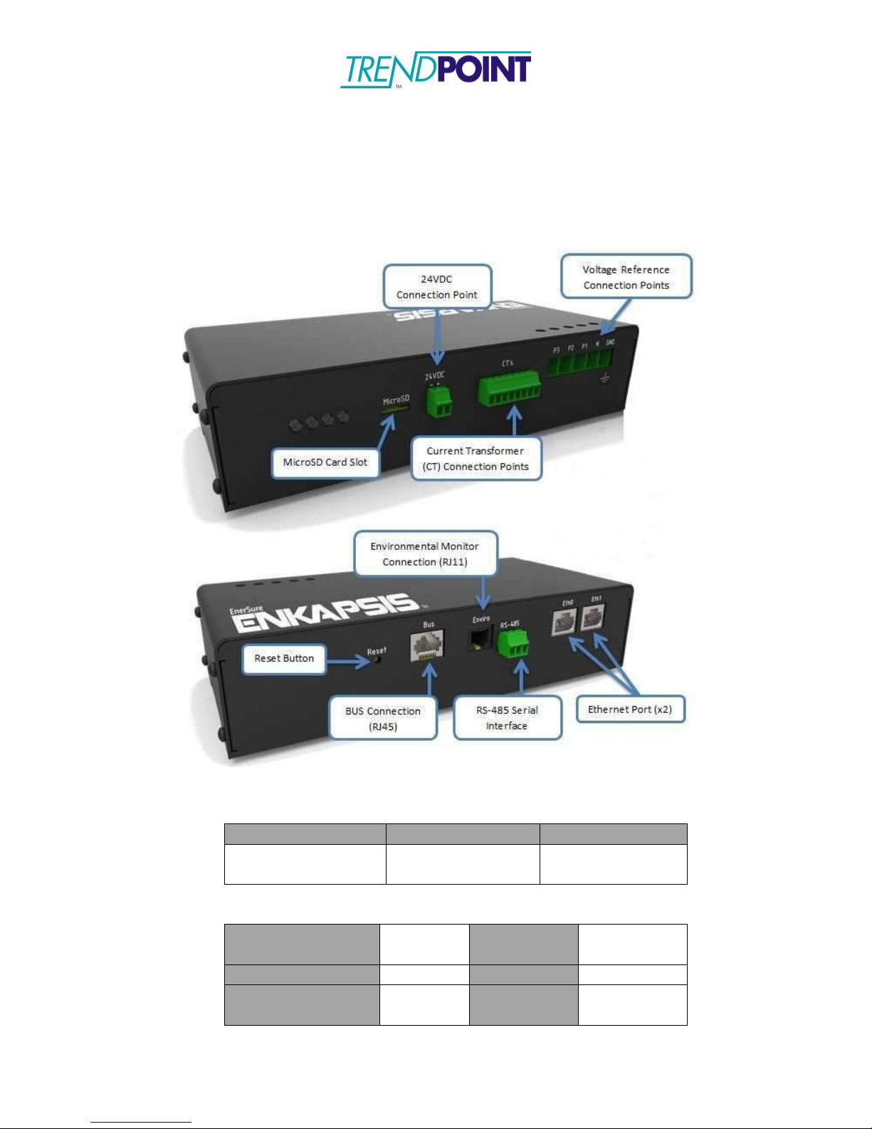
The Enkapsis® PQM Overview
The Enkapsis PQM system is comprised of the PQM, Current Transformers (CT),
and the Power Supply. The EnerSure provides true RMS data for Volts, Amps,
Power Factor, Watts, kWh, kVAR, kVARh, Hz, vTHD and iTHD.
Figure 1: Enkapsis PQM
Electrical Properties
Dimensions
Page 6

Enkapsis & EnerSure Platform Installation Guide Rev07.2
6
Component Description
Current Transformers
Each Current Transformer (CT) can be connected to a circuit by opening or
removing the top of the CT and snapping it onto the wire going from the power
source to the load. THE CT LABEL ALWAYS FACES THE POWER SOURCE.
Be sure to close the CT tightly or it will affect the readings your Enkapsis PQM
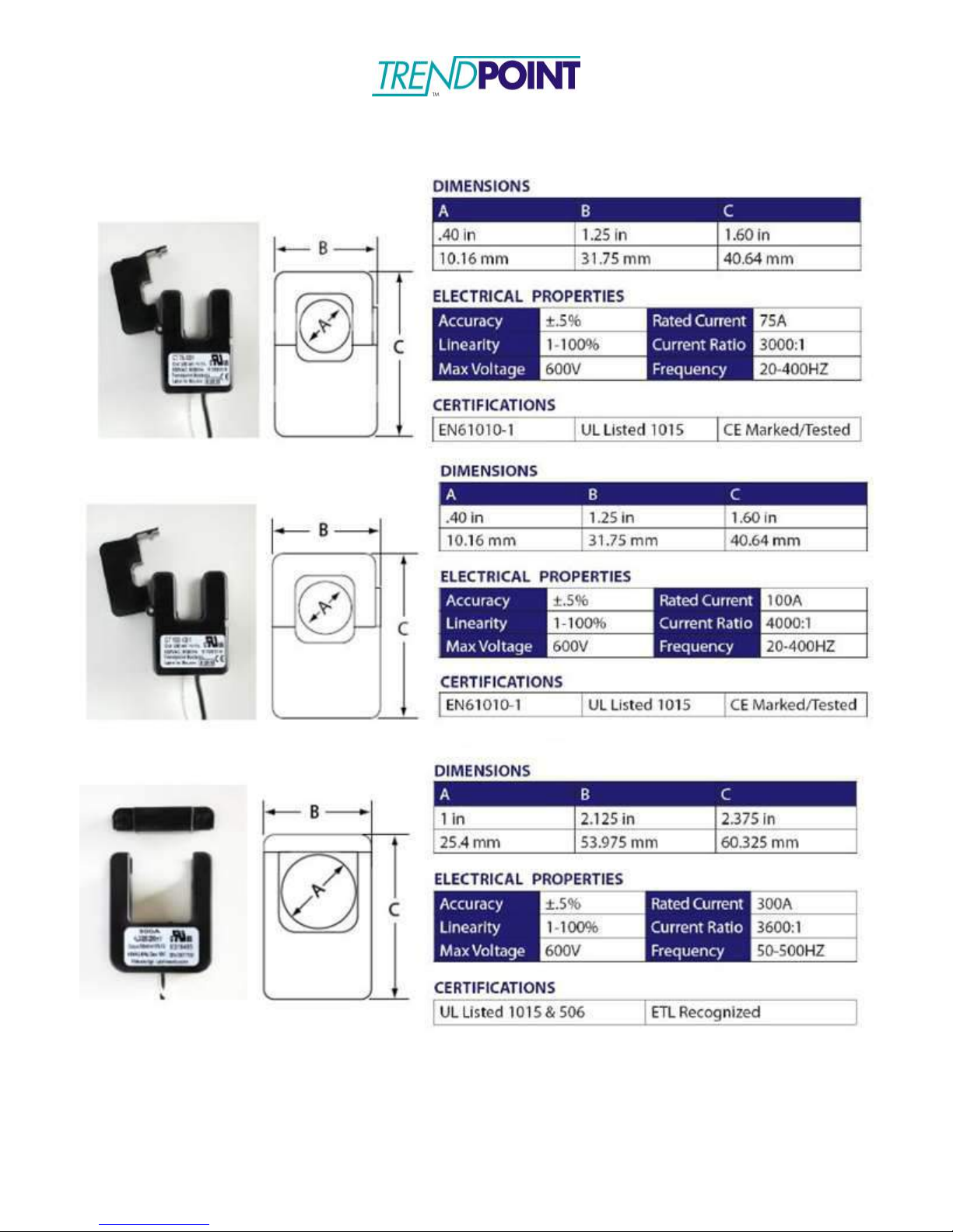
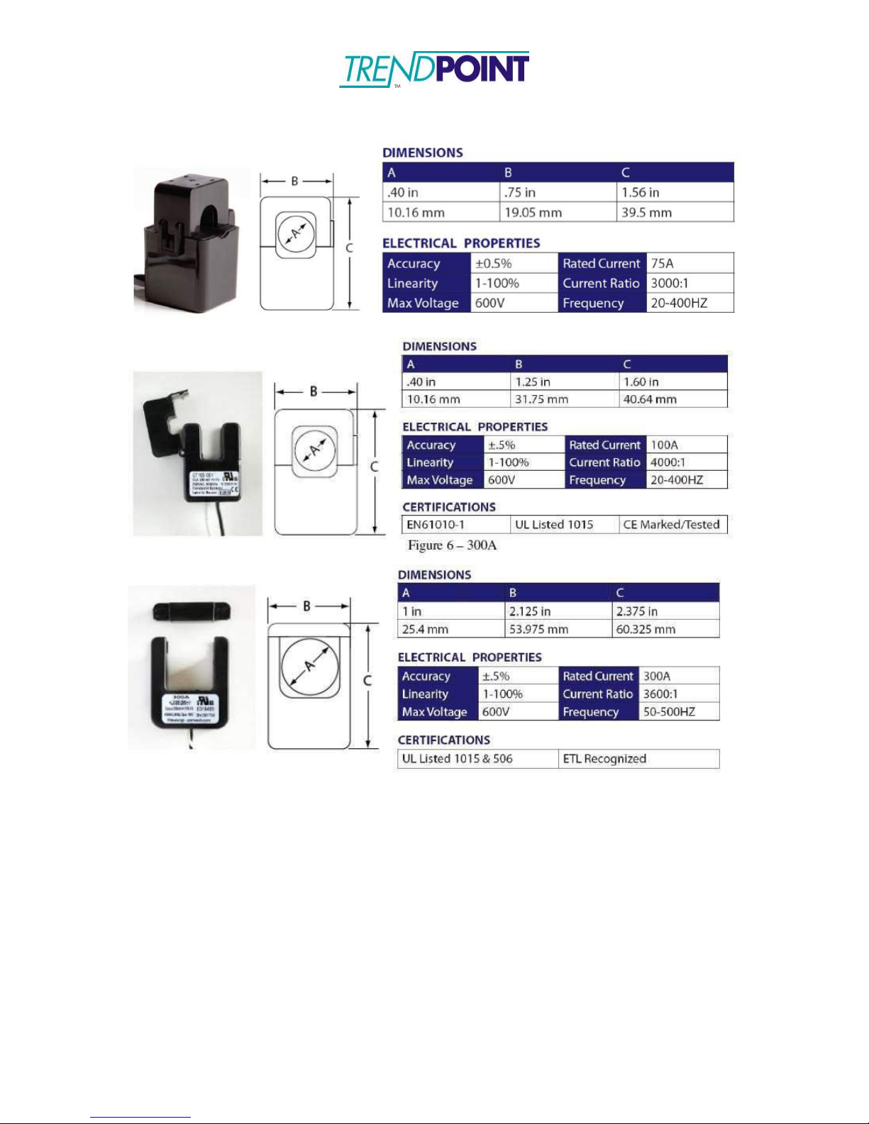
provides. Refer to Figure 2 to reference pictures of our most commonly used
CT’s.
Note: We currently offer a variety of CT’s capable of monitoring
current loads ranging from 0 to 5000 amps.
The CT’s may be simply hung on the wire which they snap around. However,
some customers may prefer to use Velcro strips on the bottom or hinged side of
the unit, to allow for ease of mounting and removal when necessary. Velcro is
non-conductive and should not bring any code issues into play.
The white and black lead wires from each CT are associated with specific ports
on the Enkapsis PQM.
Each CT output has two wires. In North America, ALWAYS CONNECT THE
WHITE WIRE FROM EACH CT TO THE CONNECTOR PORT CLOSEST TO
THE VOLTAGE REFERENCE INPUT AND CONNECT THE BLACK WIRE TO
THE SECOND CT INPUT. ALSO BE SURE TO KEEP THE PAIRED LEAD
WIRES TOGETHER. MIXING LEAD WIRES WILL RESULT IN LOSS OF DATA
AND POSSIBLE DAMAGE TO THE UNITS.
Page 7
Enkapsis & EnerSure Platform Installation Guide Rev07.2
7
Common Current Transformers
Figure 2: Commonly Used CT’s
Page 8
Enkapsis & EnerSure Platform Installation Guide Rev07.2
8
Length
Width
Height
3.31 in
84 mm
1.38 in
35 mm
3.54 in
90.00 mm
Nom. Volts In
100-240V
Volts Out
24VDC ±1%
Max Volts In
85-264V
Amps Out
2.5A
Max Amps In
2A
Pwr Out
60W
Frequency
45-65HZ
EN61010-1, 61000-3-3 , 50082
CE Marked/Tested
UL 508, 1310
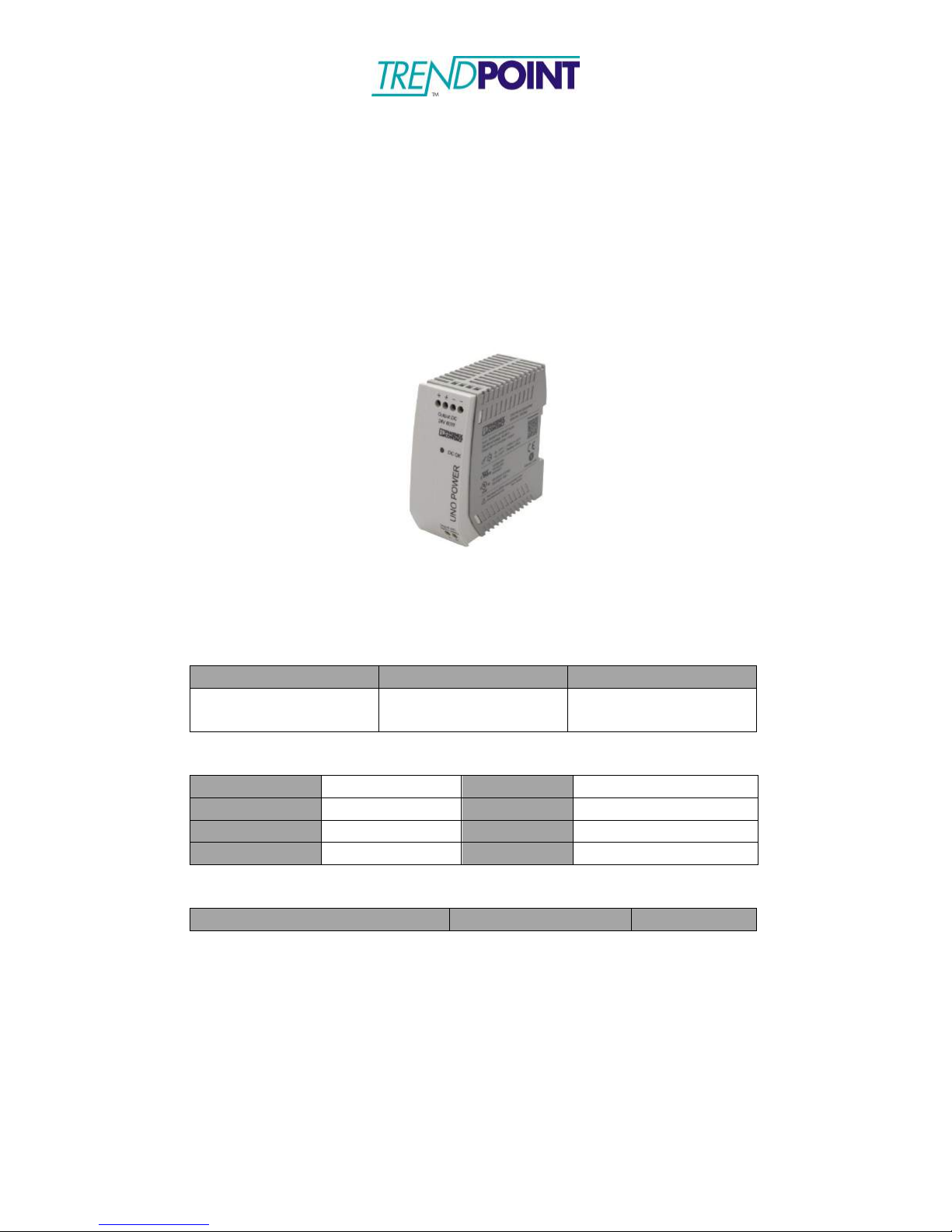
Power Supply
The power supply for the Enkapsis PQM is a Phoenix Contact precision power
supply. This unit requires a 120/240VAC 50 or 60hz input.
The power supply provides 24 volts DC power via one positive and one negative
output terminal. There is no ground output terminal. At 24 volts, the Ekapsis unit
uses approximately 25 mA – 250 mA of power depending on the connected
EnerSure device (BCPM 2.0, iBCPM, Bus, Display).
Figure 3: 24VDC 60W Power Supply
Dimensions
Electrical Properties
Certifications
Page 9
Enkapsis & EnerSure Platform Installation Guide Rev07.2
9
Hardware Installation and Wiring
Electrical Wiring Instructions 3- Phase
Your Enkapsis PQM has 3 separate electrical components that you will need to
connect in order to use the system- Voltage Reference, Power Supply, and
Current Transformers.
All wiring terminals on the Enkapsis PQM can support copper wiring 24-12AWG.
The terminal screws should be tightened to 4.5 lb – inch of torque.
1)
Connect the 24VDC output from the Power Supply to the 2 terminal input
on the Enkapsis.
2)
Connect the 120/208 OR 277/480 VAC input, depending on your system
being monitored, to the Power Supply.
3)
The Enkapsis meter supports the measurement of all of the following
types of voltage (The connection requirements are shown below as well):
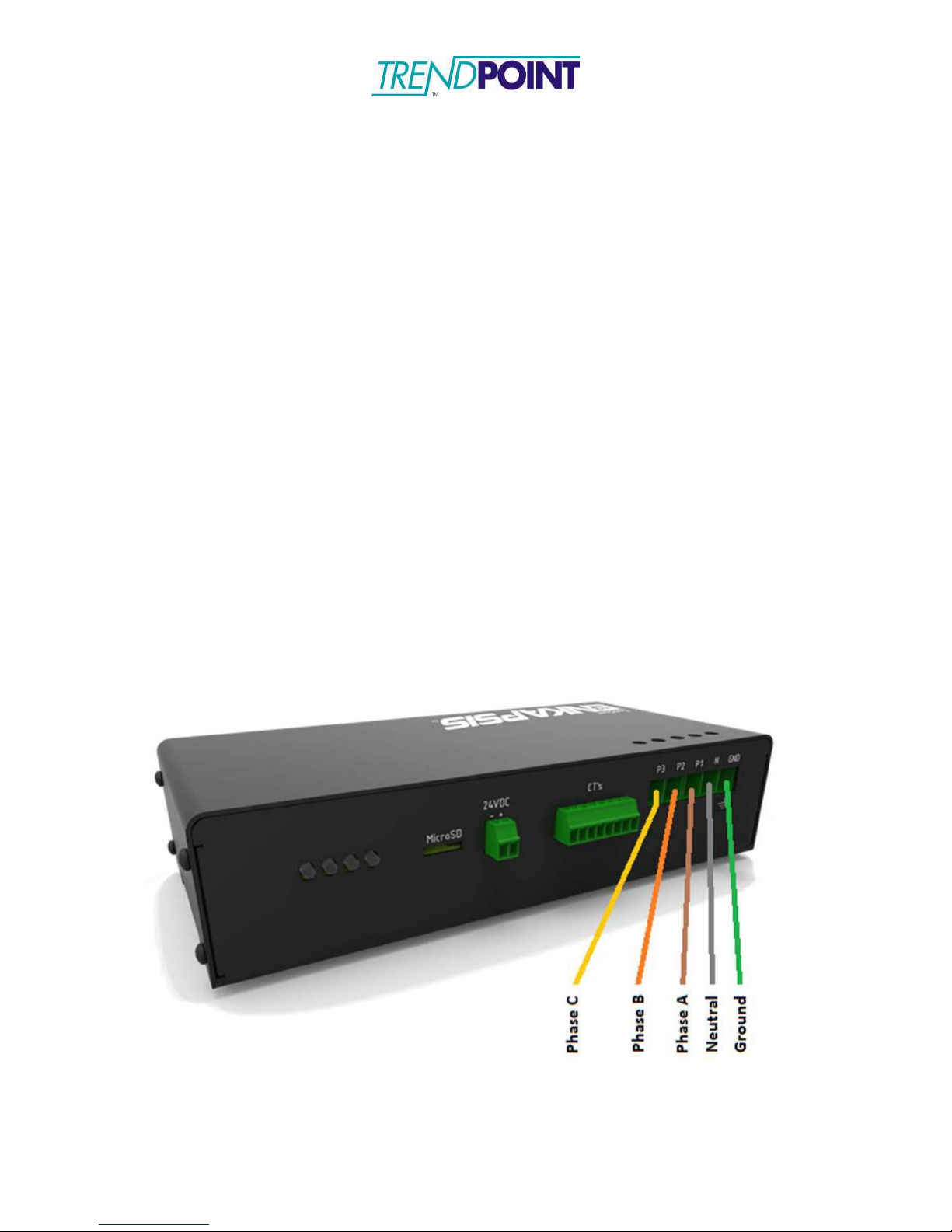
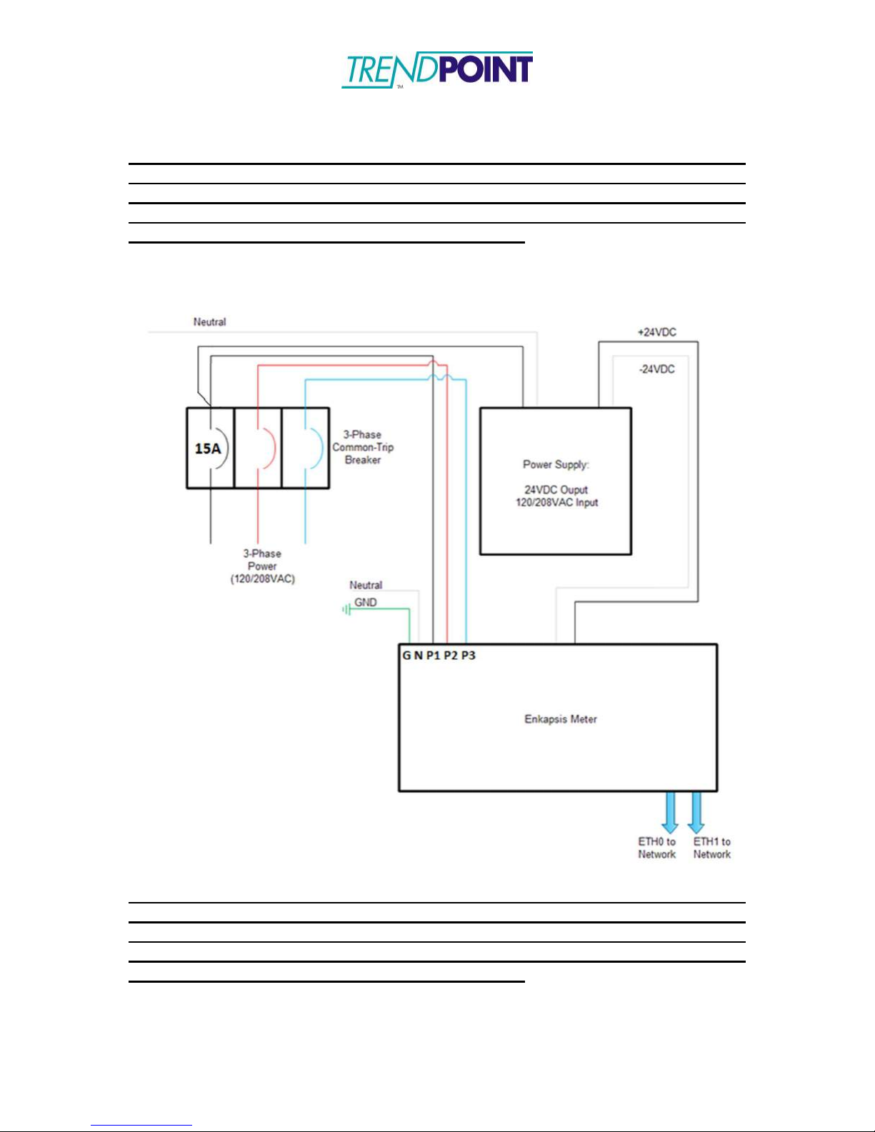
a. Three Phase Wye Power (Also known as 5 wire with Phase A,
Phase B, Phase C, Neutral and Ground - Also See Figure 4 for an
example):
i.
Connect the three phases to a 3-Phase Common-Trip
Breaker of no greater that 15A overcurrent protection located
near the Enkapsis meter (UL listed for Voltages up to 480V
RMS).
ii.
Connect the outputs of the 3-Phase Common-Trip Breaker
to the Voltage Reference connection points on the Enkapsis
meter as shown in the picture below.
Page 10
Enkapsis & EnerSure Platform Installation Guide Rev07.2
10
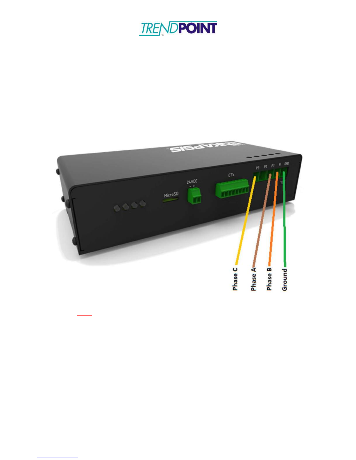
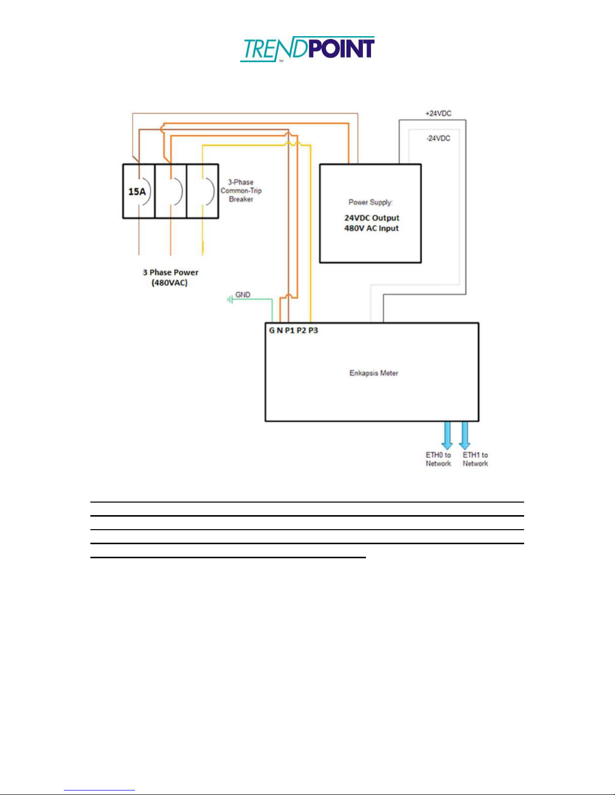
b. Three Phase Delta Power (Also known as 4 wire with Phase A,
Phase B, Phase C, and Ground – Also See Figure 5 for an
example):
i.
Connect the three phases to a 3-Phase Common-Trip
Breaker of no greater that 15A overcurrent protection located
near the Enkapsis meter (UL listed for Voltages up to 480V
RMS).
ii.
Connect the outputs of the 3-Phase Common-Trip Breaker to
the Voltage Reference connection points on the Enkapsis
meter as shown in the picture below. Note that the B Phase
connection is to be connected to the space normally used for
the Neutral Connection for the Wye Three Phase scheme.
*Note: If installing in IT-S power distribution, a 4-conductor disconnect
MUST be used (3-phase + neutral).
4)
Connect the Current Transformers (CT’s).
a.
CT’s should be run from the power panel that is being monitored to
the Enkapsis PQM.
b. The CT’s should be installed with the label facing the source of
power.
c. The wires connected to the Enkapsis PQM terminals should be
installed in a White/ Black configuration, with the white wire of each
CT closest to the Voltage Reference Input, and should be tightened
to 3 lb – inch torque.
d. The CT wires may be cut to length.
5)
Ensure all wiring connections are secure. Once all wiring has been
confirmed energize the Power Supply input.
Page 11
Enkapsis & EnerSure Platform Installation Guide Rev07.2
11
THE GROUND CONNECTION TO THE ENKAPSIS PQM IS MADE DIRECTLY
FROM A STABLE GROUND CONNECTION ON YOUR POWER PANEL. THE
GROUND CONNECTION DIRECTLY TO THE ENKAPSIS IS ABSOLUTELY
MANDATORY AND USE WITHOUT THIS GROUND WILL VOID YOUR
WARRANTY AND CREATE A SAFETY HAZZARD.
THE GROUND CONNECTION TO THE ENKAPSIS PQM IS MADE DIRECTLY
FROM A STABLE GROUND CONNECTION ON YOUR POWER PANEL. THE
GROUND CONNECTION DIRECTLY TO THE ENKAPSIS IS ABSOLUTELY
MANDATORY AND USE WITHOUT THIS GROUND WILL VOID YOUR
WARRANTY AND CREATE A SAFETY HAZZARD.
Figure 4: Wiring Diagram for 120/208VAC Three Phase Wye Configuration
Page 12
Enkapsis & EnerSure Platform Installation Guide Rev07.2
12
THE GROUND CONNECTION TO THE ENKAPSIS PQM IS MADE DIRECTLY
FROM A STABLE GROUND CONNECTION ON YOUR POWER PANEL. THE
GROUND CONNECTION DIRECTLY TO THE ENKAPSIS IS ABSOLUTELY
MANDATORY AND USE WITHOUT THIS GROUND WILL VOID YOUR
WARRANTY AND CREATE A SAFETY HAZZARD.
Figure 5: Wiring Diagram for 480VAC Three Phase Delta Configuration
Page 13
Enkapsis & EnerSure Platform Installation Guide Rev07.2
13
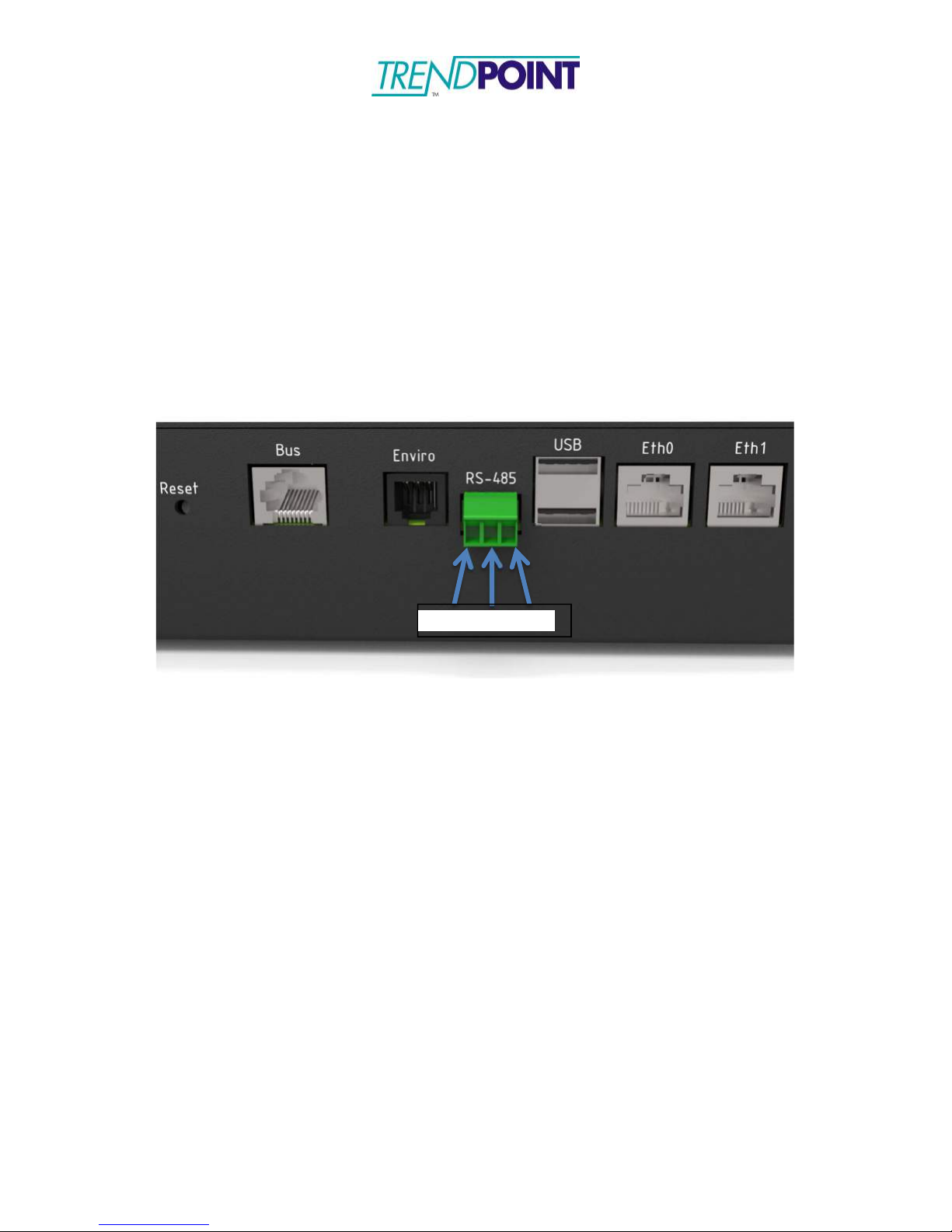
D+ D- GND
RS-485 Wiring
The Enkapsis PQM supports RS-485 Modbus RTU communications. To facilitate
RS-485 communications the following connections should be made. The
EnerSure device can support a multi-drop network on RS-485 2 wire.
1)
Connect the communications wire to the 3- pin terminal block.
D+ / D- / GND
Figure 6: RS-485 Wiring
Page 14
Enkapsis & EnerSure Platform Installation Guide Rev07.2
14
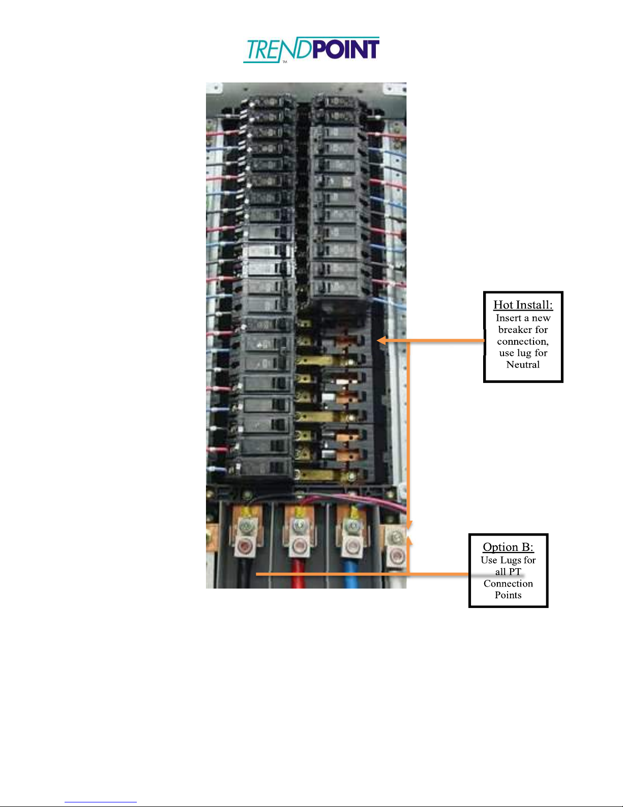
Figure 7: Connection Points for Voltage Reference
Page 15

Enkapsis & EnerSure Platform Installation Guide Rev07.2
15
Figure 8: Close-up of CT Connection Points (300A CT Shown)
Page 16
Enkapsis & EnerSure Platform Installation Guide Rev07.2
16
EnerSure BCPM 2.0
Overview
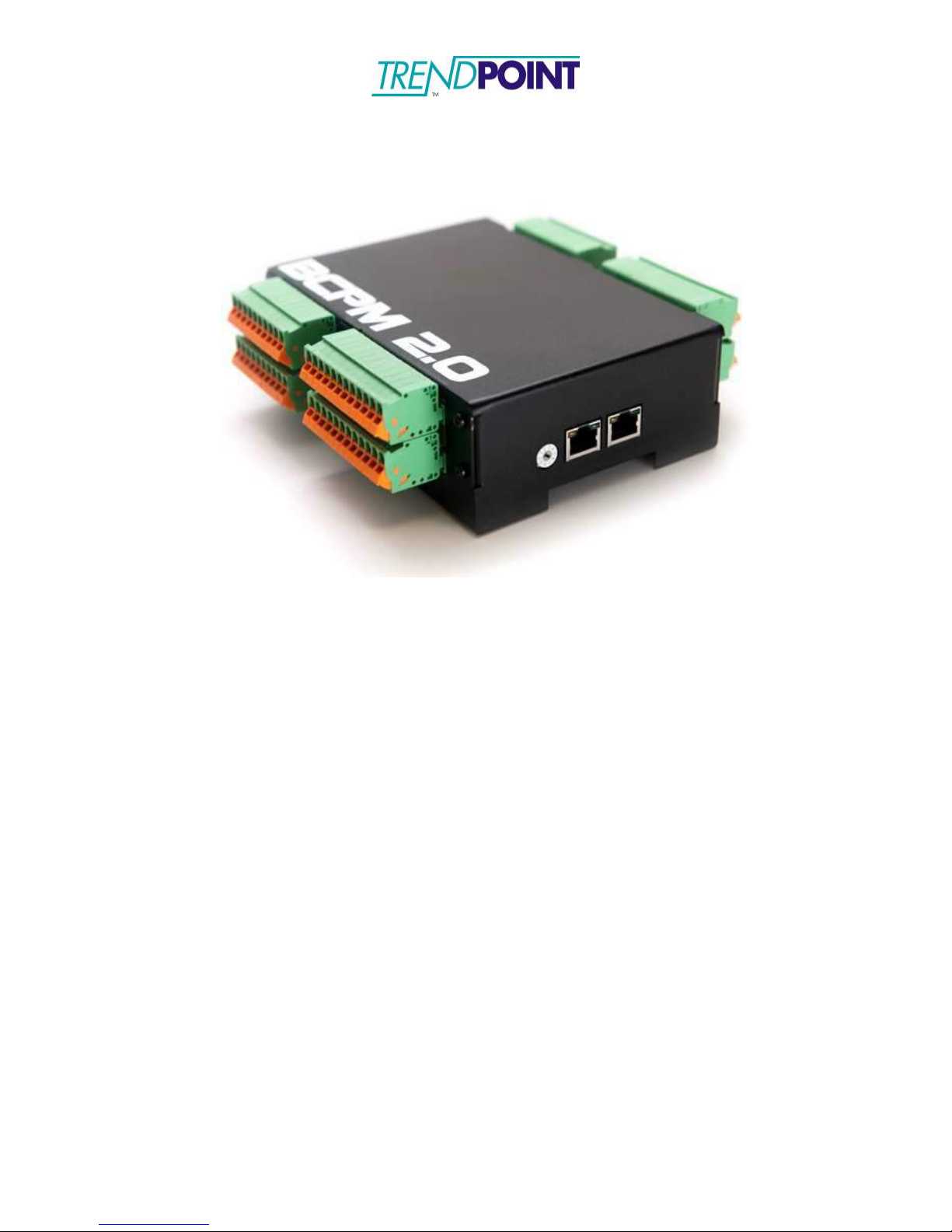
The EnerSure BCPM 2.0 system consists of three (3) main components:
1.) Enkapsis PQM
2.) EnerSure BCPM 2.0
3.) Current Transformers
a.
Installed in the enclosure for the Enkapsis and connected to Enkapsis via a
straight-through CAT5/CAT6 cable.
b.
Comes in 2 sizes: a 24 circuit and 42 circuit modules. Two 42
circuit modules can be combined into a single housing to produce a
84 circuit module.
a.
The CTs provided with the system are split core and are attached to the
circuit after a wire has been connected to the breaker.
b.
Standard CT’s come with 12ft leads which can be cut to properly fit the
installation.
Page 17
Enkapsis & EnerSure Platform Installation Guide Rev07.2
17
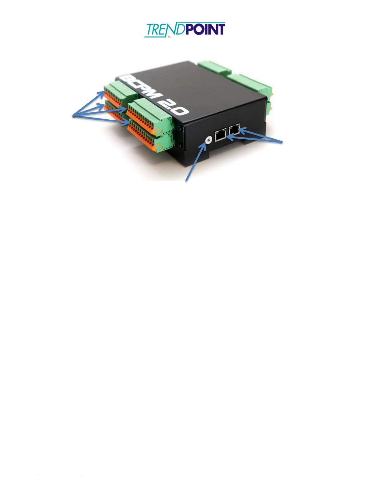
CT Connectors
BCPM 2.0
The BCPM 2.0 should be mounted inside an enclosure or panel in close proximity to the
Enkapsis unit. The BCPM 2.0 received its power, voltage reference, and communications
via a straight-through CAT5/CAT6 cable that is connected to one of the BCPM 2.0’s RJ45 connectors and the BUS port on the Enkapsis.
Note: Multiple BCPM 2.0s can be daisy chained together, via RJ-45 connectors, to allow
monitoring of up to 120 circuits.
RJ-45 Connectors
Addressing Switch
Current Transformers
Each Current Transformer (CT) can be connected to a circuit by opening or
removing the top of the CT and snapping it onto the wire going from the power
source to the load. THE CT LABEL ALWAYS* FACES THE POWER SOURCE.
Be sure to close the CT tightly or it will affect the readings your EnerSure unit
provides. Refer to Figures 5 and 6 to reference pictures of our most commonly
used CT’s.
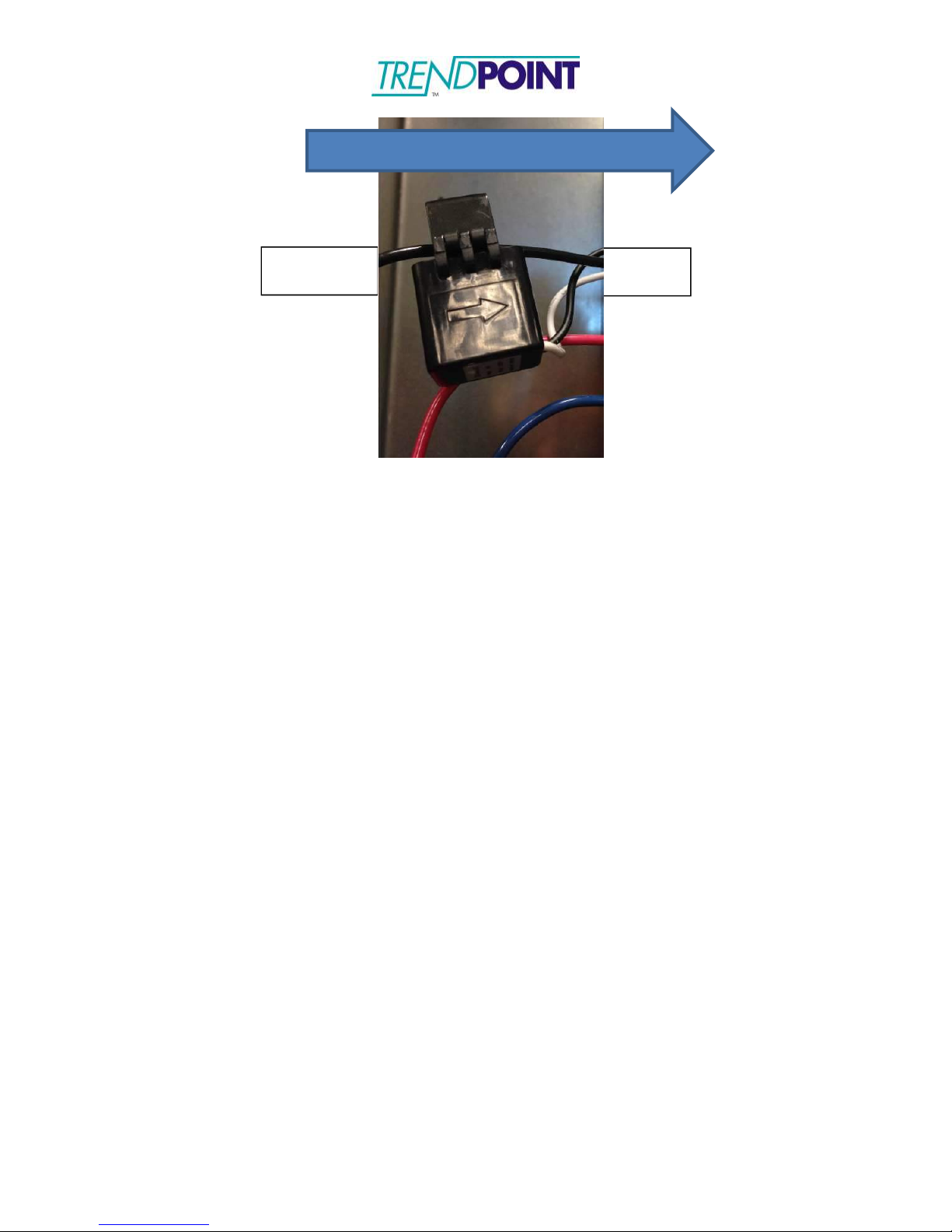
*Note: We currently offer a variety of CT’s capable of monitoring current
loads ranging from 0 to 5000 amps. Specific 75A CT’s, marked with an
arrow, should be oriented using the directional arrow, not the label, see
below figure.
Page 18
Enkapsis & EnerSure Platform Installation Guide Rev07.2
18
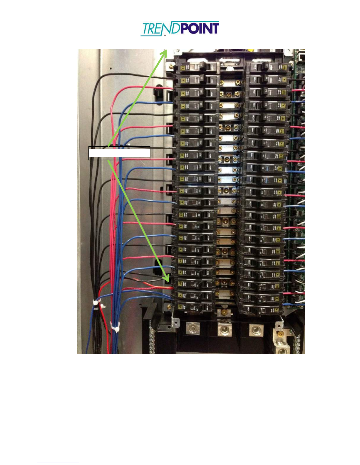
Breaker Panel Circuit Number
BCPM 2.0 Connector Level
BCPM 2.0 Connector Position
1-22
1 (Bottom)
1-22
23-44
2 1-22
45-66
3 1-22
67-84
4 (Top)
1-18
Current Flow
Breaker
Load
The CT’s may be simply hung on the wire which they snap around. However,
some customers may prefer to use Velcro strips on the bottom or hinged side of
the unit, to allow for ease of mounting and removal when necessary. Velcro is
non-conductive and should not bring any code issues into play.
The white and black lead wires from each CT are associated with specific ports
on the BCPM 2.0. Note that the numbered positions on your breaker panel will
correspond to the numbered positions on your BCPM 2.0 as follows:
Each CT output has two wires. In North America, ALWAYS CONNECT THE
WHITE WIRE FROM EACH CT TO THE CONNECTOR PORT CLOSEST TO
THE RJ-45 CONNECTOR AND CONNECT THE BLACK WIRE TO THE
SECOND CT INPUT. ALSO, BE SURE TO KEEP THE PAIRED LEAD WIRES
TOGETHER. MIXING LEAD WIRES WILL RESULT IN LOSS OF DATA AND
POSSIBLE DAMAGE TO THE UNITS.
An example of connecting the CT’s would be connecting circuit number 1 on your
breaker panel to the bottom connector, terminal 1. Circuit number 23 is
connected to the second level connector, terminal 1. Circuit number 84 is
connected to the top connector, terminal 18. The odd numbered circuits on the
BCPM 2.0 are located on the left hand side of the board just as the odd
numbered circuits on the power panel are located on the left-hand side and even
numbers circuits located on the right hand side.
Page 19
Enkapsis & EnerSure Platform Installation Guide Rev07.2
19
Common Current Transformers
Page 20
Enkapsis & EnerSure Platform Installation Guide Rev07.2
20
Overview
EnerSure iBCPM
The EnerSure iBCPM system consists of three (3) main components:
1.) Enkapsis PQM
2.) EnerSure iBCPM CT Strips
a.
Installed in the panel that is being monitored by the system. The CT strips
are mounted next to the breakers and are design for panels with ¾”
breaker spacing.
b.
The current transformers plug into the CT strip.
c.
Each CT strip supports 21 current transformers.
3.) Current Transformers
a.
The CTs provided with the system are split core and are attached to the
circuit after the wire has been connected to the breaker.
b.
The standard CT size is 75A and is designed to be fit into panels with ¾”
breaker spacing.
Page 21
Enkapsis & EnerSure Platform Installation Guide Rev07.2
21
Addressing Switch
RJ-45 Connectors
CT Connectors
iBCPM CT Strips
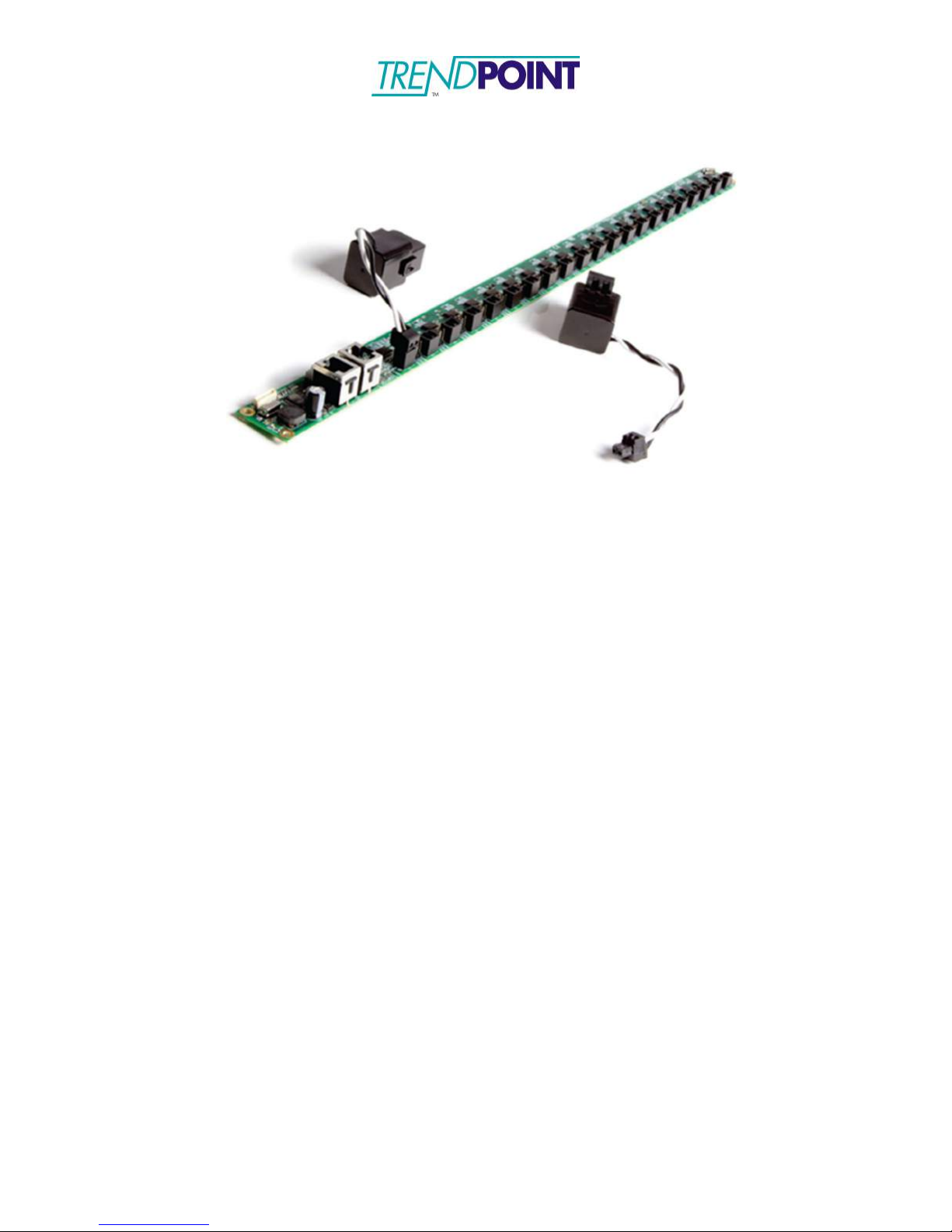
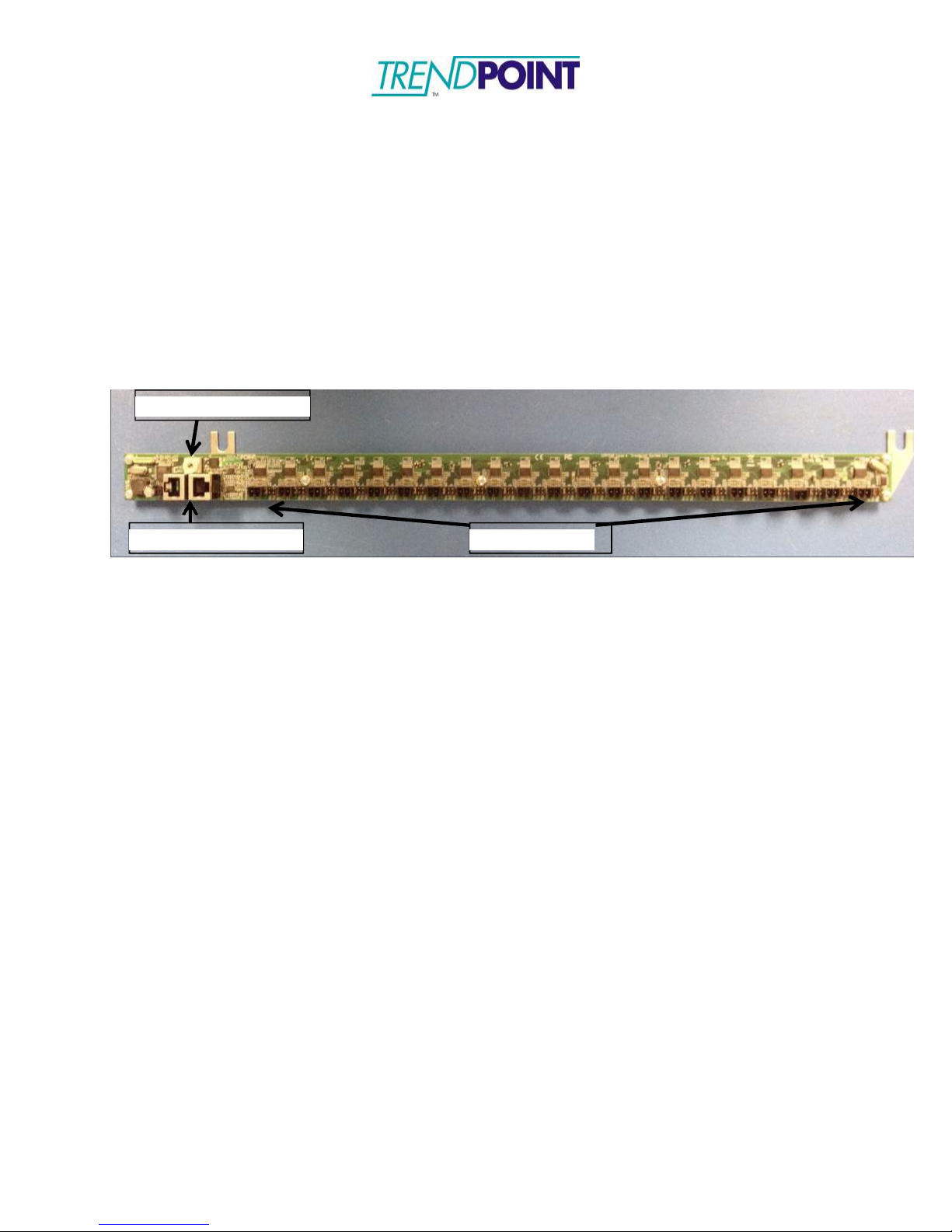
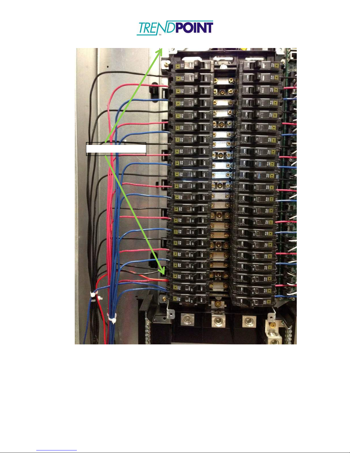
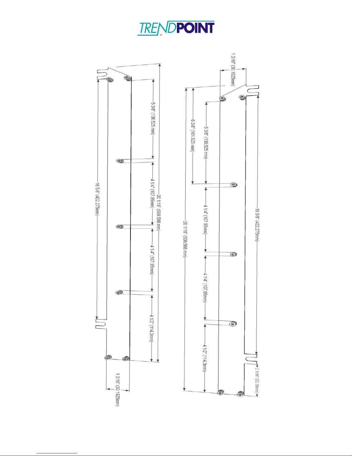
The CT strips are designed to be mounted inside the panel being monitored. The CTs
provided with the system are equipped with 3” leads and a crimp connector to be plugged
into the CT Strip PCB. The CT Strip bracket has been designed to mount next to the
breakers inside the panel. However, mounting locations may be changed to support the
installation.
1.) Loosen the screws on the top and bottom of the panel. Two (2) screws are located
on each side of the panel, totaling four (4) for a standard 42 circuit panel board.
2.) Place the CT Strip mounting bracket under the screw heads and re-tighten the
screws.
Figure 9: iBCPM CT Strip
NOTE: The CT strips can be placed in a top-feed or bottom-feed panel. The RJ-45
connectors can be on the top of the panel or on the bottom to facilitate the
installation. Designation of a top-feed or bottom-feed panel is performed during the
commissioning and setup of the system using the onboard web interface.
Page 22
Enkapsis & EnerSure Platform Installation Guide Rev07.2
22
Mounting Screws
Figure 10: CT Strip Mounting Screws
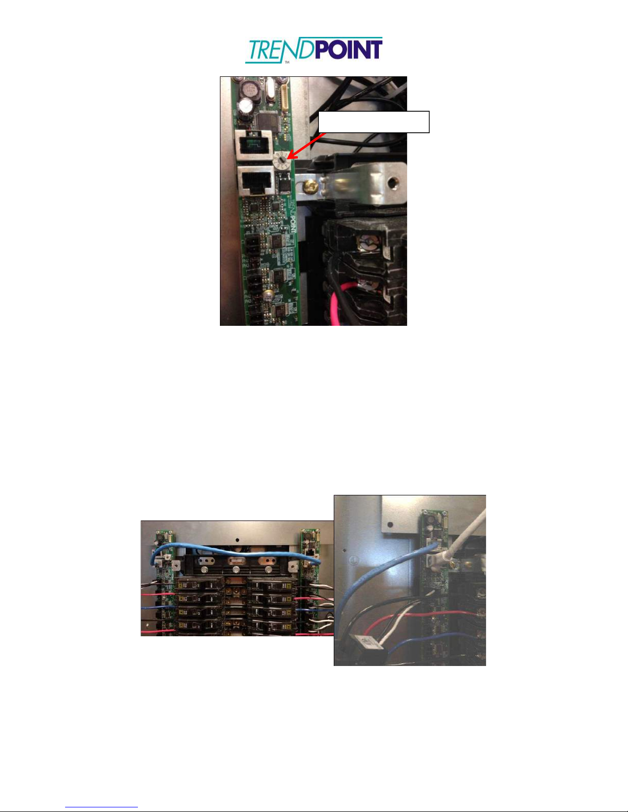
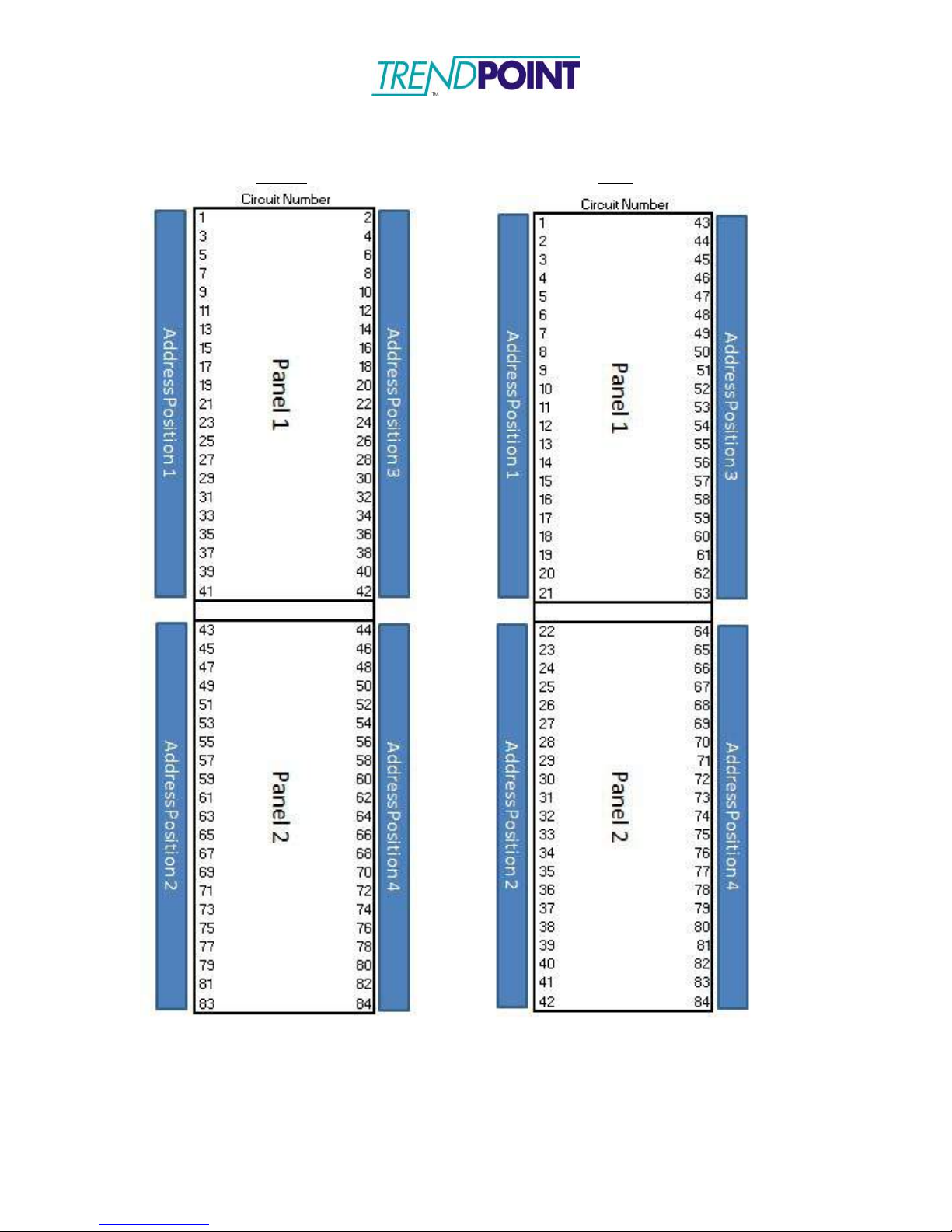
3.) Each CT strip requires an address to be designated.
a. For a standard 42 circuit panel (ANSI) the left CT strip (odd numbered
circuits) should be address position1 and the right CT Strip (even
numbered circuits) should be address position 3. (See CT Strip
Addressing Diagram)
Page 23
Enkapsis & EnerSure Platform Installation Guide Rev07.2
23
Addressing Switch
Figure 11: Addressing Switch
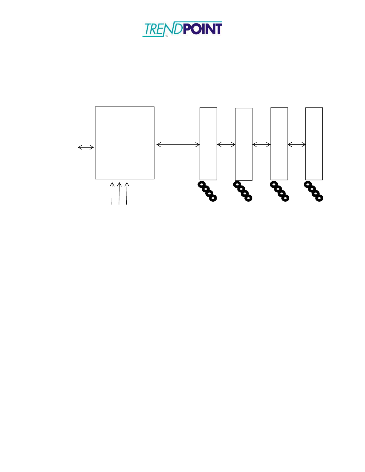
4.) The CT Strips are connected in a daisy-chain format using Ethernet cables (not
provided). The first (or last) CT strip in the daisy-chain is connected to the Bus
port on the Enkapsis.
a.
Standard CAT5 or CAT6 straight-through Ethernet cables are used for the
daisy-chain.
b.
All 8 wires of the daisy-chained Ethernet cables are used to provide
communications, voltage reference, and power for the CT Strips.
NOTE: Straight-through Ethernet cables must be used. Do NOT use a crossover
cable format, this may cause damage to the iBCPM system.
Figure 12: RJ-45 Cable Daisy Chain
Page 24
Enkapsis & EnerSure Platform Installation Guide Rev07.2
24
P2
P1
P3
CT
Setting Strip Jumpers
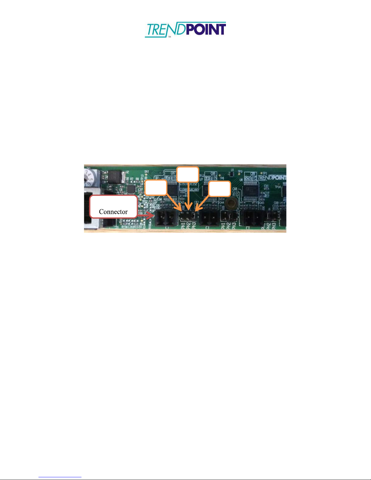
Each iBCPM strip has a series of 21 jumpers that need to be placed correctly in order for
the strips to gather proper data. These jumpers come pre-set for either a top or bottom
fed panel as ordered, but they should be checked to ensure proper setup. Figure 13 shows
a close-up of a jumper and its possible positions. Jumpers should be set to P1 for Phase 1
and Neutral, P2 for Phase 2, and P3 for Phase 3.
Figure 13: Circuit Jumpers (Jumper set to P1 in image)
Page 25
Enkapsis & EnerSure Platform Installation Guide Rev07.2
25
Current Flow
Breaker
Load
Current Transformers
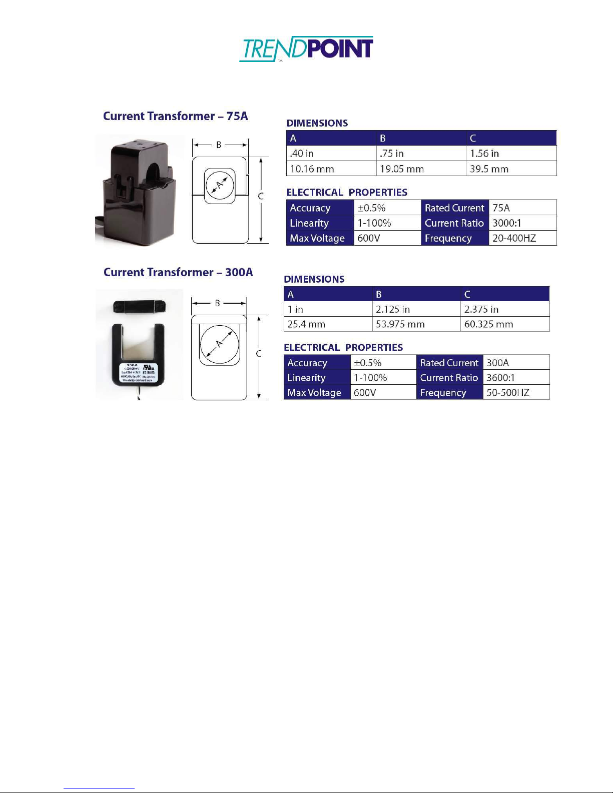
Standard CTs for the iBCPM system are 75A split core CTs with a 3” lead fitted with a
crimp connector. The iBCPM system supports various CT sizes up to 4000A. CTs larger
than 75A are shipped with a screw terminal connector instead of the crimp style
connector that is fitted onto the 75A CT from TrendPoint. The lead lengths on larger CT
sizes can be cut to the desired length and the wires connected to the screw terminals (See
Enclosure Wiring Instructions).
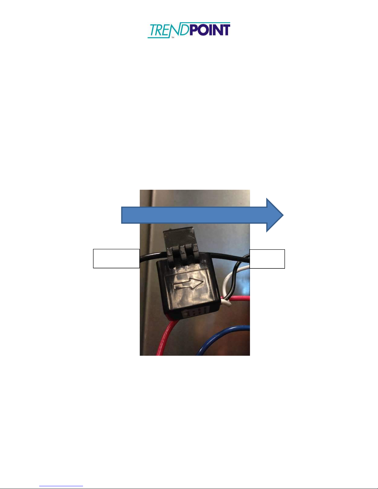
1.) Snap the CT around the line being monitored. Ensure the CT is snapped
completely closed.
a. Each CT is marked with an arrow. The arrow should point along the
direction of the current flow. (Away from the breaker)
2.) Connect the CT to the CT Strip channel corresponding to the circuit. The CT
Strip channels are aligned with each breaker.
Page 26
Enkapsis & EnerSure Platform Installation Guide Rev07.2
26
Common Current Transformer Dimensions
Page 27
Enkapsis & EnerSure Platform Installation Guide Rev07.2
27
iBCPM CT Strip Bracket Dimensions
Page 28
Enkapsis & EnerSure Platform Installation Guide Rev07.2
28
CT Strip Addressing Diagram
ANSI IEC
Page 29
Enkapsis & EnerSure Platform Installation Guide Rev07.2
29
Enkapsis
RJ-45
RJ-45
RJ-45
RJ-45
3 Phase Power
CT
Strip
CT
Strip
CT
Strip
CT
Strip
iBCPM System Block Diagram
Ethernet
CTs - Up to
21 per CT
Strip
Page 30
Enkapsis & EnerSure Platform Installation Guide Rev07.2
30
EnerSure iBCPM2.0
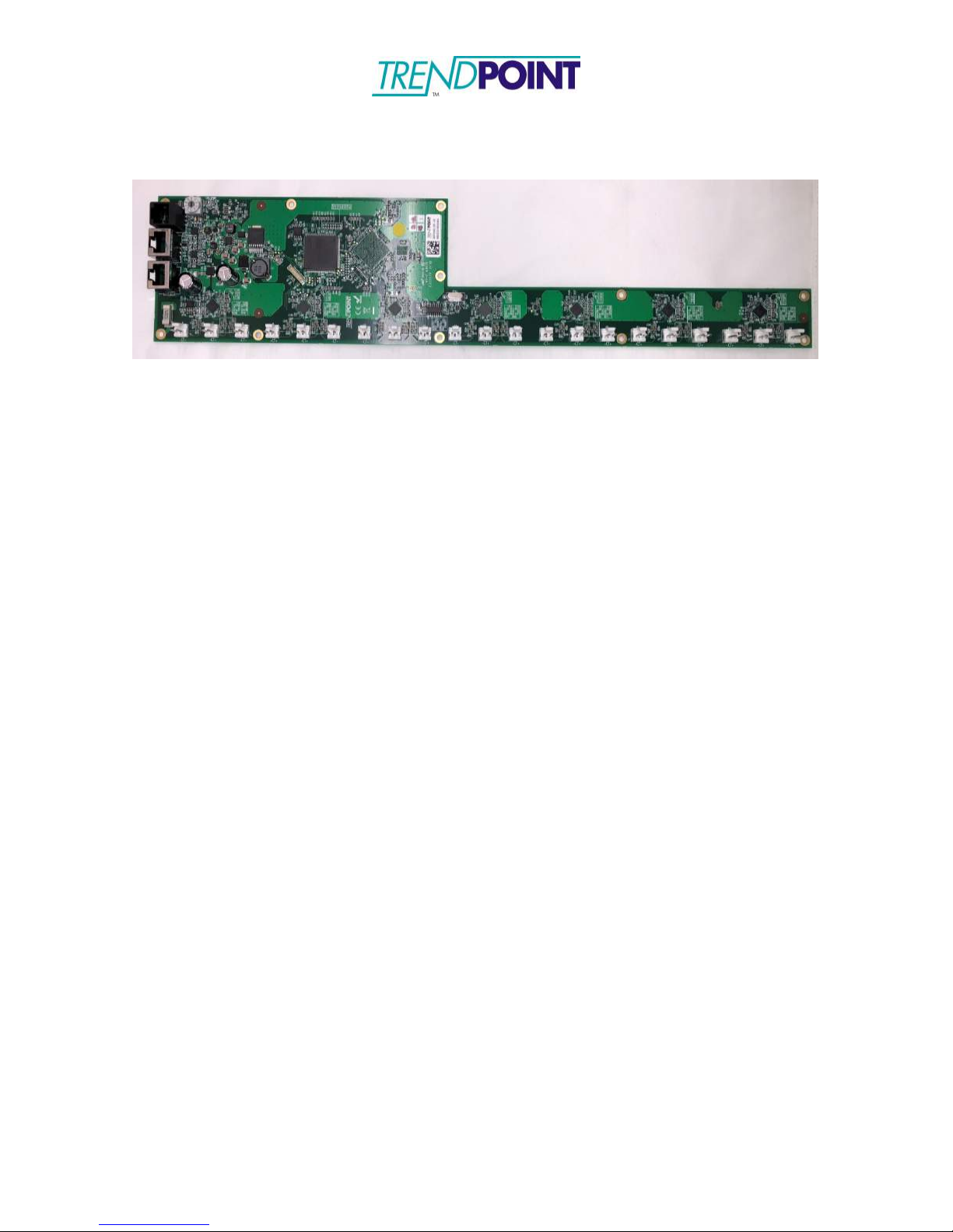
Figure 14: IBCPM 2.0 PCB
iBCPM2.0 Overview
The iBCPM2.0 system consists of three (3) main components:
1.
Enkapsis PQM
2.
iBCPM2.0 PCB
a. Installed in the panel that is being monitored by the system. The IBCPM
2.0 PCBs (Figure 14) are mounted next to the breakers and are design
for panels with ¾” breaker spacing.
b. Each iBCPM 2.0 PCB supports 21 current transformers.
3. TrendPoint Current Tranformers (CTs)
a. The current transformers plug into the iBCPM 2.0 PCB.
Page 31
Enkapsis & EnerSure Platform Installation Guide Rev07.2
31
iBCPM2.0 PCBs
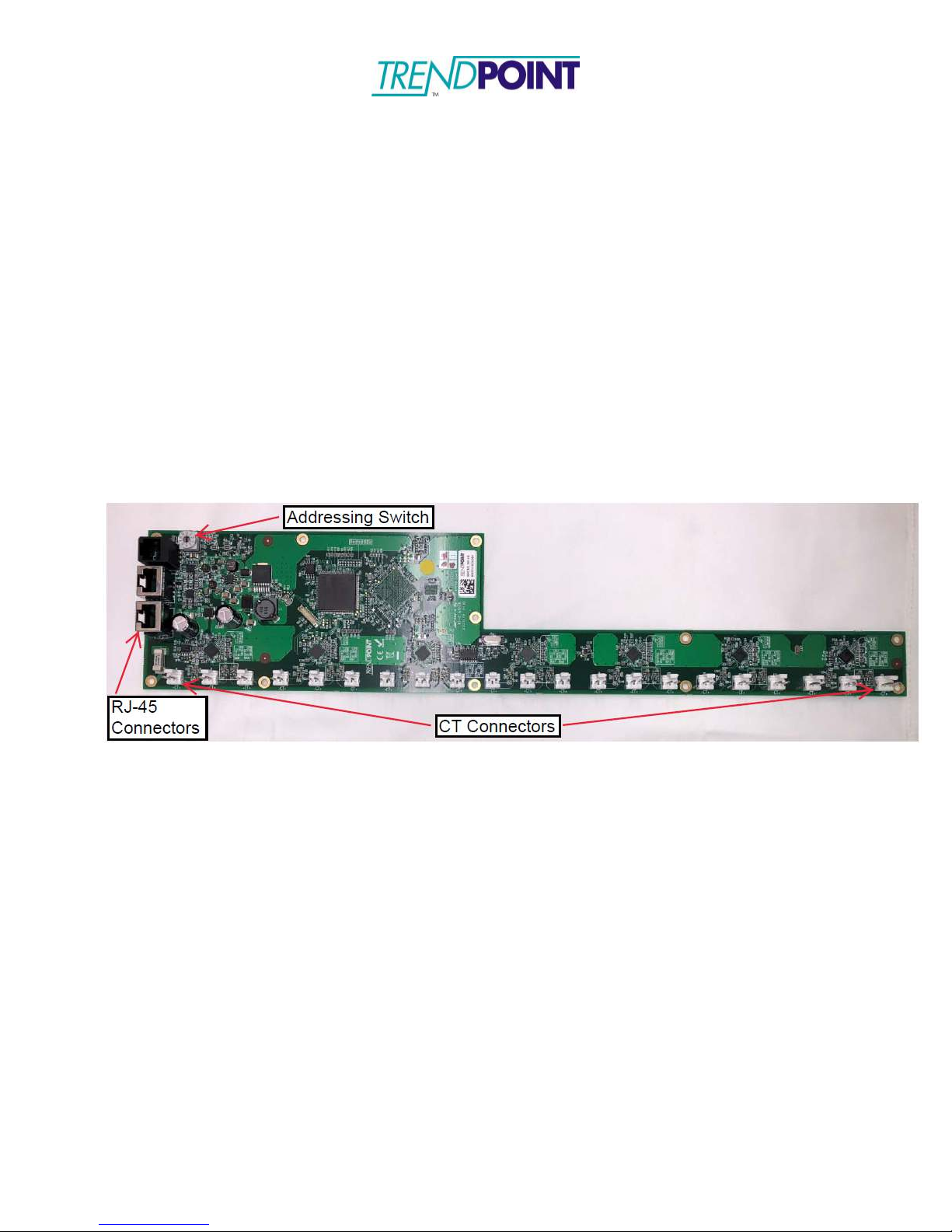
The iBCPM 2.0 PCBs (Figure 15) are designed to be mounted inside the panel being
monitored. The CTs provided with the system are equipped with 4” leads and an Amp
connector to be plugged into the IBCPM PCB PCB. The IBCPM PCB bracket has been
designed to mount next to the breakers inside the panel. However, mounting locations may
be changed to support the installation.
1.) Loosen the screws on the top and bottom of the panel as shown in Figure 16. Two
(2) screws are located on each side of the panel, totaling four (4) for a standard 42
circuit panel board.
2.) Place the iBCPM PCB mounting bracket under the screw heads and re-tighten the
screws.
Figure 15: iBCPM2.0 PCB
NOTE: The iBCPM 2.0 PCBs can be placed in a top-feed or bottom-feed panel. The
RJ-45 connectors can be on the top of the panel or on the bottom to facilitate the
installation. Designation of a top-feed or bottom-feed panel is performed during the
commissioning and setup of the system using the onboard web interface.
Page 32
Enkapsis & EnerSure Platform Installation Guide Rev07.2
32
Mounting Screws
Figure 16: IBCPM PCB Mounting Screws
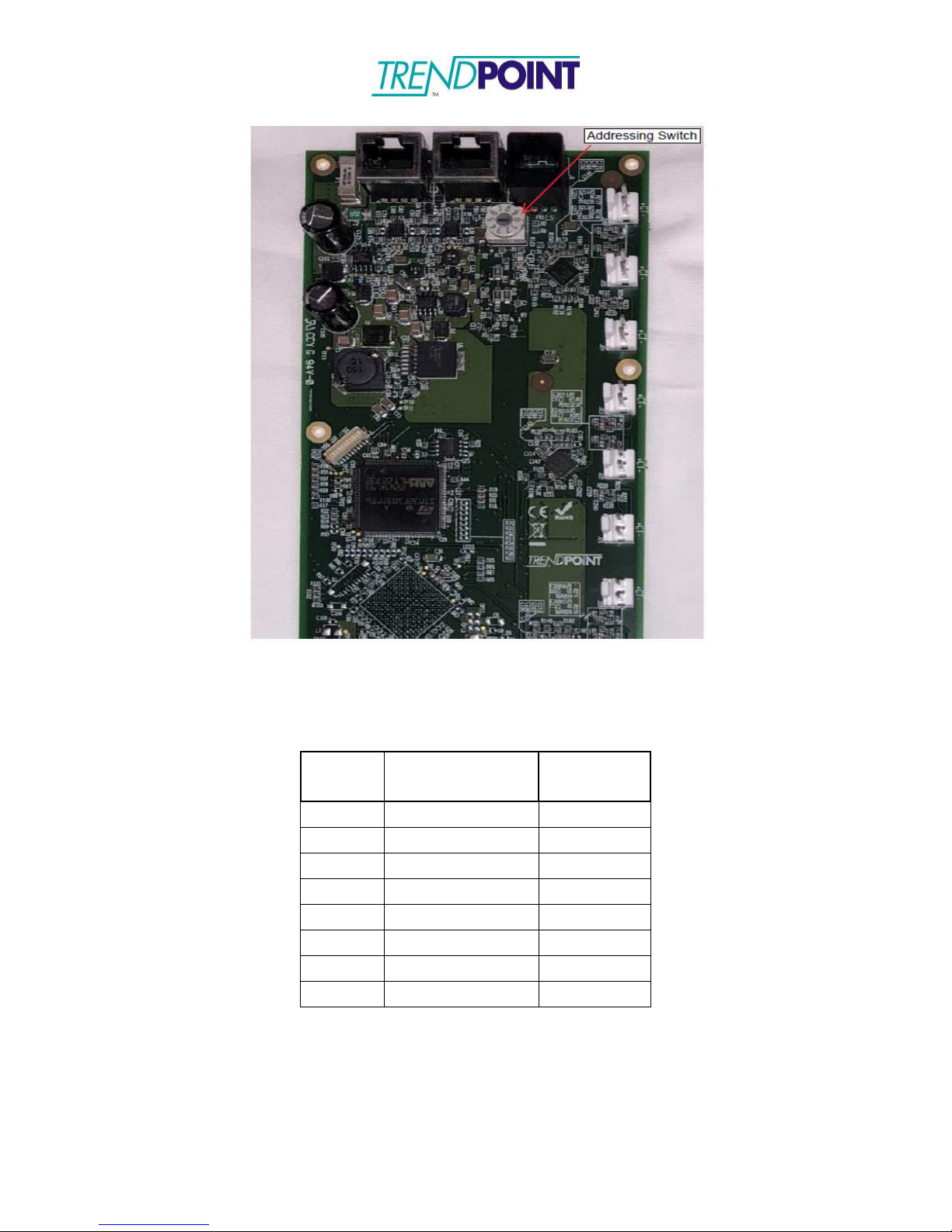
3.) Each iBCPM PCB requires an address to be designated. To address the card, use
the 10 position selector (Figure 17) switches on the IBCPM PCB. The IBCPM
PCB should be set to an address between 1 and 8. The following page, page 33 of this
installation guide contains an Address Matrix to indicate the address selection and the
relation to the circuit numbers.
Page 33
Enkapsis & EnerSure Platform Installation Guide Rev07.2
33
Address
ANSI Circuit
IEC
Circuit
1 1-41 (Odd)
1-21
2 2-42 (Even)
22-42
3 43-83 (Odd)
43-63
4 44-84 (Even)
64-84
5 85-125 (Odd)
85-105
6 86-126 (Even)
106-126
7 127-167 (Odd)
127-147
8 128-168 (Even)
148-168
Figure 17: Addressing Switch
Address Matrix
Page 34

Enkapsis & EnerSure Platform Installation Guide Rev07.2
34
4.) The IBCPM 2.0 PCB are connected in a daisy-chain format (Figure 18) using
standard Ethernet cables (not provided.) The first (or last) IBCPM PCB in the
daisy-chain is connected to the Bus port on the Enkapsis meter.
c.
Standard CAT6 straight-through Ethernet cables are used for the daisychain.
d.
All 8 wires of the daisy-chained Ethernet cables are used to provide
communications, voltage reference, and power for the IBCPM 2.0
PCB.
CAUTION:
CAT6
Straight-through Ethernet cables must be used. Do NOT
use a crossover cable format, this may cause damage to the iBCPM2.0 system.
Figure 18: RJ-45 Cable Daisy Chain
Page 35
Enkapsis & EnerSure Platform Installation Guide Rev07.2
35
Setting Phase Selector
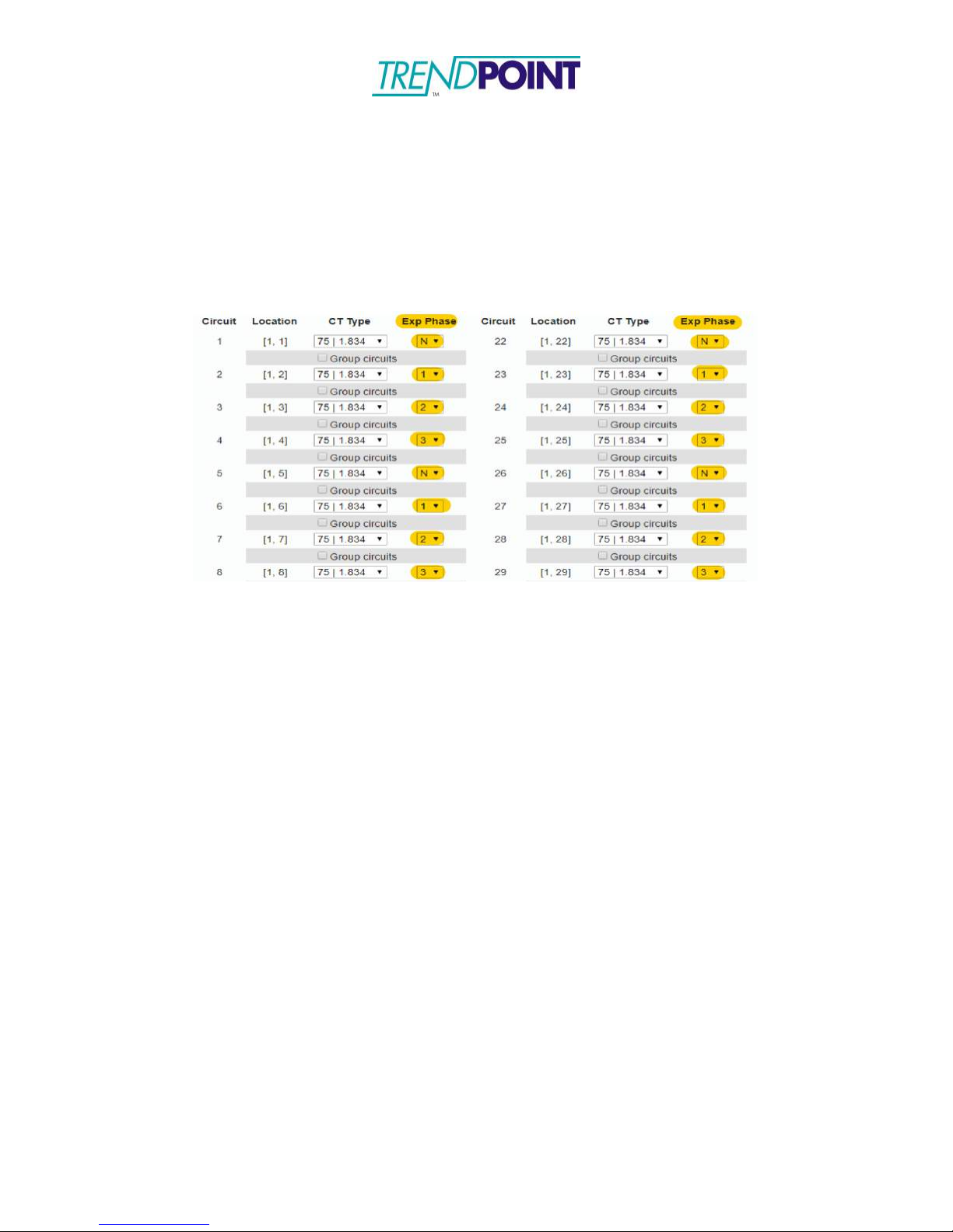
Each iBCPM2.0 strip has a series of Exp Phase’s. Login to the Enkapsis Web-Interface
(under the “
of the CT’s installed. By setting the “Exp Phase” settings this need to be placed correctly
in order for the cards to gather proper data. (Figure 19) shows a screen shot of the Exp
Phase settings in the Web Interface.
Circuit Cfg” tab)
and select the proper phasing that matches the placement
Figure 19:
Circuit Cfg for iBCPM2.0
(Exp Phase Select in image)
Page 36
Enkapsis & EnerSure Platform Installation Guide Rev07.2
36
Current Transformer Installation
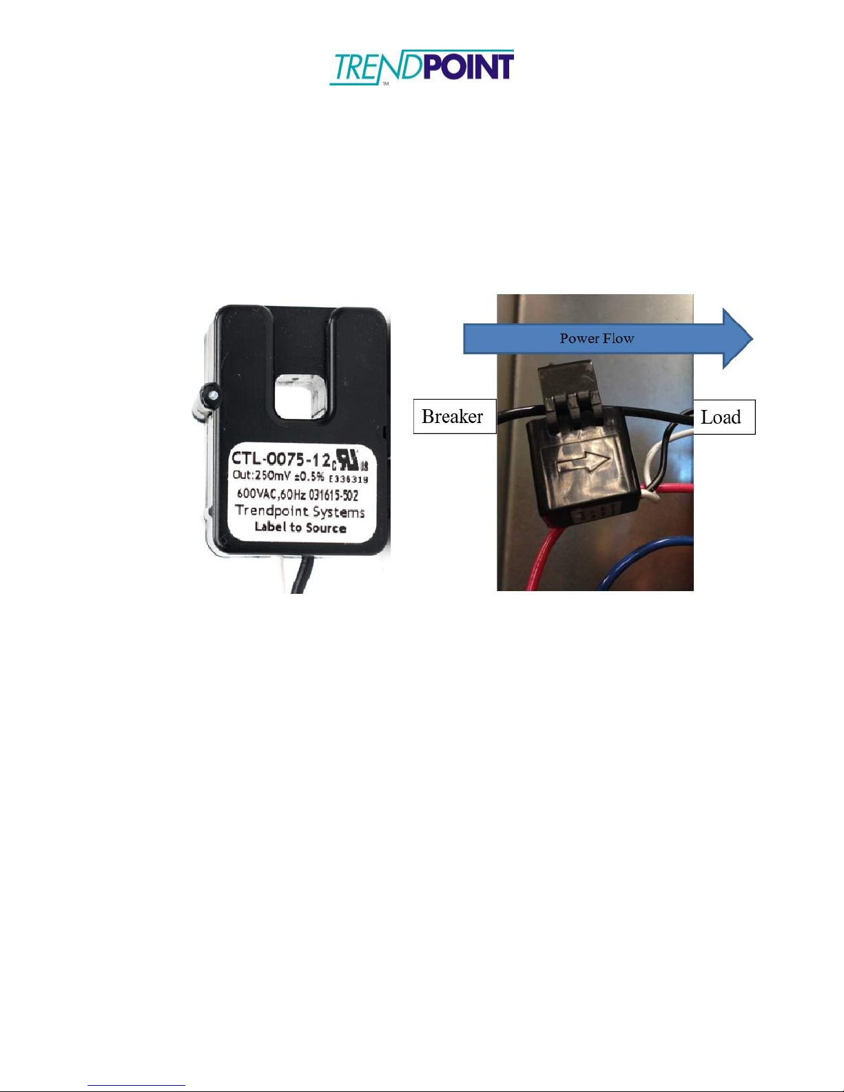
The process of installation is as follows:
1.) Identify the arrow molded on the exterior of the CT or the label that says
“Label to Source”.
Figure 20: CT Orientation Marking
2.) Align the CT (Figure 20) such that the arrow is pointing in the direction of
power flow; pointing away from power source (circuit breaker) towards
load. If the CT does not have an arrow, it will have a label. The label
needs to face the power source.
Caution: Incorrectly aligned CTs may cause incorrect readings and
damage to equipment.
3.) If using a split core CT, close the CT around the line being monitored.
Ensure the CT is snapped completely closed.
4.) Connect the CT lead to the corresponding circuit on the iBCPM 2.0 PCB.
Page 37
Enkapsis & EnerSure Platform Installation Guide Rev07.2
37
EnerSure Bus
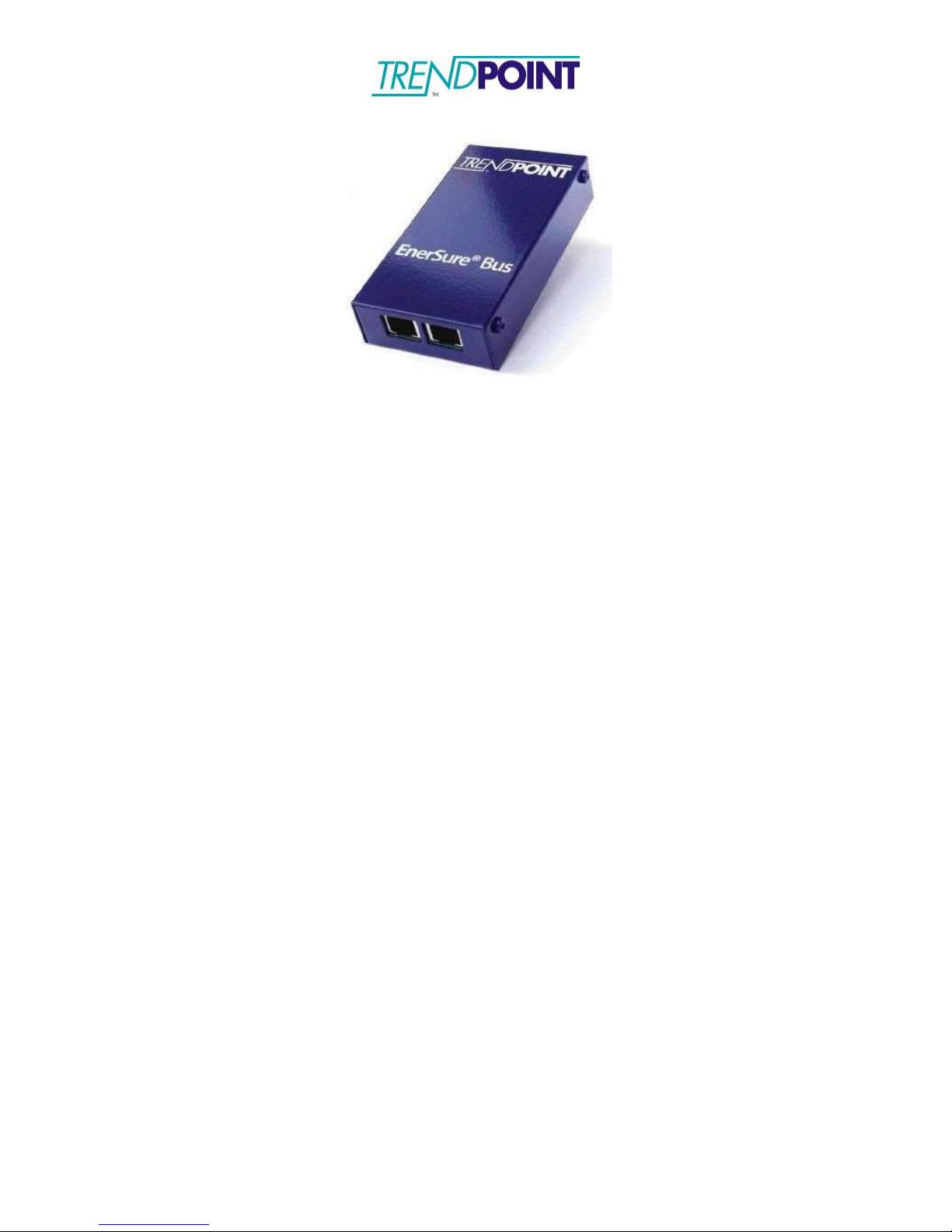
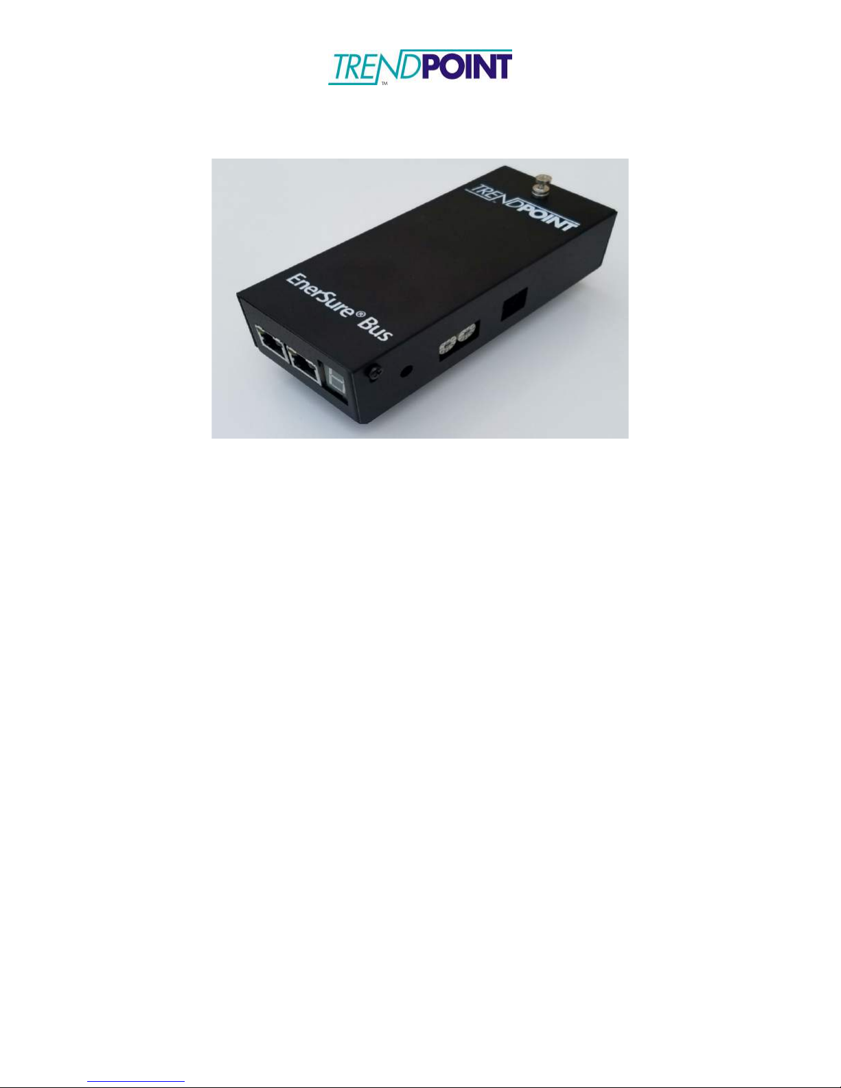
EnerSure Bus Overview
The Installation of the EnerSure bus system involves 3 separate components.
1.) Enkapsis PQM – This unit is mounted inside a Tap Can for the Busway system that
is being fitted with the EnerSure Bus product.
2.) EnerSure Bus Tap Cards - The Bus Tap Cards are mounted on each tap box and
connected in a “daisy-chain” format leading back to the Base Unit. Each Bus Tap
card can support a maximum of 4, or 8, CT’s.
3.) Current Transformers - The current transformers are placed inside of each tap box.
The CT’s are split-core type and are designed to easily snap around the feeds
providing power. The standard CT’s are 75A, but the system can support CT’s up
to 4000A.
*Note: This manual shows how to install and configure TrendPoint’s 4-Circuit Busway
product. TrendPoint also offers an 8-Circuit Busway product that installs and
configures in the same manner.
Page 38
Enkapsis & EnerSure Platform Installation Guide Rev07.2
38
Current Flow
Breaker
Load
Current Transformers
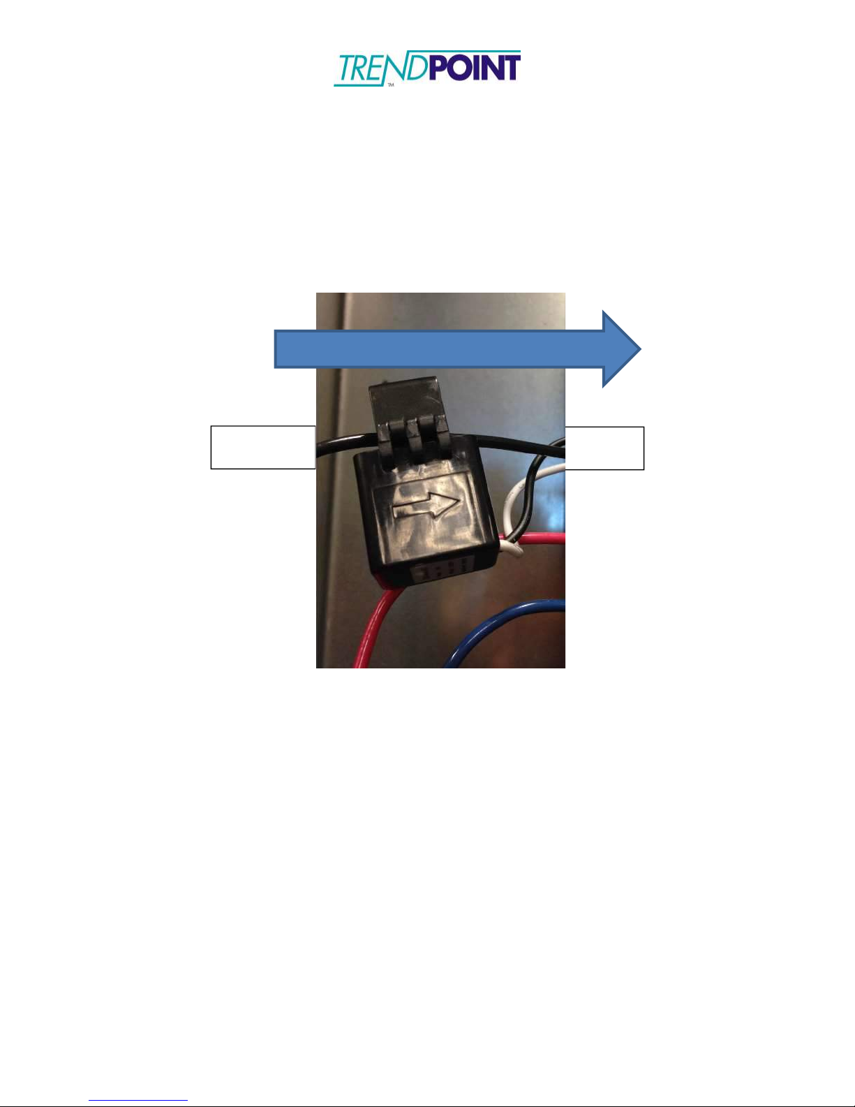
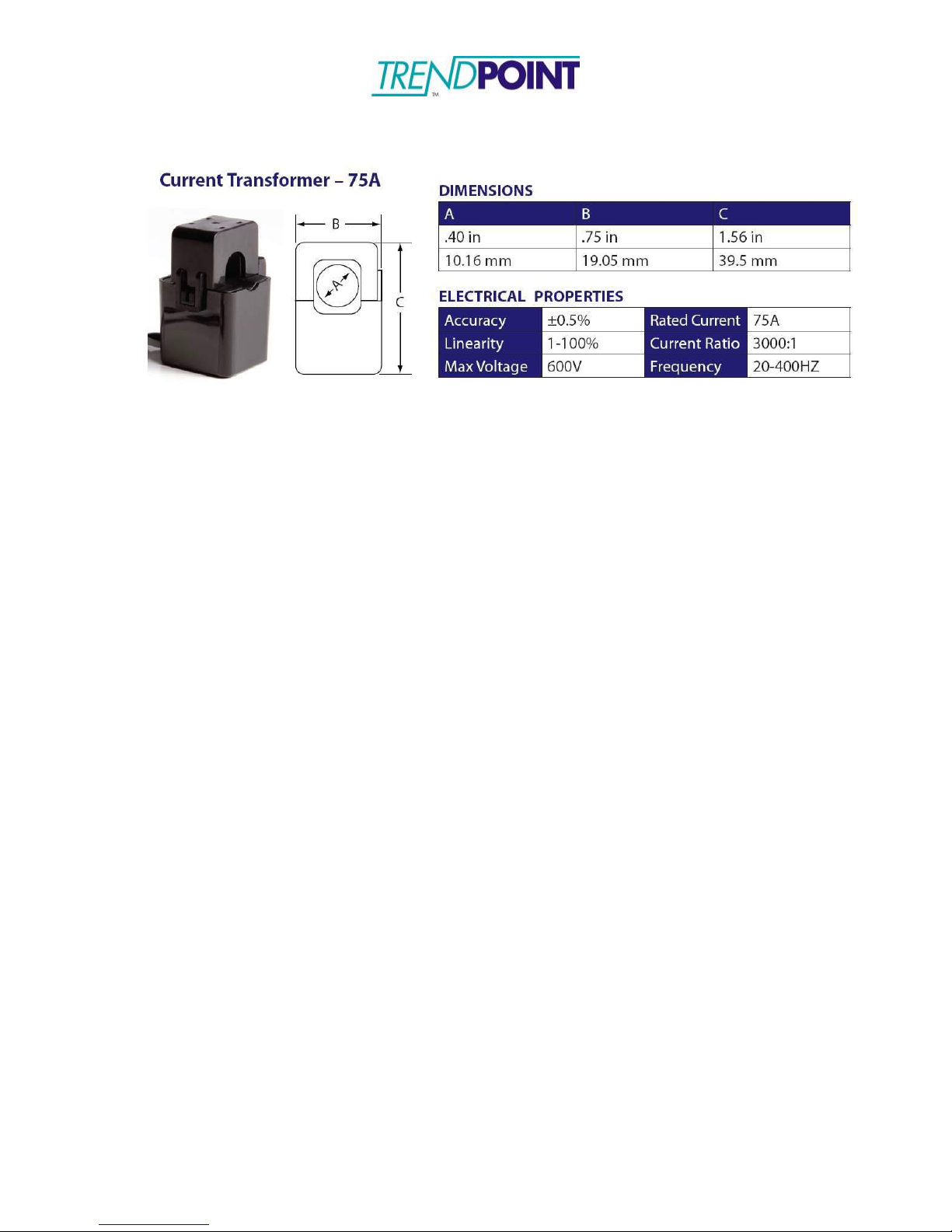
Standard CTs for the EnerSure Bus system are 75A split core CTs. The lead lengths on
the CTs can be cut to the desired length and the wires connected to the screw terminals.
1.) Snap the CT around the line being monitored. Ensure the CT is snapped
completely closed.
a.
Each CT is marked with an arrow. The arrow should point along the
direction of the current flow. (Away from the breaker)
2.) Connect the CT to the corresponding to the circuit on the Bus Tap card.
Page 39
Enkapsis & EnerSure Platform Installation Guide Rev07.2
39
Current Transformer Dimensions
Page 40
Enkapsis & EnerSure Platform Installation Guide Rev07.2
40
Installation
Warning: This installation should be performed by a licensed electrician and should
subscribe to all local, state, and federal regulations regarding electrical work and
safety standards.
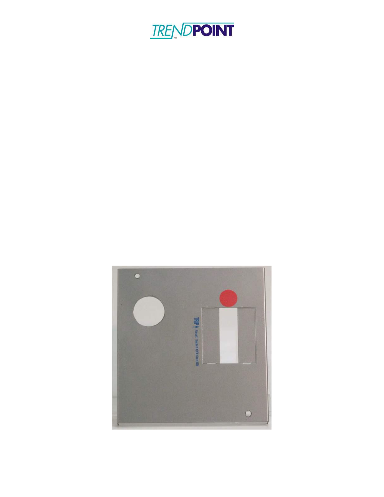
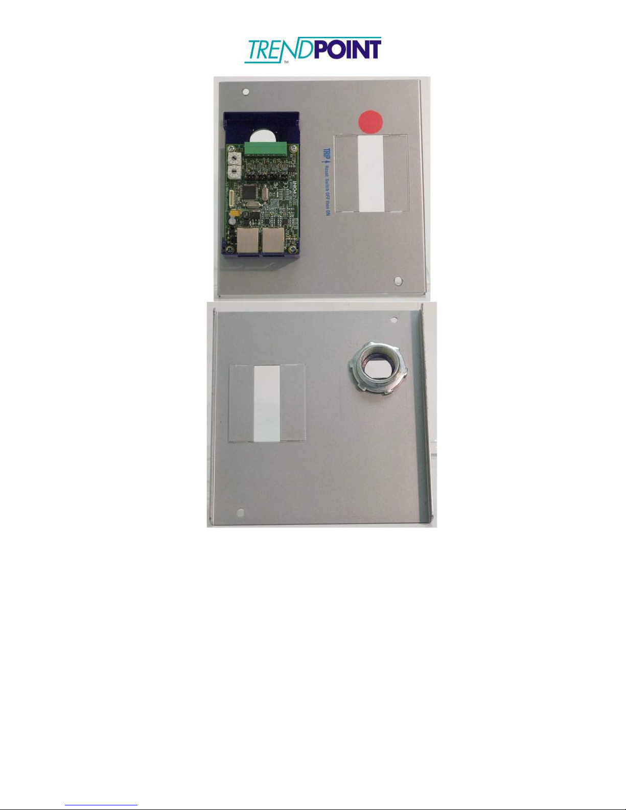
1.) Prepare the “knock-outs” on the tap box to mount the Bus Tap Cards. The EnerSure
Bus Tap Cards are fitted with a 1” standard electrical feed-through. The retention
collar is also provided with each Bus Tap Card. The 1” feed-though connector
requires a 1 ¼” “knock-out” to be made on the tap box. The Bus Tap Cards are
placed onto the tap box and secured with the retention collar provided. The cover
to the Bus Tap Card should be removed to facilitate the connection of the Current
Transformers in the following steps. Remove the four screws on the Bus Tap Card
Case to remove the cover.
Note: The location of the Bus Tap Cards is dependent on the end user’s
desired configuration and system layout. The Bus Tap Cards can be
mounted on the front cover, sides, bottom, or top of the tap box. The
illustrations in this guide show the Bus Tap Cards mounted on the front
cover of the tap box to minimize risk when installing the system on live
electrical circuits.
Warning: This installation should be performed by a licensed electrician
and should subscribe to all local, state, and federal regulations regarding
electrical work and safety standards.
Figure 21: Tap box with hole punched for EnerSure Bus
Page 41
Enkapsis & EnerSure Platform Installation Guide Rev07.2
41
Figure 22: Bus Tap Card mounted on Tap Box and Retention Collar
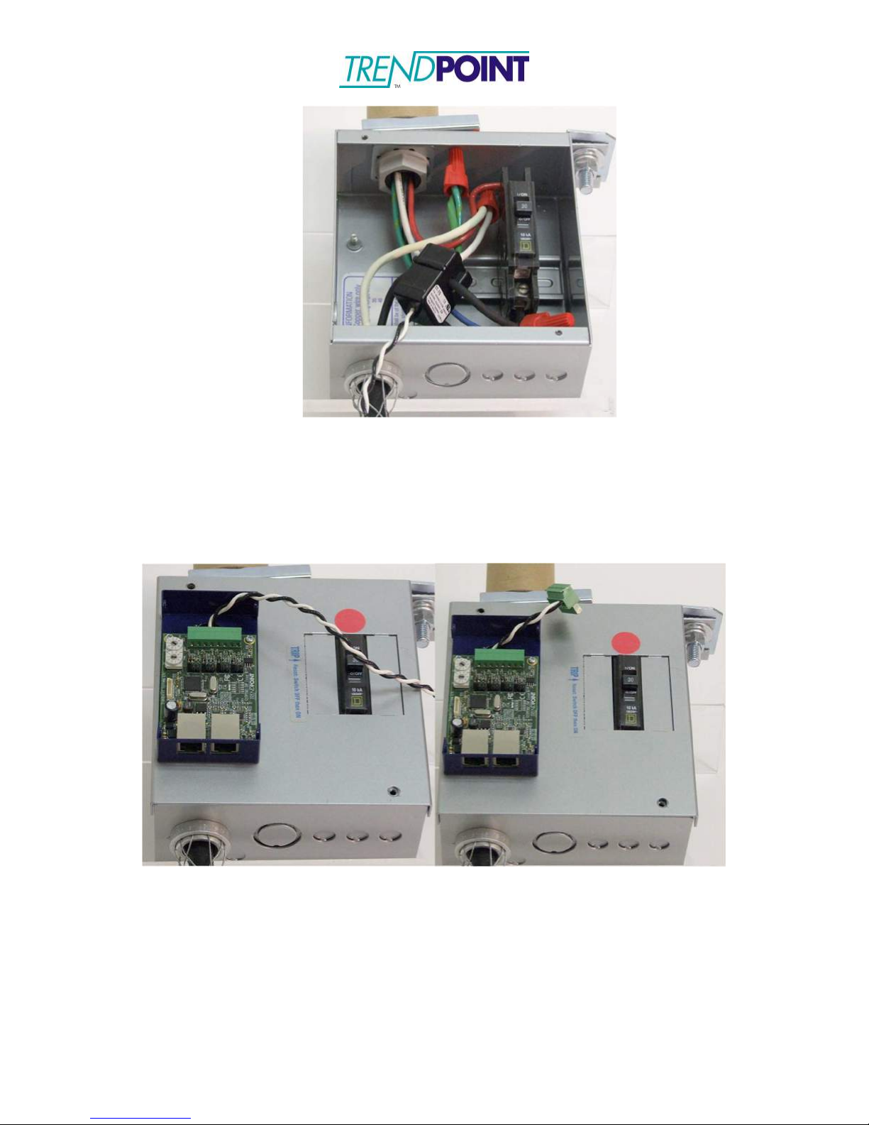
2.) Connect the Current Transformers to the circuits that are being monitored by this
system. The CT’s should be securely snapped around the wires and placed with the
label facing toward the source of power (bussway rails).
Page 42
Enkapsis & EnerSure Platform Installation Guide Rev07.2
42
Figure 23: CT Connected to Circuit
3.) Feed the CT wires through the Bus Tap Card feed-though and connect to the 8- way
connector on the Bus Tap Card. The CT wires may be cut to length. (See CT
Wiring and Jumper Positioning for CT and connector order.)
Note: Connectors may be used to allow the Bus Tap Case to be completely
removed without unsnapping the CT’s.
Figure 24: CT wires fed through the Bus Tap Card, cut to length and connected
to CT connector
4.) Set the Phase Selection jumper for the CT. This tells the EnerSure Bus which phase
of power the CT is monitoring to allow for an accurate PF, Wattage, and kWh
reading.
5.) When all CT connections have been made the Bus Tap Card needs to be addressed.
To address the card use the 10 position selector switches on the card.
Page 43
Enkapsis & EnerSure Platform Installation Guide Rev07.2
43
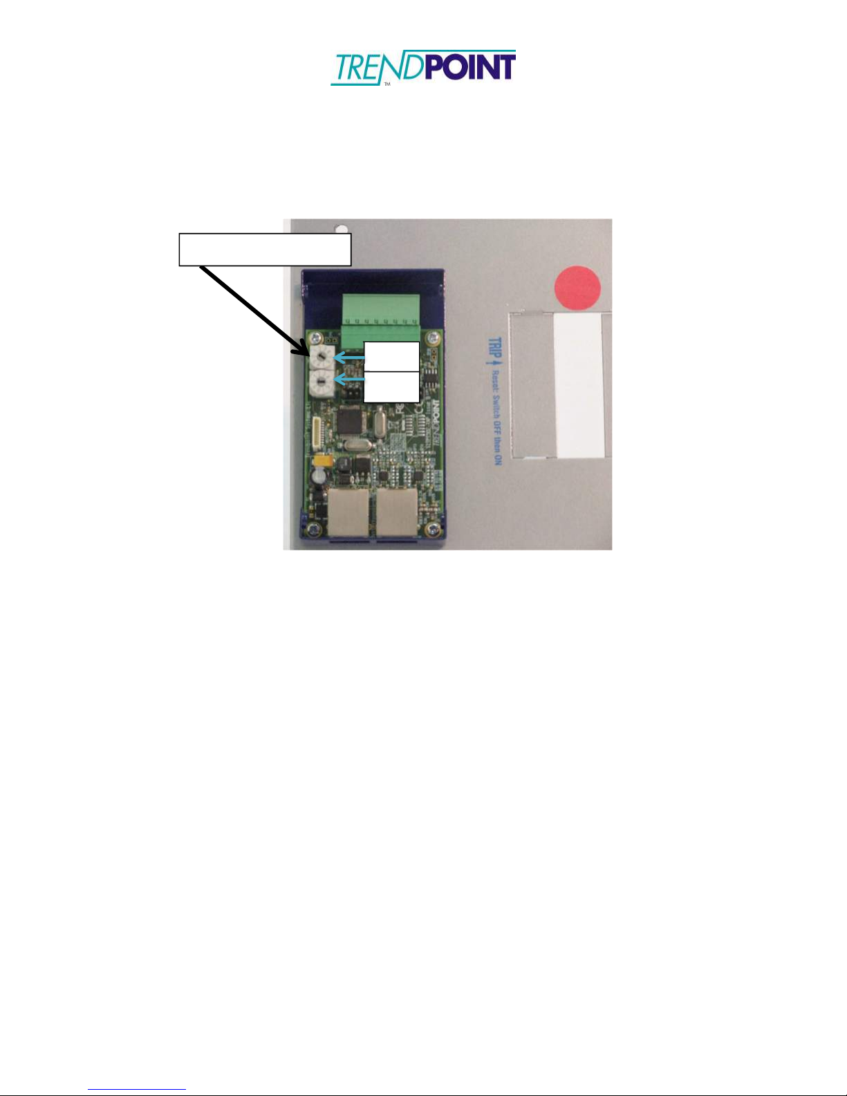
Bus Tap Card Address
One
Ten
The card should be set to an address between 1 and 30. Page 17 of this installation
guide contains a matrix to indicate the address selection and the relation to the
circuit numbers.
Figure 25: Bus Tap Card mounted on the Tap Box with CT Wires
Connected
6.) Place the cover on the Bus Tap Card and mount the cover panel back onto the tap
box if it was removed.
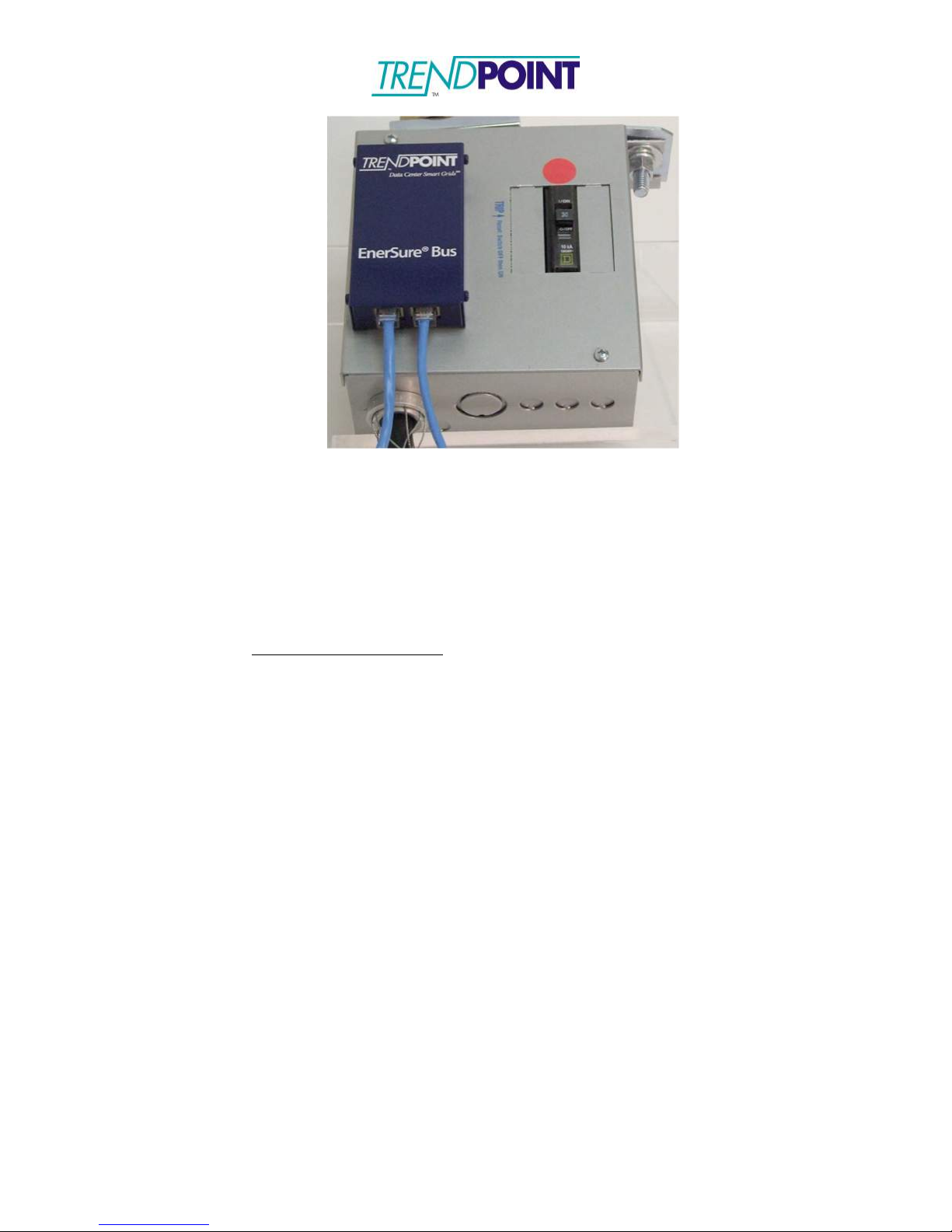
7.) The Bus Tap Cards are connected via a straight-though Ethernet cable. The
system uses all 8 wires on the Ethernet cable.
Page 44
Enkapsis & EnerSure Platform Installation Guide Rev07.2
44
Figure 26: Ethernet Cables Connected
8.) Connect the Bus Tap Cards in a “daisy chain” format and link back to the Enkapsis
Bus port.
9.) Switch the input breaker to the “ON” position. The EnerSure Bus system can be
configured via the Ethernet ports (Eth0 or Eth1) using the web interface. The data
from the EnerSure Bus is available via Modbus TCP/IP, SNMP, and BACnet.
Default TCP/IP Settings:
IP: 10.10.10.4
Subnet: 255.0.0.0
Gateway: 10.10.10.1
Page 45
Enkapsis & EnerSure Platform Installation Guide Rev07.2
45
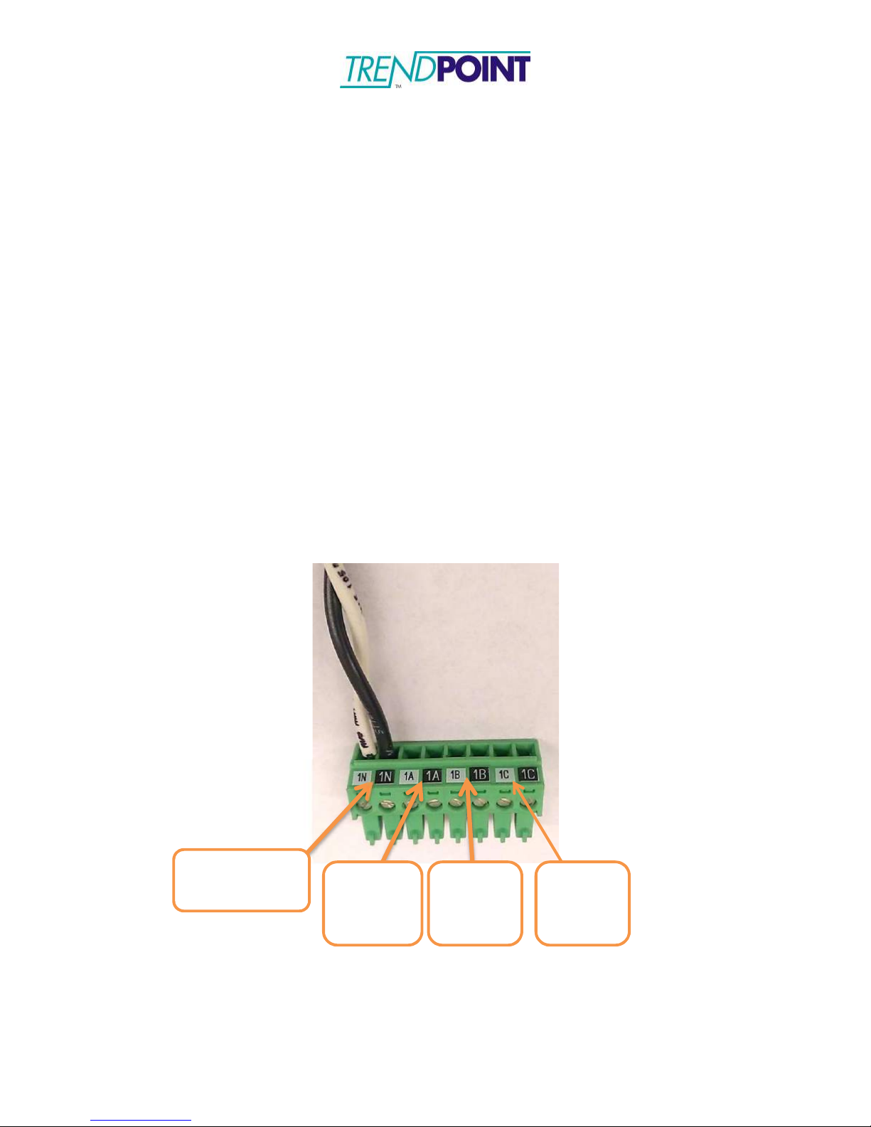
Ckt 1
Neutral (N)
Ckt 2
Phase 1
(A)
Ckt 3
Phase 2
(B)
Ckt 4
Phase 3
(C)
CT Wiring and Jumper Positioning
CT wiring and jumper positioning is very important with the EnerSure Bus system. If a
CT is wired incorrectly or a jumper is incorrectly placed it will lead to errors that must be
fixed after installation.
To avoid errors and keep installation simple, use the following guidelines when wiring
CT’s to EnerSure Bus Cards (4 or 8 circuit):
Wiring Connectors
The connectors will come pre-labeled for a 4 circuit setup (N-A-B-C). They are also
color coded to ensure the CT wires are placed correctly. Figure 20 shows circuits 1, 2, 3,
4 (Ckt 1, Ckt 2, Ckt 3, Ckt 4) in order from left to right.
4Circuit Cards:
□
Connector 1: 1N, 1A, 1B, 1C
8Circuit Cards:
□
Connector 1: 1N, 1A, 1B, 1C
□
Connector 2: 2N, 2A, 2B, 2C
Figure 27
Page 46
Enkapsis & EnerSure Platform Installation Guide Rev07.2
46
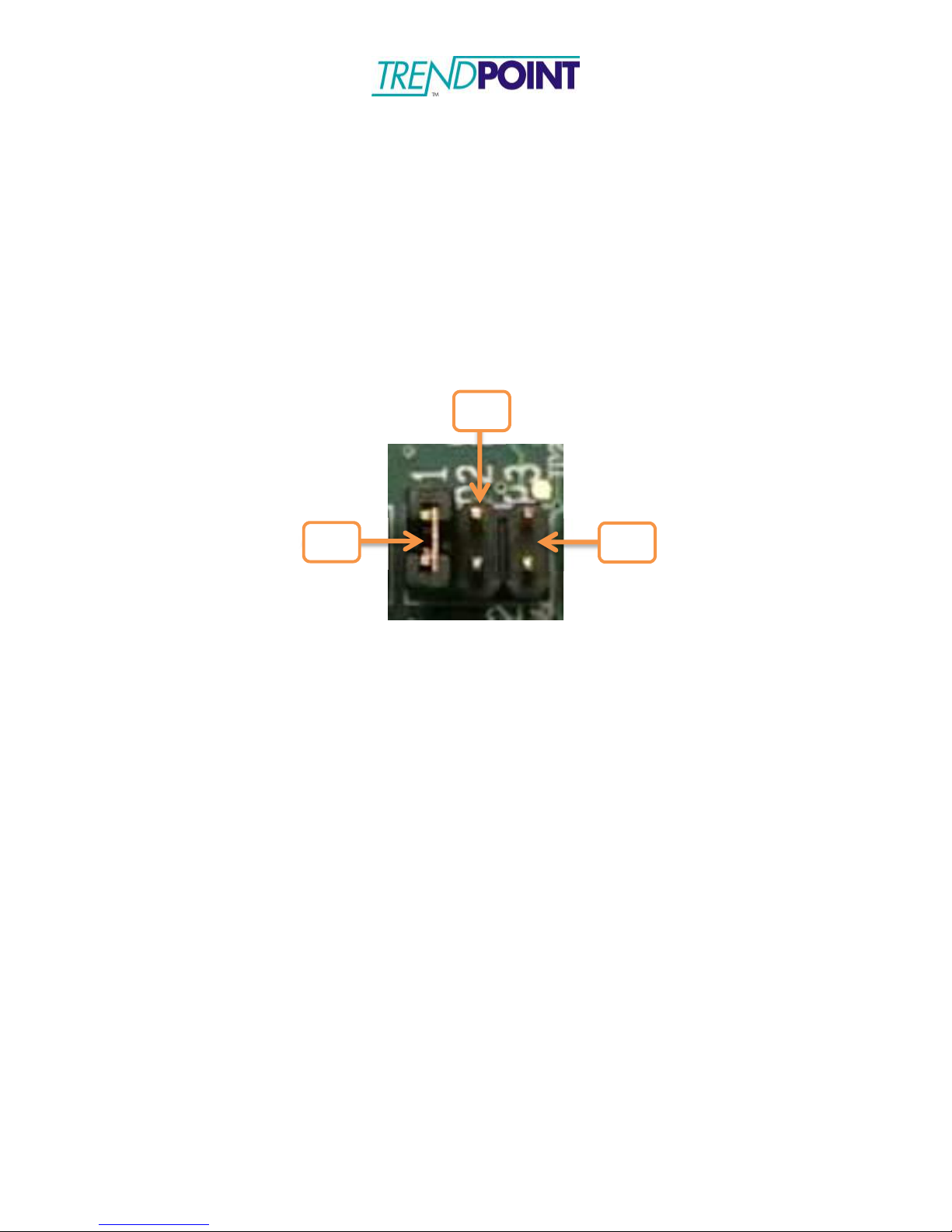
P2
P1
P3
Setting Board Jumpers
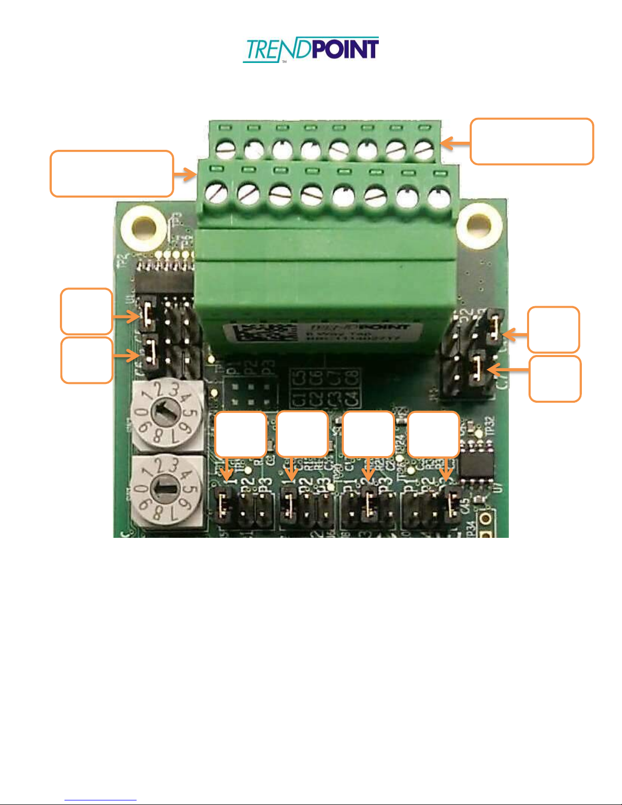
Each 4 or 8 circuit Bus Tap Card has a series of 4 or 8 jumpers, respectively, that need to
be placed correctly in order for the cards to gather proper data. These jumpers come preset in the same configuration as the labeled connectors, but they should be checked to
ensure proper setup. Figure 28 shows a close-up of a jumper and figures 29 and 30 show
the default 4 and 8 circuit jumper settings. Jumpers should be set to P1 for Phase 1 and
Neutral, P2 for Phase 2, and P3 for Phase 3.
Figure 28: Circuit Jumpers (Jumper set to P1 in image)
Page 47
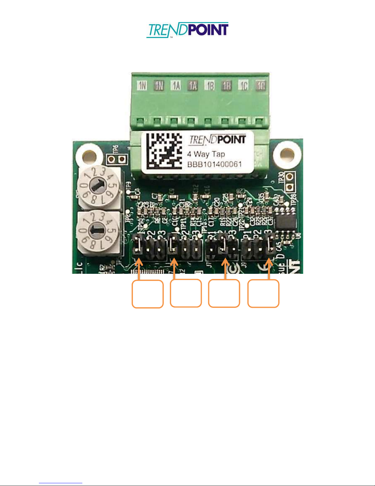
Figure 29: Default 4 Circuit Tap Card
Enkapsis & EnerSure Platform Installation Guide Rev07.2
47
Ckt 1
P1
Ckt 2
P1
Ckt 3
P2
Ckt 4
P3
Page 48
Enkapsis & EnerSure Platform Installation Guide Rev07.2
48
Figure 30: Default 8 Circuit Tap Card
Connector 2
Ckts 5, 6, 7, 8
Connector 1
Ckts 1, 2, 3, 4
Ckt 5
P1
Ckt 8
P3
Ckt 6
P1
Ckt 7
P2
Ckt 1
P1
Ckt 2
P1
Ckt 3
P2
Ckt 4
P3
Page 49

Enkapsis & EnerSure Platform Installation Guide Rev07.2
49
Address
4 Circuit
8 Circuit
1 1-4
1-8
2 5-8
Not Used
3 9-12
9-16
4 13-16
Not Used
5 17-20
17-24
6 21-24
Not Used
7 25-28
25-32
8 29-32
Not Used
9 33-36
33-40
10
37-40
Not Used
11
41-44
41-48
12
45-48
Not Used
13
49-52
49-56
14
53-56
Not Used
15
57-60
57-64
16
61-64
Not Used
17
65-68
65-72
18
69-72
Not Used
19
73-76
73-80
20
77-80
Not Used
21
81-84
81-88
22
85-88
Not Used
23
89-92
89-96
24
93-96
Not Used
25
97-100
97-104
26
101-104
Not Used
27
105-108
105-112
28
109-112
Not Used
29
113-116
113-120
30
117-120
Not Used
Address Matrix
Note: 8-Circuit Bus Tap Cards are seen as two 4-Circuit Bus Tap Cards and therefore
utilize 2 addressing positions. Example, an 8-Circuit Card addressed at address 1 utilizes
both address positions 1 and 2. The next card in the system would be address 3. This setup
allows both 4 and 8-Circuit Bus Tap Cards to be used in the same system.
Page 50
Enkapsis & EnerSure Platform Installation Guide Rev07.2
50
EnerSure Bus2.0
Bus2.0 Overview
The Installation of the Bus2.0 system involves 3 separate components:
1.) Enkapsis PQM – This unit is mounted inside a Tap Can for the Busway system that
is being fitted with the EnerSure Bus product.
2.) Bus2.0 - The Bus2.0 Cards are mounted on each tap box and connected in a “daisychain” format leading back to the Base Unit. Each Bus Tap card can support a
maximum of 4 or 8 Current Transformers (CTs.)
3.) Current Transformers - The current transformers are placed inside of each tap box. The
CTs are typically split-core type and are designed to easily snap around the wires
providing power.
Note: This manual shows how to install and configure TrendPoint’s 4-Circuit Busway
product. TrendPoint also offers an 8-Circit Busway product that installs and configures
in the same manner.
Page 51
Enkapsis & EnerSure Platform Installation Guide Rev07.2
51
Current Transformer Installation
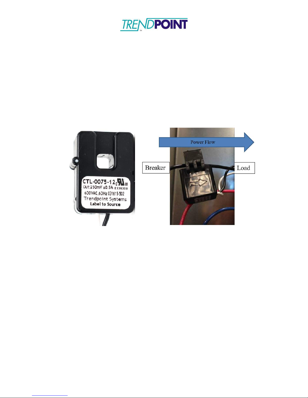
The standard CTs for the Bus2.0 system are 75 A split core CTs (Figure xx2.) The lead
lengths on the CTs can be cut to the desired length and the wires connected to the screw
terminals. The process of installation is as follows:
5.) Identify the arrow molded on the exterior of the CT or the label that says
“Label to Source”.
Figure 31: CT Orientation Marking
1.) Align the CT (Figure 31) such that the arrow is pointing in the direction of
power flow; pointing away from power source (circuit breaker) towards
load. If the CT does not have an arrow, it will have a label. The label
needs to face the power source.
Caution: Incorrectly aligned CTs may cause incorrect readings and
damage to equipment.
2.) Close the CT around the line being monitored. Ensure the CT is snapped
completely closed.
3.) Connect the CT to the corresponding circuit on the Bus 2.0 card.
Page 52
Enkapsis & EnerSure Platform Installation Guide Rev07.2
52
Bus2.0 CT Installation
WARNING
This installation procedure should be performed by a licensed electrician and should
be performed in accordance with all local, state, and federal regulations regarding
electrical work and safety standards.
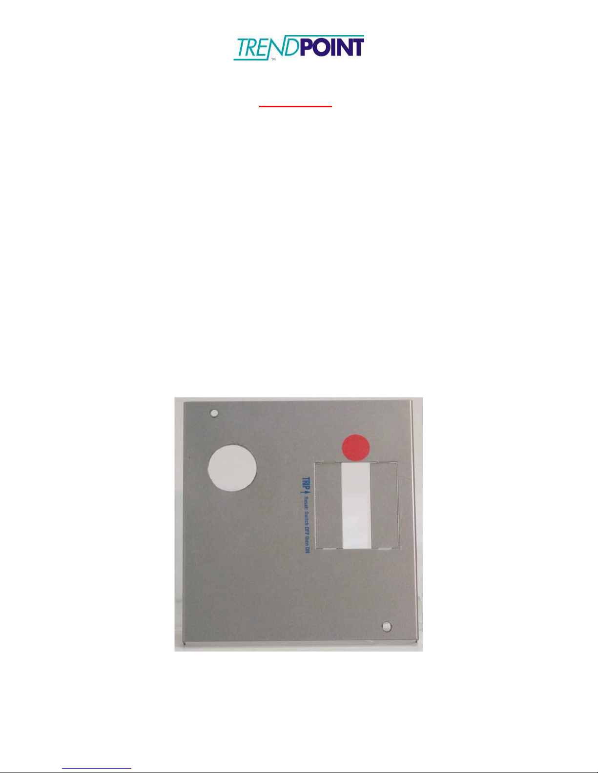
1.) Prepare the “knock-outs” on the tap box (Figure 32) to mount the Bus2.0
Cards. The Bus2.0 Cards are fitted with a 1 inch standard electrical feedthrough. A retention collar is also provided with each Bus2.0 Card. The 1”
feed-though connector requires a 1 ¼” “knock-out” to be made on the tap box.
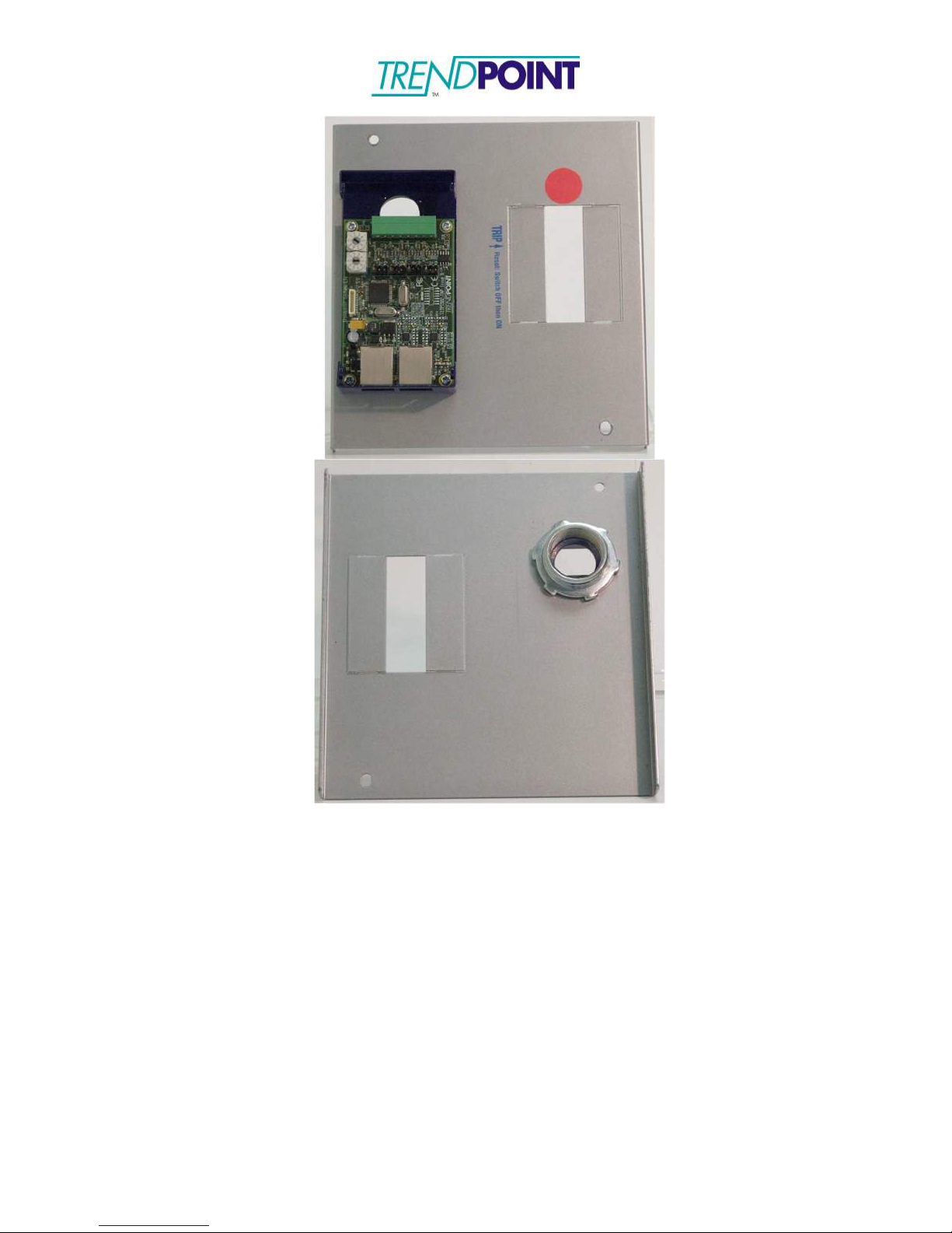
The Bus2.0 Cards are placed onto the tap box (Figure 33) and secured with the
retention collar provided. The hinged cover to the Bus2.0 Card enclosure
should be opened to facilitate the connection of the Current Transformers by
loosening the thumb screw on the Bus2.0 Card enclosure to open the hinged
cover.
Note: The location of the Bus2.0 Cards is dependent on the end user’s desired
configuration and system layout. The Bus2.0 Cards can be mounted on the front cover,
sides, bottom, or top of the tap box. The illustrations in this guide show the Bus2.0
Cards mounted on the front cover of the tap box to minimize risk when installing the
system on live electrical circuits per the safety warning above.
Figure 32: Tap box with hole punched for Bus2.0
Page 53
Enkapsis & EnerSure Platform Installation Guide Rev07.2
53
Figure 33: Bus2.0 Card mounted on Tap Box and Retention Collar
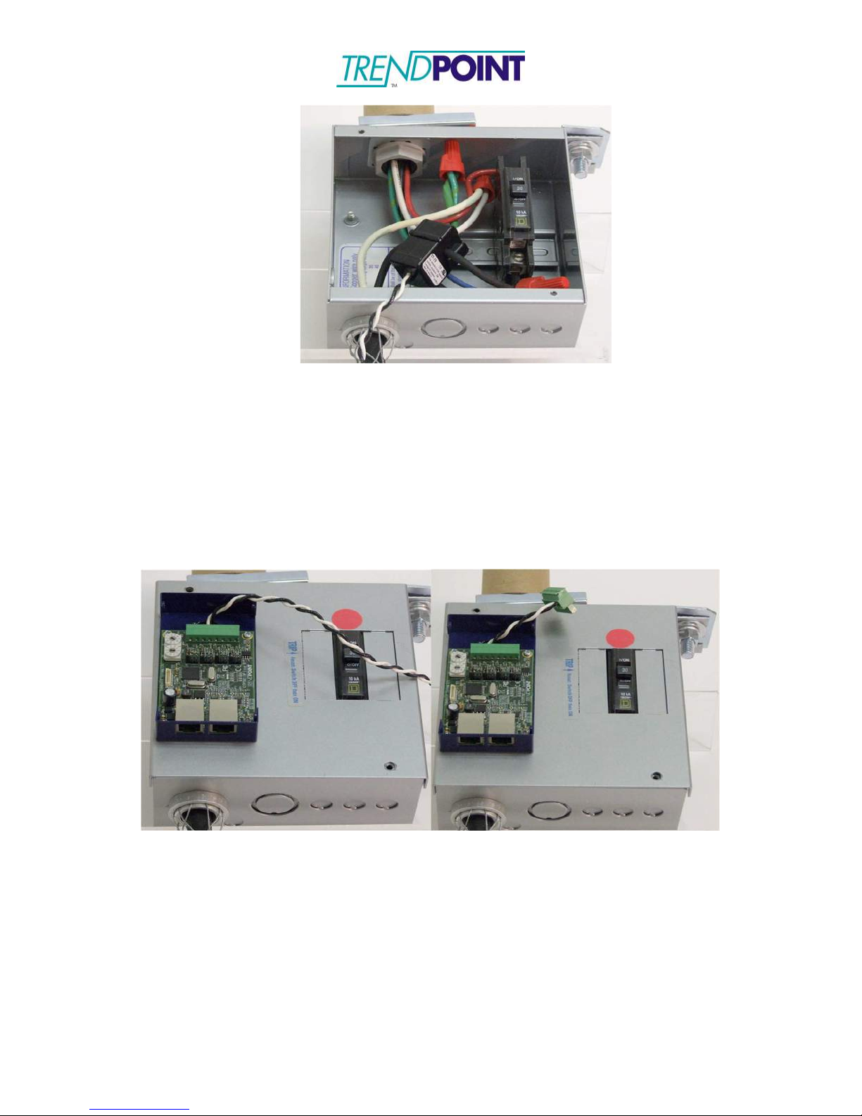
2.) Connect the Current Transformers to the circuits (Figure 34) that are being
monitored by this system. The CT’s should be securely installed per the
Current Transformer Installation instructions found in this document.
Page 54
Enkapsis & EnerSure Platform Installation Guide Rev07.2
54
Figure 34: CT Connected to Circuit
3.) Feed the CT wires through the Bus Tap Card feed-though (Figure 35) and
connect to the 8-pin connector on the Bus2.0 Card. The CT wires may be cut
to length. (See CT Wiring for CT and connector order.)
Note: Connectors may be used to allow the Bus2.0 Case to be completely
removed without unsnapping the CT’s.
Figure 35: CT wires fed through the Bus2.0 Card, cut to length and connected
to CT connector
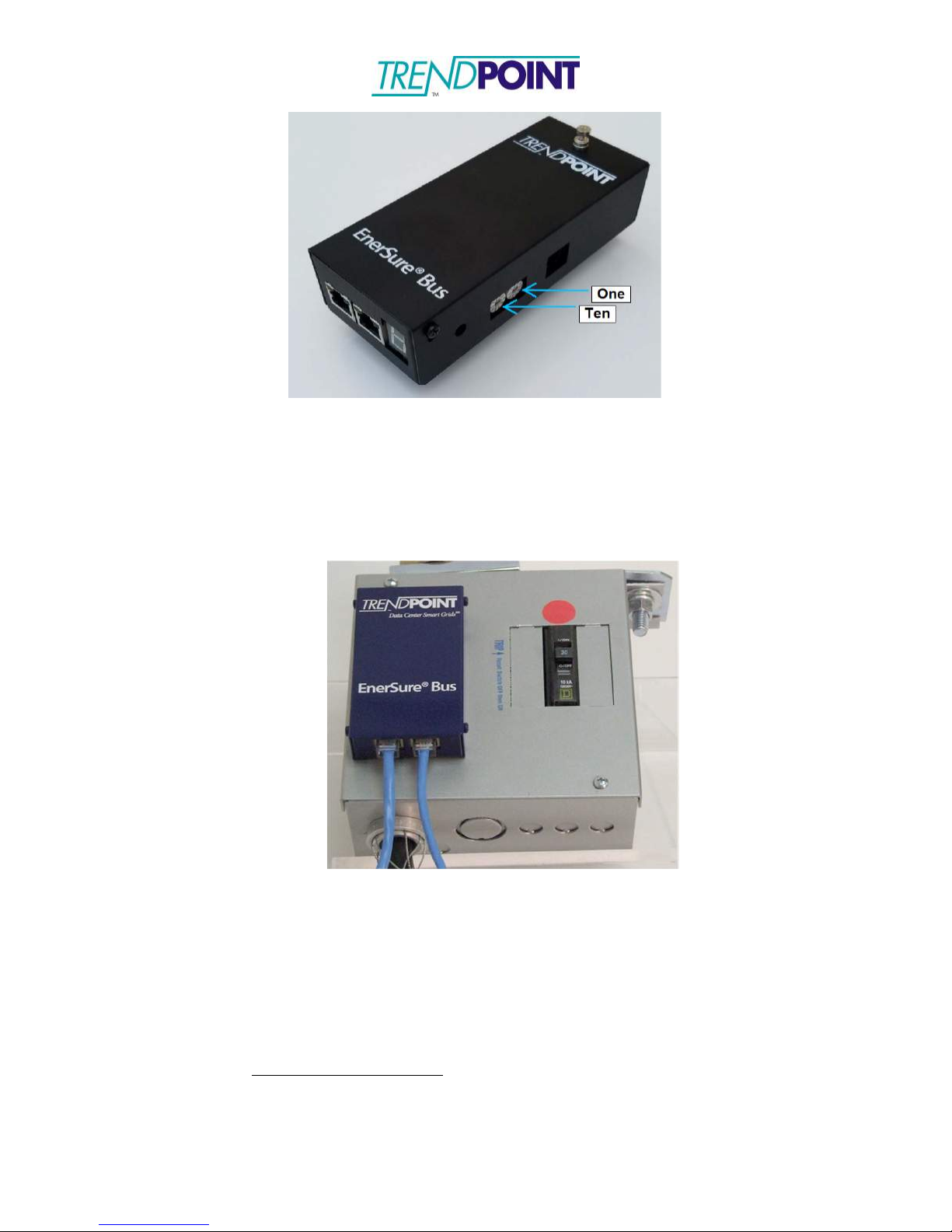
4.) When all CT connections have been made, the Bus2.0 Card address must be
set. To set the card, use the 10 position selector switches (Figure 36) to set
the applicable address.
NOTE: The card should be set to an address between 1 and 48. Page 57 of this
installation guide contains a matrix to indicate the address selection and the relation
to the circuit numbers.
Page 55
Enkapsis & EnerSure Platform Installation Guide Rev07.2
55
Figure 36: Bus2.0 Card showing address switches
5.) Close the cover on the Bus2.0 Card by securing the thumb screw.
6.) The Bus2.0 Cards are connected via a straight-though Ethernet cable as
shown in Figure 37. The system uses all 8 wires on the Ethernet cable.
Figure 37: Ethernet Cables Connected
7.) Connect the Bus2.0 Cards in a “daisy chain” format and link back to the Enkapsis
Bus port.
8.) Switch the input breaker to the “ON” position. The Bus2.0 system can be configured
via the Enkapsis Ethernet ports (Eth0 or Eth1) using the web interface. The data
from the Bus2.0 is available via Modbus TCP/IP, SNMP, and BACnet.
Default TCP/IP Settings:
IP: 10.10.10.4
Subnet: 255.0.0.0
Gateway: 10.10.10.1
Page 56
Enkapsis & EnerSure Platform Installation Guide Rev07.2
56
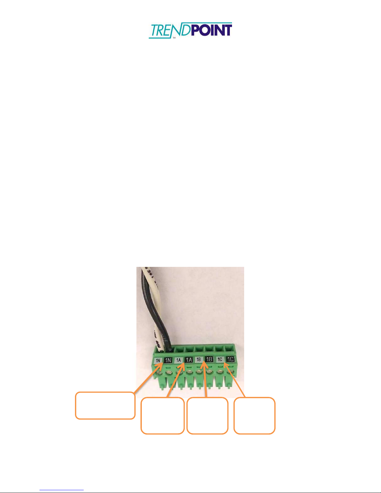
Ckt 1
Neutral (N)
Ckt 2
Phase 1
(A)
Ckt 3
Phase 2
(B)
Ckt 4
Phase 3
(C)
CT Wiring and Phase Selector
Caution: CT wiring and the Phase Selector is very important with the Bus2.0 system. If
a CT is wired incorrectly or the Phase Selector is incorrectly placed it will lead
to errors and potential equipment damage.
To avoid errors and keep installation simple, use the following guidelines when wiring
CT’s to Bus2.0 Cards (4 or 8 circuit):
Wiring Connectors
The connectors will come pre-labeled for a 4-circuit setup (N-A-B-C). They are also
color coded to ensure the CT wires are placed correctly. Figure 38 shows circuits 1, 2, 3,
4 (Ckt 1, Ckt 2, Ckt 3, Ckt 4) in order from left to right.
4-Circuit Cards:
□
Connector 1: 1N, 1A, 1B, 1C
8-Circuit Cards:
□
Connector 1: 1N, 1A, 1B, 1C
□
Connector 2: 2N, 2A, 2B, 2C
Figure 38
Page 57
Enkapsis & EnerSure Platform Installation Guide Rev07.2
57
Address
4 Circuit
8 Circuit
1 1-4
1-8
2 5-8
Not Used
3 9-12
9-16
4 13-16
Not Used
5 17-20
17-24
6 21-24
Not Used
7 25-28
25-32
8 29-32
Not Used
9 33-36
33-40
10
37-40
Not Used
11
41-44
41-48
12
45-48
Not Used
13
49-52
49-56
14
53-56
Not Used
15
57-60
57-64
16
61-64
Not Used
Setting Phase Selector
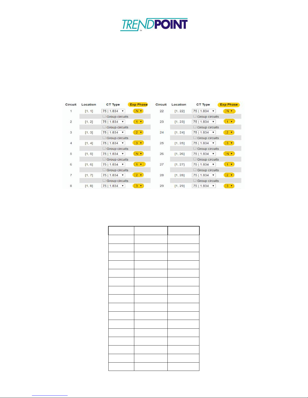
Each 4 or 8 circuit Bus2.0 Tap Card has a series of Exp Phase. Login to the Enkapsis
Web-Interface (under the “
the placement of the CT’s installed. By setting the “Exp Phase” settings this need to be
placed correctly in order for the cards to gather proper data. (Figure 39) shows a screen
shot of the Exp Phase settings in the Web Interface.
Circuit Cfg” tab)
and select the proper phasing that matches
Figure 39:
Circuit Cfg for Bus2.0
Address Matrix
(Exp Phase Select in image)
Page 58

Enkapsis & EnerSure Platform Installation Guide Rev07.2
58
17
65-68
65-72
18
69-72
Not Used
19
73-76
73-80
20
77-80
Not Used
21
81-84
81-88
22
85-88
Not Used
23
89-92
89-96
24
93-96
Not Used
25
97-100
97-104
26
101-104
Not Used
27
105-108
105-112
28
109-112
Not Used
29
113-116
113-120
30
117-120
Not Used
31
121-124
121-128
32
125-128
Not Used
33
129-132
129-136
34
133-136
Not Used
35
137-140
137-144
36
141-144
Not Used
37
145-148
145-152
38
149-152
Not Used
39
153-156
153-160
40
157-160
Not Used
41
161-164
161-168
42
165-168
Not Used
42
169-172
169-176
44
173-176
Not Used
45
177-180
177-184
46
181-184
Not Used
47
184-188
185-192
48
189-192
Not Used
Note: 8-Circuit Bus2.0 Cards are seen as two 4-Circuit Bus2.0 Cards and therefore utilize
2 addressing positions. Example, an 8-Circuit Card addressed at address 1 utilizes both
address positions 1 and 2. The next card in the system would be address 3. This setup
allows both 4 and 8-Circuit Bus2.0 Cards to be used in the same system.
Page 59

Enkapsis & EnerSure Platform Installation Guide Rev07.2
59
Startup and Use - EnerSure Bus & Bus2.0
Initial Startup
o
Make sure all electronic equipment is properly grounded before
connecting any live power.
o
Record the serial numbers of each Enkapsis PQM before installation.
o
Re-connect the power supply connector to the Enkapsis PQM. Note: If the
circuit breaker powering the power supply is turned on you will
immediately see the LED lights on the Enkapsis PQM. If the board is
currently being supplied power please turn the power off. (Note: the CPU
takes approximately 10 seconds to reboot after the unit is powered off).
o
Before communicating with the Enkapsis PQM all CT’s should be
connected.
o
Apply power to the Enkapsis PQM.
o
Connect a Cat5 cable from the Enkapsis PQM to your computer.
o Applications of RS-485 use 9600, N, 8, 1.
o
The factory default network settings are:
o
IP address 10.10.10.4
o
Subnet Mask 255.0.0.0
o
Gateway 10.10.10.1
Page 60

Enkapsis & EnerSure Platform Installation Guide Rev07.2
60
Assigning IP Address
o
To change any of the network settings configure your computer to
conform to the network settings of the Enkapsis PQM.
o
Connect either a crossover or straight thru Ethernet cable from your
computer to the Enkapsis PQM.
o
Open your web browser of choice and enter the IP address of the
Enkapsis PQM into the URL bar and click Enter.
o
You will be brought to the web interface and prompted to enter a
password (adminpass). Enter the password and click Log in.
o
In the General Settings tab you have options for static or dynamic IP
settings. To update the settings, complete the selections and click Save IP
settings. The settings are changed immediately and the board does not need
to reboot.
Page 61
Enkapsis & EnerSure Platform Installation Guide Rev07.2
61
Using the Web Interface
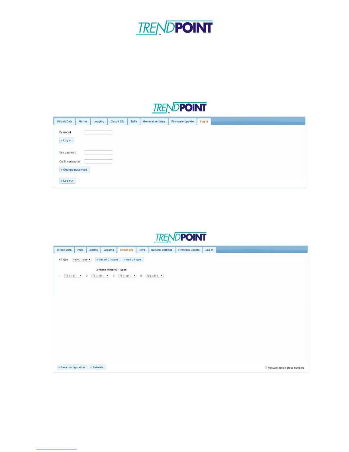
o
Open your web browser of choice and enter the IP address of the
Enkapsis PQM into the URL bar and click Enter.
o
You will be brought to the web interface and prompted to enter a
password (adminpass). Enter the password and click Log in.
o
The Enkapsis PQM web interface allows you to change the IP settings as
well as upload new firmware
o
From the Circuit Cfg tab, circuit groupings can also be assigned.
Checking the Group Circuits box between circuits will group the circuits
together. Click Save Configuration when finished.
Above – Circuit Cfg for Enkapsis PQM
Page 62
Enkapsis & EnerSure Platform Installation Guide Rev07.2
62
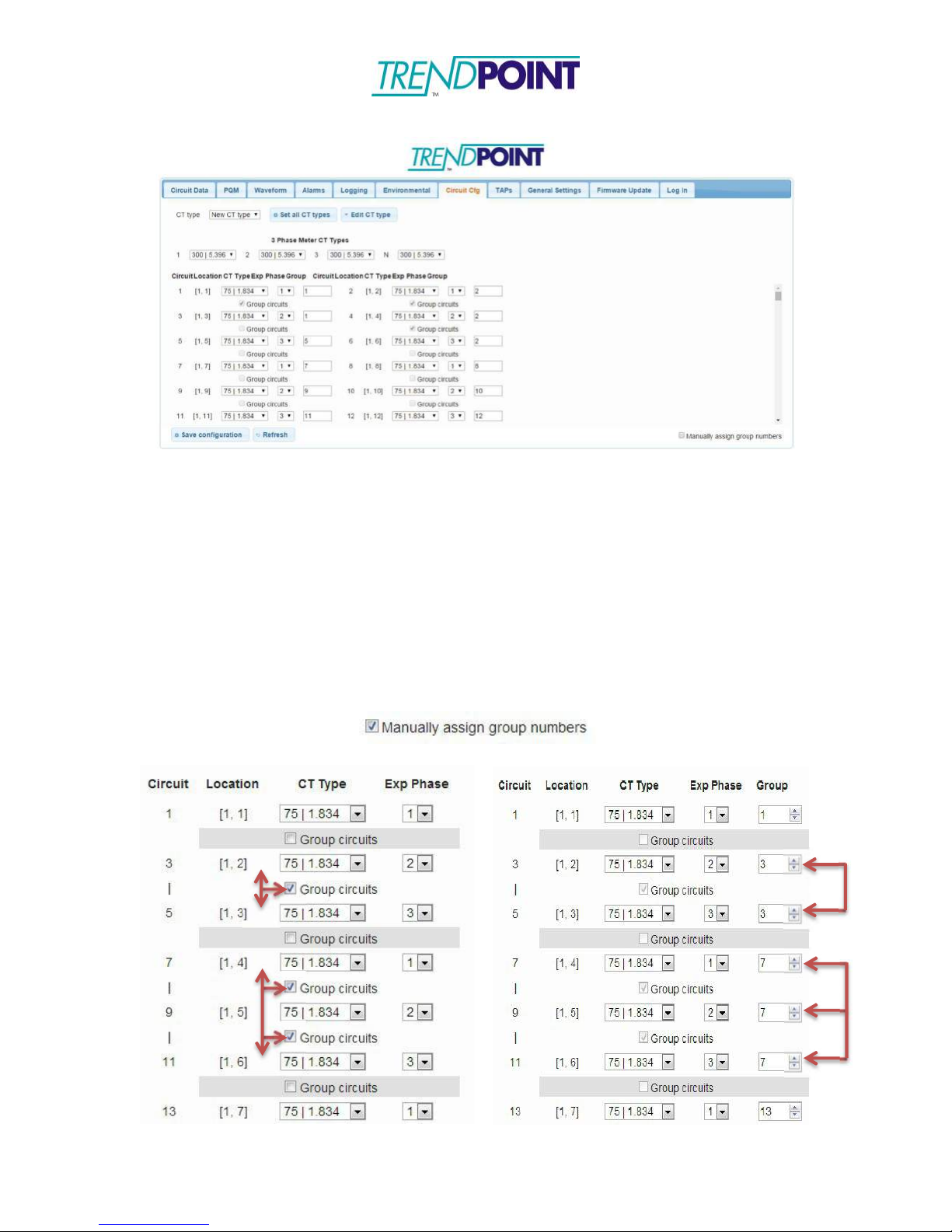
Below – Circuit Cfg for Enkapsis PQM with BCPM 2.0
Circuit Configuration
The Circuit Cfg tab allows you to make changes to the individual circuits. From the
Circuit Cfg tab, you can make the following changes:
□
Expected Phase of a Circuit
□
CT Type
□
Circuit Groupings (to distinguish between one, two, and three pole breakers)
Grouping circuits can be done manually (assigning specific group numbers) or
automatically by checking which circuits you want grouped. To manually group circuits
click the Manually assign group numbers box in the lower left corner.
Automatic Grouping Manual Grouping
Page 63
Enkapsis & EnerSure Platform Installation Guide Rev07.2
63
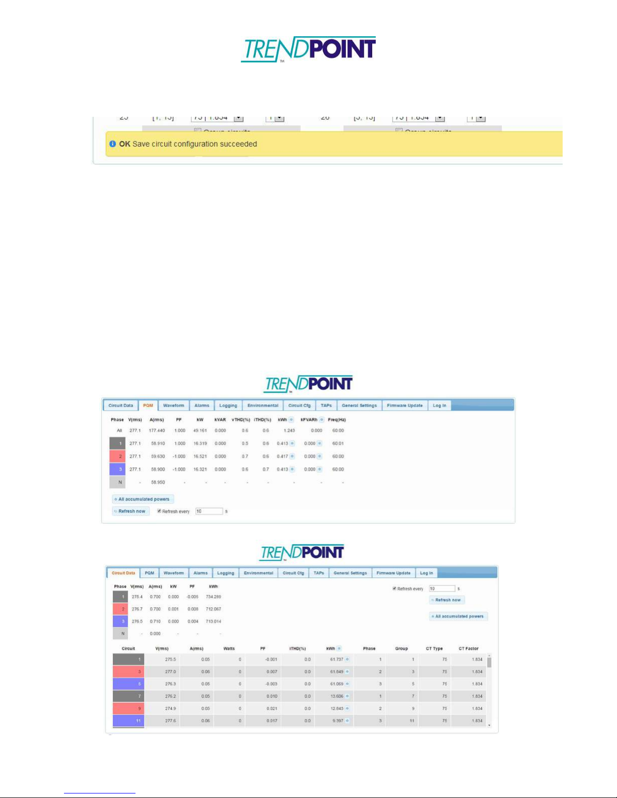
*Note: After clicking Save Configuration, wait for the system say OK Save circuit
configuration succeeded.
Sampling Live Data with Web Interface
o
After setting up the EnerSure metering parameters it is always good to run
some samples of the data in order to confirm the installation was done
properly and your system is operating correctly.
o
To sample live data:
o
Click on the PQM tab to view data from the Enkapsis PQM
o
Click on the Circuit Data tab to view data from any attached BCPM
2.0, iBCPM, or EnerSure Bus cards.
*Note: To view a summation of all connected EnerSure Bus cards,
make sure the Circuits option under Phase Summary in the General
Settings tab is selected.
o
Clicking Refresh Now will refresh the data.
Above – Data from Enkapsis PQM; Below – Data from connected BCPM 2.0
Page 64

Enkapsis & EnerSure Platform Installation Guide Rev07.2
64
Power Scaling
o
There are two selections in the General Settings tab of the web interface.
o
kWh resolution is an administrative function used when the registries of
a. High Power Mode
b.
kWh Resolution
the onboard firmware are being overloaded. Leave this setting at 0.001 at all
times.
o
High Power mode is used when circuits being monitored exceed 655
amps. When High Power mode is activated, by checking the box and
Sending the configuration change to the board, the power data received is
decreased by a power of 10 for amp and a power of 100 for watts. This
process provides needed space when the registries begin overflow at 655
amps.
Firmware Update Procedure
Your Enkapsis unit has two onboard processors that may require firmware
updates. This update procedure will assist with updating the firmware on both
processors.
Each firmware is loaded through the web interface. To load new firmware:
o
Open your web browser of choice and enter the IP address of the meter
into the URL bar and click Enter.
o
You will be brought to the web interface and prompted to enter a
password (Default: adminpass). Enter the password and click Log in.
o
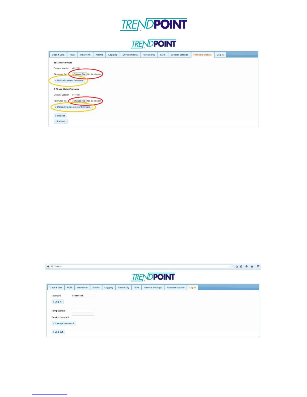
In the Firmware Update tab, you can choose which processor (System or
3 Phase Meter) you want to load a new firmware onto.
Page 65
Enkapsis & EnerSure Platform Installation Guide Rev07.2
65
o
Click the Choose File button (red circles) under the system you want to
load a new firmware. Locate the correct firmware from the firmware
update package and click OK. Click Upload firmware (orange circles) to
upload the firmware to the board.
Waveform Capture
Your Enkapsis unit has waveform capture ability. To enable waveform capture,
follow the below steps:
*Note: To use waveform capture, an SD card must be inserted into the Enkapsis
unit.
o
Open your web browser of choice and enter the IP address of the meter
into the URL bar and click Enter.
o
You will be brought to the web interface and prompted to enter a
password (Default: adminpass). Enter the password and click Log in.
o
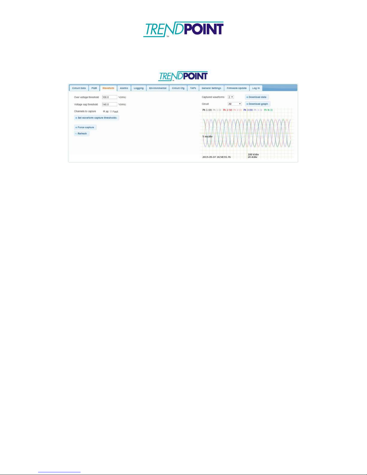
Click on the Waveform tab, from here you can set the thresholds and
channels to capture. After entering the desired settings, click Set
waveform capture thresholds to start waveform capture.
Page 66
Enkapsis & EnerSure Platform Installation Guide Rev07.2
66
o
Clicking Force capture will force the Enkapsis to capture the
current waveform.
o
There are 3 ways to view the waveform data.
o
View graph: This option will display the selected captured
waveform directly in the web interface.
o
Download graph: This option will generate download an image of
the captured waveform. This is the same image as is displayed on
the web interface.
o
Download data: This option will download a .csv file with all the
data from the captured waveform. This data can then be used to
generate graphs.
*Note: View graph and Download graph will display all data from the
captured waveform on the same graph. Use Download data to create graphs
that only show specific data.
 Loading...