

Trendnet TFC-210MSC, TFC-210S20D3, TFC-210S20D5, TFC-210MST, TFC-1000 QUICK INSTALLATION GUIDE [en, es]
...Page 1
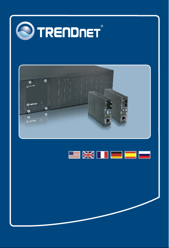
Quick Installation Guide
TFC-1000
TFC-210 Series
TFC-2000 Series
Page 2

Table of Contents
Table of Contents
Español ...........................................................................................
1. Antes de iniciar ......................................................................
2. Detalles del producto .............................................................
3. ...................................................Instalación del Hardware ....
LLCF Function ................................................................................
Technical Specifications .................................................................
Troubleshooting ..............................................................................
1
1
2
3
9
11
13
Version 02.13.2007
Page 3
1. Antes de iniciar
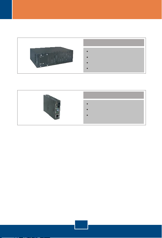
Chasis conversor de fibra TFC-1000 para conversores serie
TFC-210 y TFC-2000:
Contenidos del paquete
TFC-1000
Guía de instalación rápida
Cable de alimentación AC
Soporte de sujeción y tornillos
Conversor de fibra serie TFC-210 ó TFC-2000 :
Contenidos del paquete
Conversor de fibra
Guía de instalación rápida
Fuente de alimentación AC
(9V DC, 700mA)
1
Español
Page 4
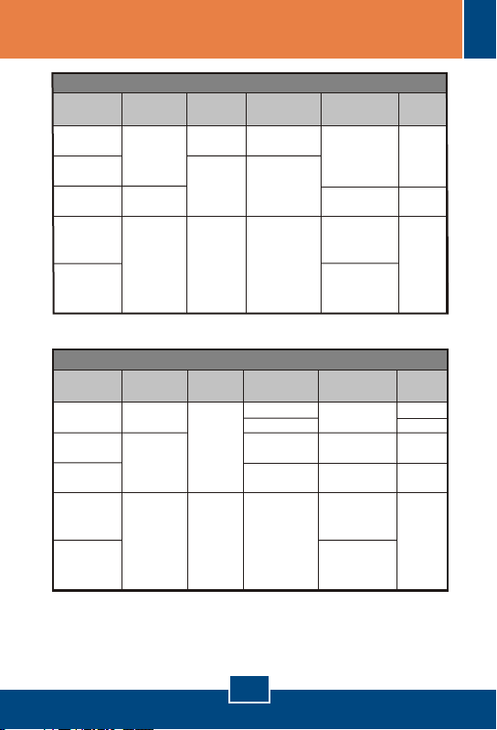
Conversores de fibra 10/100Base-TX a 100Base-FX
Nombre del
modelo
Multi/
Mono-Modo
Conector de
Fibra
Distancia
Longitud de
onda
Capacidad de
potencia
TFC-210MST
TFC-210MSC
TFC-210S20D3
TFC-210S30
TFC-210S20D5
Multi-Modo
Mono-Modo
Unidireccional/
Bidireccional
Mono-Modo
ST (Duplex)
SC (Duplex)
SC (Simplex)
2Km
30Km
20Km
TX:1310nm
(1280nm ~ 1355nm)
RX:1550nm
(1530nm ~ 1570nm)
TX:
(1530nm ~ 1570nm)
RX:1310nm
(1280nm ~ 1355nm)
1550nm
50/125um: 7.5dBm
62.5/125um: 11dBm
50/125um: 8.5dBm
62.5/125um: 8.5dBm
9/125um: 12dBm
1310nm
(1270nm ~ 1380nm)
1310nm
(1260nm ~ 1360nm)
Conversores de fibra 2000Base-T a 1000Base-SX/LX
TFC-2000MSC
TFC-2000S20
TFC-2000S10D3
TFC-2000S50
TFC-2000S10D5
Multi-Modo
Mono-Modo
Unidireccional/
Bidireccional
Mono-Modo
SC (Duplex)
SC (Simplex)
50Km
20Km
10Km
850nm
(830nm ~ 860nm)
1310nm
(1270nm ~ 1355nm)
1550nm
(1520nm ~ 1580nm)
TX:1310nm
(1280nm ~ 1355nm)
RX:1550nm
(1530nm ~ 1570nm)
TX:
(1530nm ~ 1570nm)
RX:1310nm
(1280nm ~ 1355nm)
1550nm
9/125um:15dBm
9/125um:12dBm
9/125um:19dBm
Nombre del
modelo
Multi/
Mono-Modo
Conector de
Fibra
Distancia
Longitud de
onda
Capacidad de
potencia
550M
220M
50/125um:8.5dBm
62.5/125um:8.5dBm
2. Detalles del producto
2
Español
Page 5
3. Instalación del Hardware
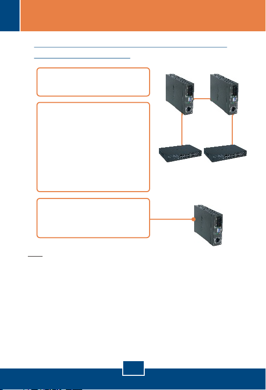
Instalación de 2 convertidores de fibra de
forma independiente
1. Conecte el cable de fibra a
los convertidores.
2. Conecte un cable de
ethernet RJ-45 desde el
puerto ethernet de los
convertidores de fibra hasta
un puerto ethernet del
conmutador (como el E
TE100-S24R o
TEG-S240TX).
3. Conecte el adaptador de
corriente a la parte posterior
del convertidor.
Nota:
– Cableado:
Cable de fibra óptica multimodo: TFC-210MST, TFC-210MSC,
TFC-2000MSC
Cable de fibra óptica monomodo: TFC-210S30, TFC-210S50,
TFC-2000S30, TFC-2000S50
Cable de fibra óptica trenzado paraTFC-210S20D3/D5, TFC-210S10D3/D5
– Los cables TX y RX deben colocarse a la inversa en la conexión de
fibra del lado opuesto.
– El TFC-210S20D3 debe quedar pareado con el TFC-210S20D5. El
TFC-2000S10D3 debe quedar pareado con el TFC-2000S10D5.
– Los puertos TX y FX en no son
autogestionables. La conexión opuesta en cobre y fibra debe ser Gigabit.
Serie TFC-200
3
Español
Page 6
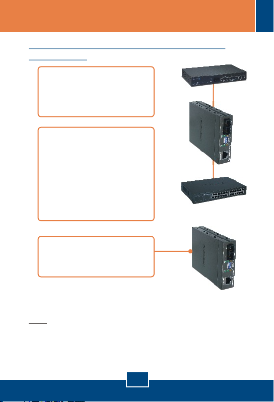
Cómo instalar un conversor de fibra a un
conmutador
1. Conecte el cable de fibra
del conversor de fibra a un
conmutador de fibra
(Ej. TE100-S810Fi)
2. Conecte un cable de
ethernet RJ-45 desde el
puerto ethernet de los
convertidores de fibra hasta
un puerto ethernet del
conmutador (como el E
TE100-S24R o
TEG-S240TX).
3. Conecte el adaptador de
corriente a la parte posterior
del convertidor.
Nota: Esta aplicación no es la indicada para TFC-210S20D3,
TFC-210S20D5, TFC-2000S10D3 y TFC-2000S10D5
4
Español
Page 7
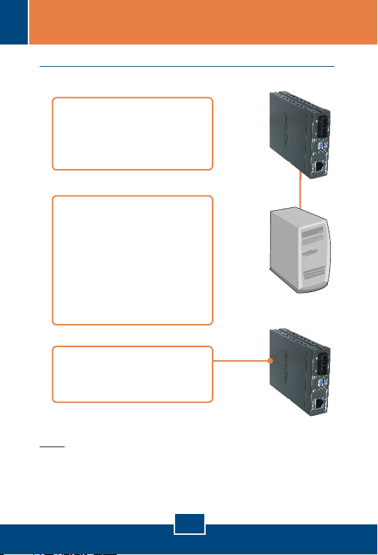
Cómo instalar un conversor de fibra a un PC
1. Conecte el cable de fibra del
conversor de fibra a un PC
con adaptador de fibra (Ej.
TE100-PCIFX+).
2. Conecte un cable de
ethernet RJ-45 desde el
puerto ethernet de los
convertidores de fibra hasta
un puerto ethernet del
conmutador (como el E
TE100-S24R o
TEG-S240TX).
3. Conecte el adaptador de
corriente a la parte posterior
del convertidor.
Nota: Esta aplicación no es la indicada para TFC-210S20D3,
TFC-210S20D5, TFC-2000S10D3 y TFC-2000S10D5
5
Español
Page 8
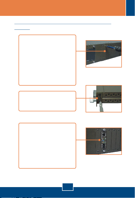
Cómo instalar un conversor de fibra a un
chasis
1. Con un destorninallador
desenrosque la tapa del
compartimiento modular del
compartimiento deseado en
el chasis y retire la tapa.
Guarde los tornillos y la tapa
en caso de que necesite
cubrir el compartimiento
modular en el futuro.
2. Fije el soporte de sujeción
en un lado del conversor de
fibra.
3. Inserte el conversor de fibra
en una ranura disponible.
Instale el conversor de fibra
con el puerto de fibra cerca
de la parte inferior del
chasis. Después apriete los
tornillos para fijar el
conversor de fibra.
6
Español
Page 9
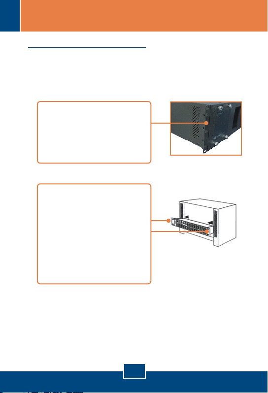
Para montaje en bastidor
El chasis puede montarse sobre un bastidor de 19 pulgadas
tamaño estándar EIA, que puede colocarse en un armario de
empalmes junto con otros equipos.
1. Fije las abrazaderas de
sujeción al panel frontal del
chasis (una en cada lado), y
asegúrelas con los tornillos
suministrados.
2. Coloque el chasis con
cuidado encima del bastidor.
Haga que la abrazadera
coincida con los orificios de
los tornillos del bastidor,
luego use los tornillos
suministrados junto con el
bastidor del equipo para
montar el chasis.
7
Español
Page 10
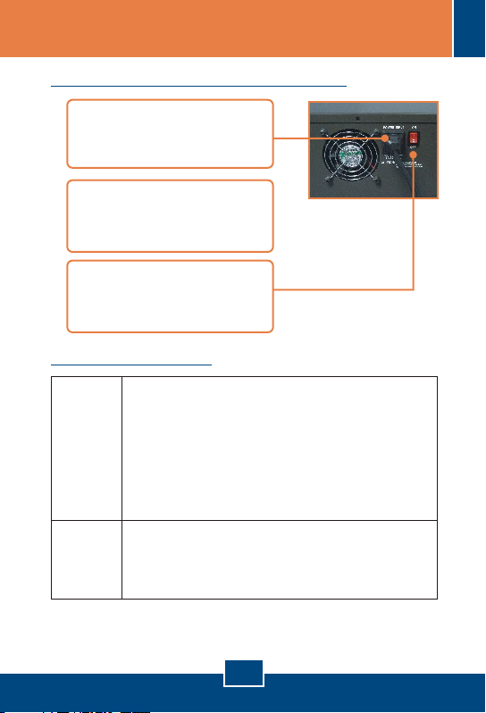
Cómo conectarlo a la alimentación
1. Conecte el cable de
alimentación suministrado a
la parte posterior del chasis.
2. Conecte el cable de
alimentación a una toma de
corriente.
3. Ponga el conmutador en
posición ON (encendido)
para encender el chasis.
Conmutadores DIP
Conmutador 1: ON (ENCENDIDO): TX Modo Full Dúplex
Serie
TFC-210
Serie
TFC-2000
* Después de cambiar las configuraciones del conmutador DIP, reinicie el
conversor de fibra.
** Las siglas LLCF significan “Link Loss Carry Forward".
Conmutador 2: ON (ENCENDIDO): FX Half Dúplex
Conmutador 3: ON (ENCENDIDO): LLCF Activado
Conmutador 4: ON (ENCENDIDO): Modo Puro
Conmutador 1: ON (ENCENDIDO): TX LLCF Activado
Conmutador 2: ON (ENCENDIDO): Fibra LLCF Activado
OFF (Apagado): TX Auto- Gestionable
OFF (Apagado): FX Full Dúplex
OFF (Apagado): LLCF Desactivado
OFF (Apagado): Modo del conmutador
OFF (Apagado): TX LLCF (Desactivado)
OFF (Apagado): Fibra LLCF (Desactivado)
8
Español
Page 11
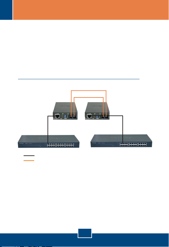
LLCF Function
LLCF allows the network administrator to quickly
troubleshoot the network connection based on the LEDs on
the Fiber Converters. When the TX port link is down, the
converter will force the fiber port link to shutdown. When the fiber
port link is down, the converter will force the TX port link to
shutdown.
LLCF (Link Loss Carry Forward) Diagram
Cable 2
Cable 3
Cable 1
Copper Cable
Fiber Cable
Media
Converter 1
Media
Converter 2
Cable 4
Below are examples on how to read the LLCF Function Table:
Example 1: If LLCF is enabled on Fiber Converter 1 and disable
on Media Converter 2, when Cable 1 link is down, Fiber Converter
1's Copper and Fiber LED and Fiber Converter 2's Fiber LED will
shut off. Fiber Converter 2's Copper LED remains on.
Example 2: If LLCF is disabled on both Fiber Converters, when
Cable 4 link is down, Fiber Converter 1's Copper and Fiber LED
and Fiber Converter 2's Fiber LED remains on. Fiber Converter
2's Copper LED will shut off.
9
Page 12
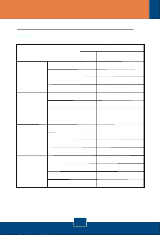
LLCF (Link Loss Carry Forward) Function
Table
Media
Converter 1
LLCF Enable
Media
Converter 2
LLCF Enable
Media
Converter 1
LLCF Enable
Media
Converter 2
LLCF Disable
Media
Converter 1
LLCF Disable
Media
Converter 2
LLCF Enable
Media
Converter 1
LLCF Disable
Media
Converter 2
LLCF Disable
Cable 1 Link Down
Cable 2 Link Down
Cable 3 Link Down
Cable 4 Link Down
Cable 1 Link Down
Cable 2 Link Down
Cable 3 Link Down
Cable 4 Link Down
Cable 1 Link Down
Cable 2 Link Down
Cable 3 Link Down
Cable 4 Link Down
Cable 1 Link Down
Cable 2 Link Down
Cable 3 Link Down
Cable 4 Link Down
Media Converter 1
Copper
LED
OFF
OFF
OFF OFFOFFOFF
OFF OFF
OFF ON
OFF ON
ON ON OFF ON
OFF
ON OFF
OFF
ON
ON OFFON ON
Media Converter 2
Fiber
Copper
LED
LED
OFFOFF OFF
OFF
OFF OFF OFF
OFF OFFOFF
OFF ON
OFF OFF
ON ON ON
OFF OFF
ON ON ON
OFF OFF
ON
ON
Fiber
LED
OFFOFF
OFFOFFON OFF
OFFOFFON OFF
OFFOFFON
10
Page 13
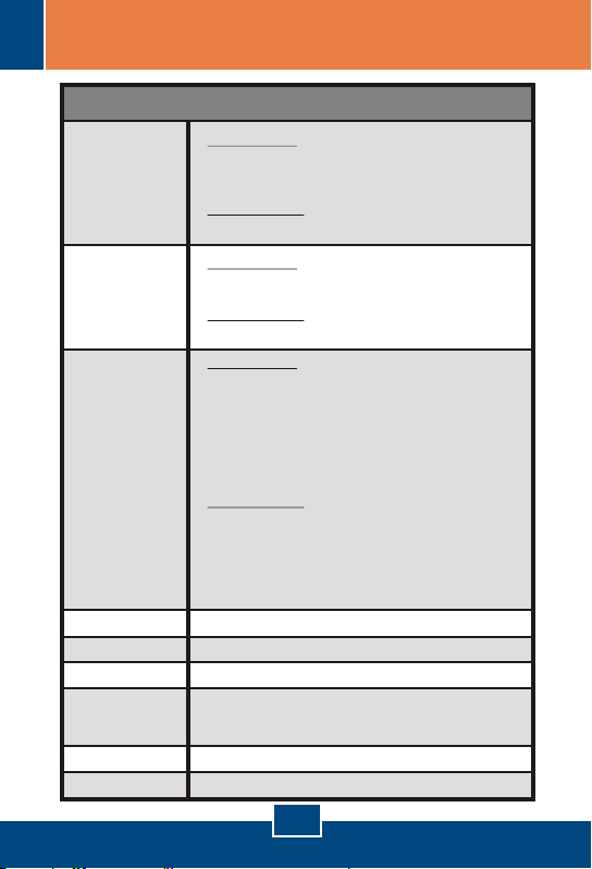
Specifications
TFC-210 series:
IEEE 802.3 10Base-T
Standards:
LED Indicators:
Cable :
Dimensions:
Weight:
Power:
Temperature:
Humidity:
Certifications:
IEEE 802.3u 100Base-TX & 100Base-FX
TFC-2000 series:
1000Base-T, 1000Base-SX/LX, IEEE 802.3ab/ 802.3z
TFC-210 series:
Power; 100Mbps, Full Duplex/ Collision, Link/Activity
TFC-2000 series:
Power; 1000Mbps, Full Duplex/ Collision, Link/Activity
TFC-210 series:
10Base-T – UTP/STP Cat. 3, 4, 5
100Base-TX – UTP/STP Cat 5
100Base-FX – Multi-Mode –
62.5/125ìm or 50/125ìm Multi-Mode Fiber Optic Cable
100Base-FX – Single-Mode –
9/125ìm Single-Mode Fiber Optic Cable
TFC-2000 series:
1000Base-T – UTP/STP: Cat. 5e or Cat. 6
1000Base-SX– Multi-Mode –
50/125ìm or 62.5/125ìm Multi-Mode Fiber Optic Cable
1000Base-LX– Single-Mode –
9/125ìm Single-Mode Fiber Optic Cable
85mm × 125mm × 25mm (W × D × H)
Around 300 g (10 oz.)
9VDC, 700mA External Power Adapter
Operating: 0°C ~ 40°C (32°F ~ 104°F)
Storage: -25°C ~ 70°C (-13°F ~ 158°F)
10 ~ 90%, non-condensing
CE, FCC
Fiber Converters
11
Page 14
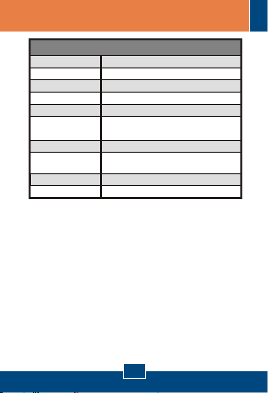
Capacity:
Material:
Power:
Power Consumption:
Cooling:
Dimensions:
Weight:
Temperature:
Humidity:
Certification:
Fiber Chassis
Ten bays for housing up to Ten media converters
Metal
AC 100~240V AC, 50/60Hz
90 Watts (Max)
One Fan
440 mm × 266mm × 133 mm (W × D × H)
Standard 19” Rack Mount Size (3U)
6.4 kg (14.2 lb.)
Operating: 0°C ~ 40°C (32°F ~ 104°F)
Storage: -25°C ~ 70°C (-13°F ~ 158°F)
10 ~ 90%, non-condensing
CE, FCC
12
Page 15

Troubleshooting
After connecting the Fiber Converter, the LEDs do not turn on. What
Q1:
should I do?
First, check that the power outlet is receiving power. Second, make
A1:
sure the power adapter is firmly connected to the Fiber Converter and
the power outlet. Third, make sure the Ethernet and the Fiber cables
are connected.
All the LEDs are on, but I can't make a connection. What should I do?
Q2:
First, verify that you are using the proper fiber cable (e.g. multi-
A2:
mode fiber cable for multi-mode converters; single-mode fiber cables for
single-mode converters). Second, verify that the TX and RX cables
have been reversed on the opposite Fiber connection. Third, power
down the Fiber Converters and the switches. Wait 15 seconds, then
plug the switches and the Fiber Converters back in.
What is the maximum distance that is supported by the Fiber Converter?
Q3:
Please refer to Product Detail for distance information.
A3:
After connecting the Chassis to a power outlet, the LEDs do not turn on.
Q4:
First, check that the power outlet is receiving power. Second, make
A4:
sure the power cord is firmly connected to the chassis and the power
outlet. Third, make sure the power switch is flipped to the ON position.
If you still encounter problems or have any questions please contact TRENDnet's
Technical Support Department.
13
Page 16

Limited Warranty
TRENDnet warrants its products against defects in material and workmanship,
under normal use and service, for the following lengths of time from the date of
purchase.
Fiber Chassis / Fiber Converters
- 5-Year Warranty
If a product does not operate as warranted above during the applicable
warranty period, TRENDnet shall, at its option and expense, repair the
defective product or deliver to customer an equivalent product to replace the
defective item. All products that are replaced will become the property of
TRENDnet. Replacement products may be new or reconditioned.
TRENDnet shall not be responsible for any software, firmware, information, or
memory data of customer contained in, stored on, or integrated with any
products returned to TRENDnet pursuant to any warranty.
There are no user serviceable parts inside the product. Do not remove or
attempt to service the product through any unauthorized service center. This
warranty is voided if (i) the product has been modified or repaired by any
unauthorized service center, (ii) the product was subject to accident, abuse, or
improper use (iii) the product was subject to conditions more severe than those
specified in the manual.
Warranty service may be obtained by contacting TRENDnet office within the
applicable warranty period for a Return Material Authorization (RMA) number,
accompanied by a copy of the dated proof of the purchase. Products returned
to TRENDnet must be pre-authorized by TRENDnet with RMA number marked
on the outside of the package, and sent prepaid, insured and packaged
appropriately for safe shipment.
14
Page 17

WARRANTIES EXCLUSIVE: IF THE TRENDNET PRODUCT DOES NOT
OPERATE AS WARRANTED ABOVE, THE CUSTOMER’S SOLE REMEDY
SHALL BE, AT TRENDNET’S OPTION, REPAIR OR REPLACEMENT. THE
FOREGOING WARRANTIES AND REMEDIES ARE EXCLUSIVE AND ARE IN
LIEU OF ALL OTHER WARRANTIES, EXPRESSED OR IMPLIED, EITHER IN
FACT OR BY OPERATION OF LAW, STATUTORY OR OTHERWISE,
INCLUDING WARRANTIES OF MERCHANTABILITY AND FITNESS FOR A
PARTICULAR PURPOSE. TRENDNET NEITHER ASSUMES NOR
AUTHORIZES ANY OTHER PERSON TO ASSUME FOR IT ANY OTHER
LIABILITY IN CONNECTION WITH THE SALE, INSTALLATION,
MAINTENANCE OR USE OF TRENDNET’S PRODUCTS.
TRENDNET SHALL NOT BE LIABLE UNDER THIS WARRANTY IF ITS
TESTING AND EXAMINATION DISCLOSE THAT THE ALLEGED DEFECT IN
THE PRODUCT DOES NOT EXIST OR WAS CAUSED BY CUSTOMER’S OR
ANY THIRD PERSON’S MISUSE, NEGLECT, IMPROPER INSTALLATION OR
TESTING, UNAUTHORIZED ATTEMPTS TO REPAIR OR MODIFY, OR ANY
OTHER CAUSE BEYOND THE RANGE OF THE INTENDED USE, OR BY
ACCIDENT, FIRE, LIGHTNING, OR OTHER HAZARD.
LIMITATION OF LIABILITY: TO THE FULL EXTENT ALLOWED BY LAW
TRENDNET ALSO EXCLUDES FOR ITSELF AND ITS SUPPLIERS ANY
LIABILITY, WHETHER BASED IN CONTRACT OR TORT (INCLUDING
NEGLIGENCE), FOR INCIDENTAL, CONSEQUENTIAL, INDIRECT, SPECIAL,
OR PUNITIVE DAMAGES OF ANY KIND, OR FOR LOSS OF REVENUE OR
PROFITS, LOSS OF BUSINESS, LOSS OF INFORMATION OR DATE, OR
OTHER FINANCIAL LOSS ARISING OUT OF OR IN CONNECTION WITH
THE SALE, INSTALLATION, MAINTENANCE, USE, PERFORMANCE,
FAILURE, OR INTERRUPTION OF THE POSSIBILITY OF SUCH DAMAGES,
AND LIMITS ITS LIABILITY TO REPAIR, REPLACEMENT, OR REFUND OF
THE PURCHASE PRICE PAID, AT TRENDNET’S OPTION. THIS
DISCLAIMER OF LIABILITY FOR DAMAGES WILL NOT BE AFFECTED IF
ANY REMEDY PROVIDED HEREIN SHALL FAIL OF ITS ESSENTIAL
PURPOSE.
Governing Law: This Limited Warranty shall be governed by the laws of the
state of California.
Note: AC/DC Power Adapter, Cooling Fan, Cables and Power Supply carry a
1-Year Warranty
15
Page 18
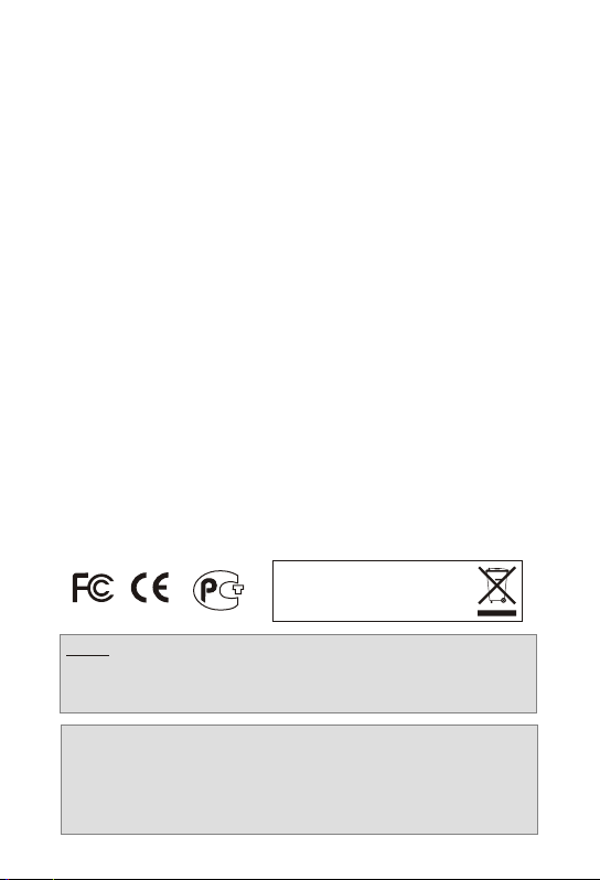
Certifications
This equipment has been tested and found to comply with FCC and CE
Rules.
Operation is subject to the following two conditions:
(1) This device may not cause harmful interference.
(2) This device must accept any interference received. Including
interference that may cause undesired operation.
Waste electrical and electronic products must not
be disposed of with household waste. Please
recycle where facilities exist. Check with you
Local Authority or Retailer for recycling advice.
NOTE: THE MANUFACTURER IS NOT RESPONSIBLE FOR ANY RADIO OR TV
INTERFERENCE CAUSED BY UNAUTHORIZED MODIFICATIONS TO THIS
EQUIPMENT. SUCH MODIFICATIONS COULD VOID THE USER’S AUTHORITY
TO OPERATE THE EQUIPMENT.
ADVERTENCIA
En todos nuestros equipos se mencionan claramente las caracteristicas del adaptador
de alimentacón necesario para su funcionamiento. El uso de un adaptador distinto al
mencionado puede producir daños fisicos y/o daños al equipo conectado. El adaptador
de alimentación debe operar con voltaje y frecuencia de la energia electrica domiciliaria
existente en el pais o zona de instalación.
Page 19
TRENDnet Technical Support
Toll Free Telephone: 1(866) 845-3673
.
US Canada
24/7 Tech Support
Europe (Germany France Italy Spain Switzerland UK)
Toll Free Telephone: +00800 60 76 76 67
English/Espanol - 24/7
Francais/Deutsch - 11am-8pm, Monday - Friday MET
Telephone: +(31) (0) 20 504 05 35
Worldwide
English/Espanol - 24/7
Francais/Deutsch - 11am-8pm, Monday - Friday MET
. . . . .
Product Warranty Registration
Please take a moment to register your product online.
Go to TRENDnet’s website at http://www.trendnet.com
20675 Manhattan Place
Torrance, CA 90501
USA
Copyright ©2007. All Rights Reserved. TRENDnet.
 Loading...