

Page 1

TEW-212APBO
Wi-Fi Inter-Building Router
User’s Guide
Page 2

Contents
TEW-212APBO________________________________________________________ 1
Overview __________________________________________________________________ 2
Features ______________________________________________________________ 3
5 Operating Modes _____________________________________________________ 4
Starting Up ___________________________________________________________ 9
Device Status page_____________________________________________________ 12
Setup Wizard_________________________________________________________ 14
Operation Mode Settings Page_________________________________________________ 14
General Configuration Settings Page____________________________________________ 15
Network Configuration Settings page ___________________________________________ 17
Wireless Configuration Settings page ___________________________________________ 19
Redirection Service _________________________________________________________ 23
Advanced Settings_____________________________________________________ 24
Firewall configuration _______________________________________________________ 24
ACL Configuring___________________________________________________________ 28
Static routing configuration ___________________________________________________ 28
DHCP Service Configuration__________________________________________________ 31
Port forwarding configuration _________________________________________________ 33
Setting up administrator password______________________________________________ 35
System Tools _________________________________________________________ 36
Clients page _______________________________________________________________ 36
Loopback Test _____________________________________________________________ 37
Configuring SNMP management_______________________________________________ 38
Site survey page____________________________________________________________ 39
Monitoring page____________________________________________________________ 40
Upgrade page ______________________________________________________________ 42
Upgrade Utility ____________________________________________________________ 44
Reboot Page _______________________________________________________________ 48
Reset page ________________________________________________________________ 48
Specifications_________________________________________________________ 49
Administration _____________________________________________________________ 50
Glossary _____________________________________________________________ 51
Page 3

Overview
The TEW-212APBO is a standalone wireless client, which provides IP
routing functionality between a Local Area Network (LAN) and a Wide
Area Network (WAN). It uses an Ethernet interface to connect to LAN, and
wireless 802.11b-based interface to connect to a Wireless Networking
System, which provides miscellaneous WAN access.
Wireless Networking System
TEW-212APBO is part of the Wireless Internet Service Provision System. It
provides access for locally connected computers to WAN, such as the
Internet. In Figure 1 shown below, the client devices are connected to the
access points (please refer to TEW-212APBO specification).
Figure 1: TEW-212APBO Solution
2
Page 4

Features
TEW-212APBO is based on indoor-outdo or architecture. An outdoor unit
with 2.4 GHz antennas is placed on the mast or roof of construction
elements. It is connected to the indoor unit via a UTP cable. An individual
computer or an entire local network can gain ac cess to the Internet by simply
connecting the TEW-212APBO indoor unit to the switch/hub. TEW212APBO is a full featured IP router with extensive firewall capabilities and
a user-friendly web interface.
• Wireless Access Point or Client (configurable)
• Router/Bridge (configurable) and Firewall
• Telecom features Built-in
• Web management Interface
TEW-212APBO can be managed via:
• FTP
• Telnet
• WWW
• SNMP (v1, v2)
It is possible to modify the following information through a web interface:
• General information
• Network LAN and WAN interfaces settings
• Wireless device settings
• DHCP server configuration
• IP Firewall
• Port forwarding
• Static routing
3
Page 5

5 Operating Modes
The TEW-212APBO supports 5 different kinds of operating modes: APRouter, AP Bridge, Station Bridge and Station Router.
AP-Router Mode
In this mode, the TEW-212APBO wireless unit plays the roles of the
wireless network Access point an d a router.
Figure 2: AP-Router m ode
4
Page 6

AP Mode
In this mode, TEW-212APBO acts as conventional wireless Access
point. The routing function is disabled. Local Network Area is
automatically set up to W irele ss.
Figure 3: AP mode
5
Page 7

Bridge Mode
When operating in this mode, one TEW-212APBO device can
connect with another TEW-212APBO device and form wireless
“bridge” interconnecting two or more local networks. Note that all
these devices must work in the same frequency channel and must have
the same SSID string. Please also note that wireless “bridge” DOES
NOT retransmits packets.
Figure 4: Bridge mode
6
Page 8

Note: The following operational modes need to be configured, refer to
upgrade page for more information.
Station – Router mode
In this mode, TEW-212APBO wireless interface works as wireless
network client (c o nne cts to th e Acces s point). Router part is active.
It must be defined which interface will be dedicated to the Local Area
Network LAN, and which to the External Network. Routing is
done by forwarding packets to the default gateway, which is set up
to External Network, so it is mandatory to define Local Network
Area interface.
7
Page 9

Client-Bridge mode
In this mode, TEW-212APBO acts as wireless card (associates to the
access point)
8
Page 10

Starting Up
To setup TEW-212APBO for the first time can be performed
through a web browser on a computer connected to the local
network. The administrator can use one of standard browsers
available (e.g., Netscape Navigator, or Microsoft Internet Explorer
versions 4.0 or later). Once the setup process is completed, TEW212APBO can be managed from any computer on the network that
has a web browser.
The steps to setup TEW-212APBO using a web browser are listed
below:
1. Launch a standard web browser on a computer connected to the
network.
2. Enter the TEW-212APBO IP address given to you from the ISP
into the URL field of your web browser (the default setting is
192.168.2.2). TEW-212APBO provides SSL (Secure Sockets
Layer) feature, so use https://192.168.2.2
to connect.
9
Page 11

If local network settings were configured correctly, then a login
screen should appear:
Input the username (the default username is “root”) and correct password
(the default password is “pass”) and click the “OK” button to pass the
security control screen. Once the correct username and password
combination is entered, a TEW-212APBO welcome screen should appear as
below:
10
Page 12

Figure 5: Welcome screen
Click on the “Setup Wizard” button on the menu bar to begin TEW212APBO device configuration (described in the following section).
11
Page 13

Device Status page
Device status page displays all information includes system, interface and
network status.
Figure 6: Device Status table
12
Page 14

The Device Status page is divided into to four parts:
System Status table - This table shows TEW-212APBO software versio n,
system uptime (after last reboot), average load, memory usage and
radio signal strengt h (RSSI).
System service and interfac es sta tus is sh o wn in “ Service/Interface
Status” table - This table shows wireless interface and system services
state. Possible values in this table can be Enabled/Disabled for
appropriate interface/service state.
Network status is shown in the “Network Status” table - This table
shows operating mode of the device, which can be “Router” for APRouter mode, “AP” – for access point mode and “Bridge” for bridge
mode.
Network statistics are shown in se parate table - This table contains
statistics for both interfaces of the TE W-212APBO – wired and
wireless. The wired interface is called LAN, and the wireless interface
is called WLAN. Each column corresponds to the statistics value of the
interfaces:
TxData – amount of data transferred
TxErrors – amount of transmit errors
RxData – amount of data received
RxErrors – amount of receive errors
Collisions – amount of network coll isions
13
Page 15
Setup Wizard
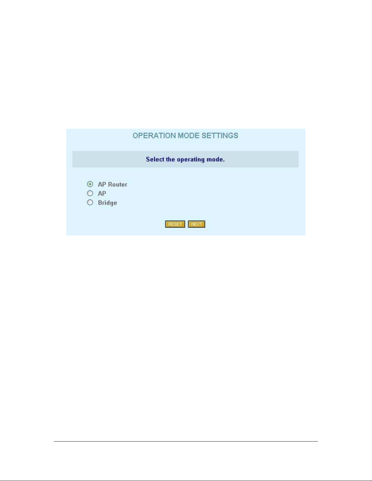
Operation Mode Settings Page
The first page of the TEW-212APBO configuration wizard is dedicated to
the device operating mode selection:
Figure 7: Device Mo de Settings page
This enables a user to select the operating mode of the device.
Click on the “Reset” button to reset the page fields to their default values.
Select one of the three device modes and click on the “Next” button to
continue the configuration wizard (For a detailed explanation of the wizard
settings, please refer to the TEW-212APBO Q uick Installation Guide).
14
Page 16
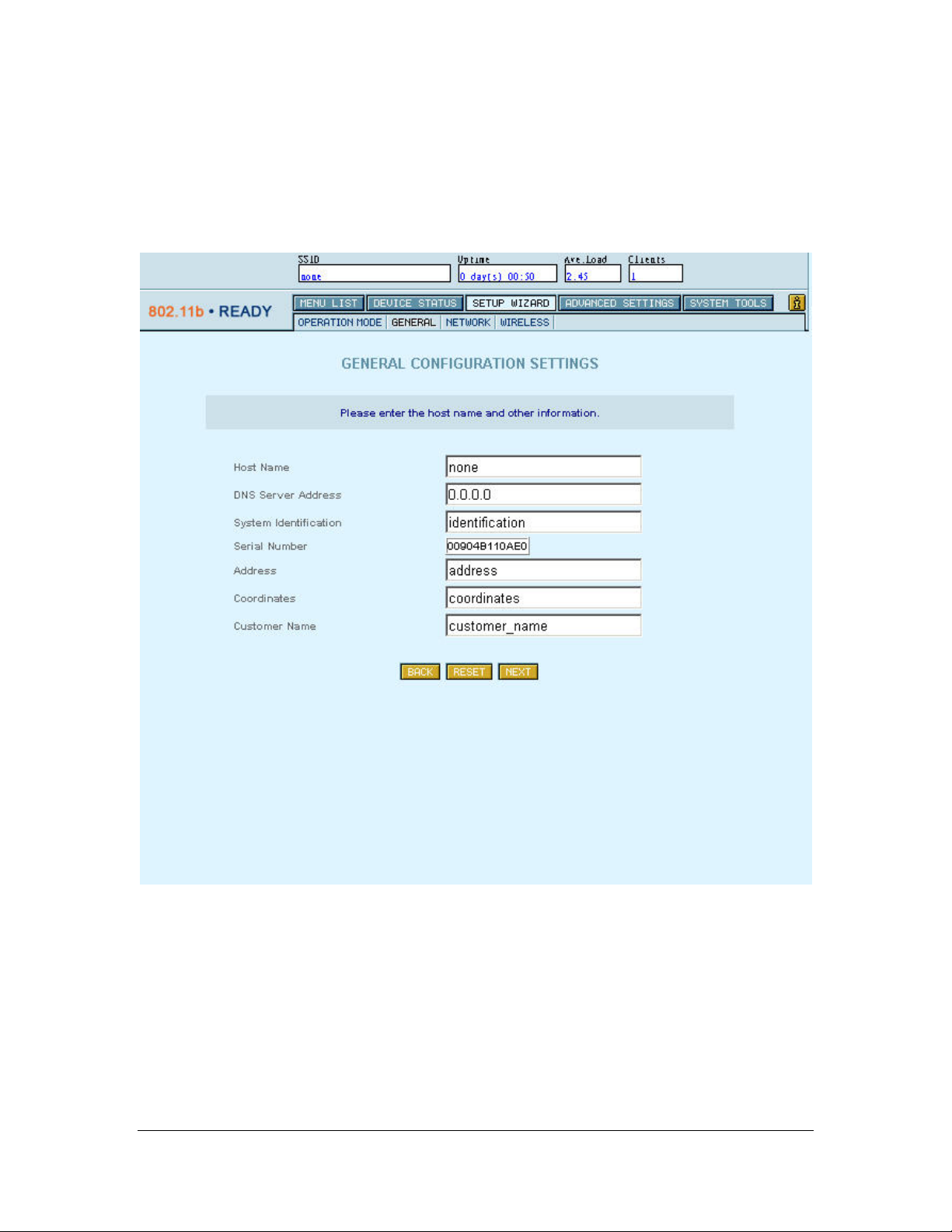
General Configuration Settings Page
Various general device parameters can be set in this page. All of those
parameters are optional.
Figure 8: General Configuration Settings page
15
Page 17

These parameters include:
Hostname – a general network parameter returned in statistics routines
DNS Server address – this Domain Name Server address is assigned
to the PCs requesting DNS address through DHCP (Dynamic Host
Configuration Protocol).
System Identification – free form system identification code for easier
device identification by the service staff.
Serial Number – A unique serial number of the TEW-212APBO
device.
Address – The location of the device.
Coordinates – GPS coordinates. Service staff fills this field when
deploying de vic e.
Customer Name – customer name, which is used for easy
identification of TEW-212APBO
Click on the “Back” button to go to the previous page, Operating Mode
Settings. Click on the “Reset” button to reset all page fields to their previous
values and cli c k on the “Next” button to continue the configuration wizard.
16
Page 18

Network Configuration Settings page
Router Mode
In Router mode, LAN (Local Area Network) and WAN (Wide Area
Network – For TEW-212APBO, this can be the enterprise networks on the
Internet) configurations can be modified using the LAN Settings and the
WAN Settings tables shown as followed:
Figure 9: Network Configuration Settings page -1 (Router mode)
17
Page 19

WAN settings must be set up according to the information provided by the
ISP. There is no such restriction on LAN settings. WAN access can be
disabled to restric t LAN users access to this network.
The masquerade setting enables the users to use the NAT (Network Address
Translation) feature of TEW-212APBO. When this option is enabled, TEW212APBO “hides” LAN addresses to the “external world”. Access to the
services, such as web services, provided by servers in the LAN, can be
achieved by using the port forwarding feature.
L Hint: Use kn own private IP addresses for the local n etwork, because if
you use public addresses, you will not be able to connect to WAN. It is
recommended to use IANA (Internet Assigned Numbers Autho rity) reserved
private address sp ace (10. 0.0.0/8, 172.16.0. 0/12 a nd 19 2. 16 8.0.0/16) .
AP Mode
In AP and Bridge mode, TEW-212APBO do es not require an active WAN
(Wide Area Network) interface, so the “WAN Interface Settings” table is not
displayed.
Figure 10: Network Configuration Settings page -2 (non-Router m ode)
Click on the “Back” button to go back to the previous page, which is
General Configuration Settings. Click on the “Reset” button to reset all
current page fields to their previ ous values and click on the “Next” button to
continue wizard.
18
Page 20

Wireless Configuration Settings page
Wireless device is configured as shown below:
Wireless Settings page (Station)
In Station mode, essential wireless device parameter is Access point SSID Service Set Identifier (Wireless Network Identifier) is the group name that
will be shared by every member of wireless network. In Station mode device
will only be able to connect with an Access Point, which has the same SSID.
19
Page 21

In AP, AP-Router or Bridge mode, additional parameter setup is provided:
Wireless settings page (AP)
This parameter is called Radio frequency channel. In Station mode, this
setting is set up automatically, but in AP (or AP-Router) mode it can be set
up manually or selected autom atically.
20
Page 22

Figure 11: Wireless Configuration Settings page
At lease two essential parameters are required to setup:
− Access Point SSID (Service Set Identifier): This is a case-sensitive
parameter to uniquely identify your radio network.
− Default Channel for BSS: It can be set up by selecting a fixed
channel or have the channel automatically assigned.
L Hint: Use the site survey utility in System Tools to verify a fixed channel
selection. This utility will help the administrator to discover unused channels,
or to check the signal strengths of other Access points of the selected
channel.
21
Page 23

In Bridge mode, there is a column field called " Bridge ID". This value
should be assign ed with different for all bridges connected to the same LAN
as a bridge ID. The value itself has no meaning if it's less or greater than
other's bridge ID. It can be from 0 to 255 . For example, it could be as signed
value "20" to the first bridge and "25" to the second.
You may desire additional security on your wireless network, which can be
achieved by using WEP (Wired Equivalent Privacy) encryption. TEW212APBO offers 64/128 bit WEP securities on wireless transmissions.
Encryption keys are combined by 5 (for 64 bit WEP) or 13 (for 128 bit WEP)
pairs of hexadecimal di git and separated by colon (e.g., 01:23:45:67 :89 for
64 bit WEP encryption keys). WEP encrypts each frame transmitted from
the radio using one of the keys from this table.
When an encrypted frame is received, it will only be accepted if it is
decrypted correctly, therefore the receiver must have the same WEP key
used by the transmitter. Each key must consist of hex digits, which is
composed of digits 0-9 and letters A-F.
L Hint: Network traffic encryption requires a significant amount of
resources, so its usage is recommended only when security is crucial.
Usually it is not used in simple commercial net works transmitting everyday
data. Also usually is more efficient to protect sensitive documents before
transmitting over network e.g., use archive program with password
protection, than encrypt all network traffic.
The Power Output, in dBm, is the strength of the RF radio signal transmitted
by wireless card. A larger num ber represents a stronger signal.
aNote: Excessive signal strength may lead to higher power consumption
and resulting in the device operating at higher temperature. Also it may
disturb operati on of th e wireless device i n th e sa me radi o fr eq uency channel .
Click on the “Back” button to return to the previous page, the Network
Configuration Settings page. Click on the “Reset” button to reset all page
fields to thei r previous values. Click on th e “Save settings” to save and to
close the configurin g w indow .
22
Page 24

Redirection Service
If a new IP was assigned and the “Save Settings” button was click to save
the network setting, a waiting and redirection message pops up as shown
below:
Figure 12: Waiting and redirection message
It indicates that the browser will be redirected to a new site (new IP). If the
new site is in a different subnet from the old one (e.g., from
192.168.2.218/24 to 168.20.1.10/24), the redirection function will not work.
The IP of the local connected computer must change to the same subnet of
the new site (168.20.1.x/24) first. And then re-click the redirection message
above or re-enter the new IP of TEW-212APBO into UR L field of browser,
to reconnect to the site.
If the new site is in the same subnet as the old site (e.g., from 192.168.2.218
to 192.168.2.100), and the redirection function did not redirect to new site
automatically, please re-click the redirection message or refresh button in the
browser.
23
Page 25

Advanced Settings
Setting up advanced TEW-212APBO settings requires some advanced
knowledge of the TCP/IP network structure and functionalities. It is
recommended that only skilled network administrators should use these
settings.
Firewall configuration
Warning: Once enable the Firewall Settings, please do not apply
“Anywhere” on Source IP Address/Mask to DROP or Reject this unit on
Destination IP Address/Mask because y ou will be restricted wh ile you
would like to make a configuration with this unit.
IP firewall configuration page provides user firewall services control. User
can add, modify or delete customized firewall rules. Main firewall page view
is shown as followed:
24
Page 26

Figure 13: IP Firewall Settings page
aNote: In AP and Bridge mode TEW-212APBO has no active WAN (Wide
Area Network) interface, so the “Firewall configuration” page is not
displayed
This page shows service state and firewall rules list. Rules are divided in two
parts – Input rules, which apply to the incoming packets, and the Outpu t
rules, which apply to the outgoing packets. User can change these rule lists
by editing exi sting rules, deleting unnecessary ones, and adding new rules.
Modification and addition of the rules is shown below:
25
Page 27

Figure 14: Firewall rule edit
The main firewall rule parameters are:
Target – this implementation of firewall control supports only two
types of rules – ACCEPT and DROP. The appropriate policy defines what to
do if packet matches rule.
Source IP Address – source IP address, can be speci fied as any
Source Netmask – source subnet, can be spec ified as any
Source port(s) – can be specified in two ways: All or a given port
range
26
Page 28

Destination IP Address – specified the same as Source IP
Destination Ne tmask – specified the same as Sourc e Netmask
Destination por t(s) – specified the same as Source port
Network protocol – network protocol which the rule affects. Can be
specified as one of TCP/UDP/ICMP or any
L Hint: If an exact port is specified, use of “any” protocol setting makes no
sense (different protocols us e their own port rang es). Use exact p rotocol , or
use several rules to specify traffic filtering on required ports.
aNote: When defining rules, avoid DENY type rules using “any” as the
address class, which can cause loss of web management connection (e.g.,
deny traffic from any to any IP address).
27
Page 29

ACL Configuring
All clients MAC are set by acceptable as default in Access Control List
function. To deny the MAC address, just click “Add New Rule” button to
add the new record. Access Control List setting is shown be low :
Figure 15: ACL Settings p age
Static routing configuration
Static routing service lets user specify static routes, which is present in
system routing table form system startup. This service is needed, when local
computers are divided into different subnets, using external router, etc. Static
routing page is shown as followed:
28
Page 30

Figure 16: Static Routing Settings page
L Hint: above figure shows default system routes, which are added
automatically , and restored after any networ k configuration . However these
routes can be edited for temporary needs.
This page provides a user static route list (present on the system), and ability
to edit, delete and add routes. Rule editing and adding is done in the
following page:
aNote: In AP and Bridge mode TEW-212APBO has no active LAN (Local
Area Network) interface, so the “Static Routes” page is not displayed
29
Page 31

Figure 17: Route editing table
Each rule in the route list consists of Device (interface) selection (can be
wireless or Ethernet), Destination address (depending on netmask, can be a
host or subnet), Gateway address (if no t specified, program uses default
interface gateway), Metric (route priority), and Netmask. If netmask is
specified as 255.255.255.255, then routing program assumes that it is the
“host” route ty pe; otherwise route specifies “net”. Note that routes are
automatically enabled when the “Save Route” button is pressed. If a rule is
specified incorrectly, no warning is provided, but rule is not added to the
system. Only skilled network administrator with in-depth knowledge of th e
network topology should use the static routing feature.
30
Page 32

DHCP Service Configuration
The Dynamic Host Configuration Prot ocol (DHCP) provides IP
configuration parameters to hosts in a client-server model. DHCP servers
assign network addr e sse s and deliver the configurati on parameters to other
(client) hosts.
DHCP server featur e is offered only in AP Router mode. This server set up
is done in the DHCP Settings table, which is sh ow n be low.
Figure 18: DHCP Server Settings page
DHCP server service can be enabled or disabled from this page. Service
state is altered, and new configuration is loaded after “Save Settings” button
is clicked. The IP Address range entered must be in the same subnet the
LAN interface of TEW-212APBO.
L Hint: Remember to set up local computers as DHCP client, when the
DHCP server is enabled. If the server detects that some computers already
have addresses from the defined range, the address is not given to the
computers.
aNote: In AP and Bridge mode TEW-212APBO has no active LAN (Local
Area Network) interface, so “DHCP Settings” page is not displayed.
31
Page 33

Click on the “Reset” button to reset all page fields to thei r previous values
and click on the “Save Settings” button to save the DHCP server setting.
32
Page 34

Port forwarding configuration
Port forwarding service provides access to locally connected computers with
dedicated serv ices by overriding the f irewall’s NAT (Networ k Address
Translation) feature. Example of such services can be chat programs, online
games, etc. Port forwarding administrator can define local computer, to
which data from specified ports of firew all are automatically redirected to
ports of this local computer. Port Forwarding Settings page is shown below:
Figure 19: Port Forwarding Settings table
aNote: In AP and Bridge mode TEW-212APBO has no active LAN (Local
Area Network) interface, so the “Port Forwarding Settings” page is not
displayed
From this page, administrator can modify port forwarding rule list by adding
new, delete and edit existing rules. Also the service can be enabled or
disabled from this page. When edi ting existing rule, or a dding new one – the
following page is displayed:
33
Page 35

Figure 20: Port Forwarding Rule editin g table
As shown in Figu re 20, a port forwarding rule consists of protocol
specification – UDP or TCP protocol, port on the TEW-212AP BO needed
for application, the local IP address and port to which arriving data will be
redirected.
L Hint: Somet imes games , chat prog rams and other ap plicatio ns may ne ed
to change thei r network settings to something like “Use Firewall” or “Use
proxy” to work properly. This setting may and sometimes should be used
with Port Forwarding service. When remote server desires to define IP
address to commun icate, you should specify not your local IP address, but
IP address of TEW-212APBO.
34
Page 36

Setting up administrator password
Administrator password is a key used to access TEW-212APBO
configuration functions in administrator security required login screen
(please refer section “Starting Up”). It will be requested when s etting up or
maintaining TEW-212APBO. This password is set up in the Administrator
Settings table shown in following:
Figure 21: Administrator Settings table
To change the password, you must enter the current password in “Old
Password” field, then enter a new password in the “New Password” field.
Re-enter the same value in the “Retype New Password” field. Use hard-toguess password, i.e. more than five characters, containing both letters and
numbers, and is not a dictionary word. Be sure to remember this password
(or write it down at a safe location) to access the TEW-212APBO
management administration features in the future. Default factory password
setting is “pass” (password is case-sensitive). This password should be
changed frequently to prevent unauthorized user access to TEW-212APBO.
Click on the “Reset” button to reset all page fields to thei r previous values
and click on the “Save Settings” button to save the administrator settings.
35
Page 37

System Tools
Clients page
Connected Clients page shows connected wireless clie nts list (AP and APRouter modes only). This list is shown i n the form of a table:
Figure 22: Connected Clients page
In the “Client MAC address” column, connected wireless card MAC
(hardware) addresses are shown.
Signal and Noise columns show radio signal and noise levels.
The column, “Rate”, shows co nnection bit rate (connection speed) in
hundreds of kilobits. This rate can be easily converted in to megabits by
dividing this number by 10. For example 110 corresponds to 11Mbits, 55
correspond to 5.5Mbits and so on.
36
Page 38

Loopback Test
Figure 23: Loopback Test pag e
Loopback test is used for wireless link diagnostics. This page shows data
transfer rate between TEW-212APBO and endpoint device. This transfer
rate is measured by sending ICMP (Internet diagnostics protocol) stream to
the end point device. Data is refreshed every second.
To start Loopback testing, enter endpoint IP address in the “Endpoint IP
address” field and click on the “Start” button in the lower right corner of
the page. Status line will show last measured data transfer rate, and the time
when this data was received from the endpoint. To stop loopback-testing,
click on the “Stop” button.
aNote: Due to the natur e of thi s test , test d ata is stored in the web br owser
applet area. Clic king t he “Refresh” or “Back” buttons when tes t is runni ng
will stop the test and clear the collecte d test data.
37
Page 39

Configuring SNMP management
SNMP (Simple Network Management Protoc ol) service is configured in the
SNMP Settings page. This page is used for setting up read-only and readwrite communities:
Figure 24: SNMP Settings
Community strings are used for SNMP authentication purposes. It is
possible to allow or deny IP address groups from accessing TEW-212APBO
using SNMP. IP address and netmask combination 0.0.0.0/32 means “ANY”
IP address. It could be setup by a specified IP, ex 192.168.2.100/32, or by a
group, ex 192.168.2.0/24.
L Hint: For security purposes, use only local IP addresses for Read/Write
access
Click on the “Reset” button to reset all page fields to their default values and
click on the “Save Settings” button to save the SNMP setting.
38
Page 40

Site survey page
Figure 25: Site Survey Test Results page
Site survey test shows the load situation in the wireless network. Using this
test, user can scan for active Access Points; check the operating channels
and their respective signal/noise levels.
L Hint: Because wireless card is scanning through all radio frequency
channels, the page load i ng time is mu ch lo nger w he n compa re d to the o the r
TEW-212APBO management pages. Use the rescan button to check
signal/noise levels when deploying new Access Points in the existing
wireless network.
39
Page 41

Monitoring page
Figure 26: Monitoring page
The Monitoring menu shows TX/RX statistics graph. These statistics show a
five-minute average traffic rate over t he last 24 ho ur s peri od. RX (green)
indicates incoming (Received) traffic and TX (red) indicates outgoing
(Transmitted) traffic.
The TX/RX monit oring is restarted on every TEW-212APBO reb oot. The
reason is that TEW-212APBO has no real time clock, and the time used is
relative to TEW-212APBO restart. The first statistics appear as 2 points after
5 minutes after TEW-212APBO. Normal view is acquired 10 minutes and
later after TEW-212APBO reboot. Click on the 'Show' button is needed
when first time the TX/RX statistics applet appears in browser window.
Next time clic k 'Refresh' button which appears instead of 'Show' button to
get newer TX/RX statistics.
You can also manipulate on TX/RX graph time interval. There are two dropdown menus used for this purpose. The first one is used to choose the
interval starti ng hou r . It is possi ble to choose any hour fro m the la st 24 hou rs ,
but choice can be l imited to fewer hours because of TEW-212A PBO reboot.
The second drop-down is used to choose time interval duration in hours. The
possible choices are from 1 to 25 hours, but it also can be limited to fewer
hours because of TEW-212APBO reboot. Sometimes you can g e t 24 instead
of 25 hours limit because relative time is even to hour range.
40
Page 42

aNote: On older firmware versions, only 'Refresh' or 'Show' buttons are
available, but they have the same behaviour.
41
Page 43

Upgrade page
a Important! Do not enter thi s page if there is no n eed to upgrade TEW-
212APBO. Simply click on the “Reset” button, if no upgrade is necessary.
Entering this page will put the device into UPGRADE mode. All of the
device functions will be SUSPENDED. Once the device enters the
UPGRADE mode, it can only be upgraded or rebooted.
L Hint: Because upgrade is done using the WEB management screen, all
management pages still work, so it is still possible to configure TEW212APBO before rebooting it.
aNote: Upgrade function on WEB-base management supports ONLY from
previous version firmware to later one which provide the same operational
modes. I.e. Upg rade from 2.00 AP vers ion to 2.01 AP version, or 2.00
Station version to 2.01 Station version.
Figure 27: Upgrade page
TEW-212APBO firmware is upgraded using the “Upgrade” page. In this
page, the current firmware version is shown. If there is a need to update this
42
Page 44

firmware, a valid firmware file must be selected first. Click on the “Browse”
button to do th is. After clicking this button – a fil e selection dialog should
appear:
Figure 28: Firmware file selection dialog
When firmware file is selected, its name is shown in the “Firmware” f ield.
Then click on the “Upgrade” button to upgrade firmware.
A “System Firmware Upgrade Process” screen will be displayed and
firmware should be upgraded as shown below:
Figure 29: System Firmware Upgrade Process Status
43
Page 45

A percentage will be showed on the status bar to indicate the upgrade status.
After completed the firmware upgrade, the T EW-212APBO device will be
rebooted automatically.
aNote: The new firmware file overwrites the old one completely. All
custom TEW-212APBO configuration settings will be reset to the default
values. Write down all configuration settings to be preserved, and set up
them, when TEW-212APBO starts after firmware upgrade. Initial TEW212APBO setup is described in the “Starting Up” chapter of this manual.
Upgrade Utility
TEW-212APBO can also be configured as a wireless station, but the unit
requires full firmware upgrade, which can be done ONLY with U pgrade
utility.
Therefore the TEW-212APBO comes with an upgrade utility,
“upgrade.exe”, to allow the user to perform the task. The program runs
under MS Windows 2000 family and MS Windows XP. Before the pr ogram
is executed, the firmware should be located first. It can be found under the
root directory in the CD.
When executing the program, the following screen should appear:
Figure 30: Upgrade utility
44
Page 46

Step 1 In the Host address field; enter the TEW-212APBO IP address for
which the firmware is to be upgraded.
Figure 31: Fill in the IP address
45
Page 47

Step 2 Enter the root pas sword and choose Full up grade to switch from AP
mode to Station mode or vise versa or Software upgrade to perform
version’s upgrade i.e. AP 2.0 to AP 3.0 or Stat ion 1.0 to Station 2.0.
Figure 32 root password is required
Step 3 Specify the TEW-212APBO firmware file, before clicking on t he
“Upgrade” button.
Figure 33 Specify firmware locations.
46
Page 48

Step 4 When the process is completed, it will be indicated in the upgrade log
window.
Figure 34 Upgrade finished.
47
Page 49

Reboot Page
Click on the “Reboot” button to reboot TEW -212APBO device via web
management. All functions will be stopped while the device is rebooted.
Reset page
To reset the TEW -212APBO device to the fact ory setting, click on the
“Reset” button. A waiting & redirection message should be shown as below
(for the redirection service, please refer to the redirection service section for
detail):
aNote: All customized TEW-212APBO co nfiguration settings will b e reset
to the default values. Wri t e do wn any configuration changes to be preserved,
and set up them, when TEW-212APBO starts after reset. Initial TEW212APBO setup is described in the “Starting Up” chapter of this manual.
48
Page 50

Specifications
Hardware
CPU ETRAX-100LX
RAM 16 MB
Flash Memory 4 MB
Ethernet 10/100 Mbit
Wireless IEEE 802.11b
Operating system
Linux version 2. 4.1 4.
Network Subsystem
TCP/IP protocol suite
Firewall
Packet filtering
Masquerading (NAT)
Port forwarding
DHCP
DHCP server for one interface (Ethernet)
SNMP
802.11 MIB support (read write)
MIB-I, MIB2 support (read only)
Routing
Static routing only
Wireless
Wireless client mode support.
Wireless access point mode support
Wireless bridge mode support
WEP-64bits, WEP-128bits encryption support
49
Page 51

Administration
Web
Access to all user functions through web browsers (Java Script must be
enabled)
Dynamic configuration changes (no reboot necessary)
Telnet
All console features
Scripting
User script support (available on the Pro version)
SNMP
802.11 MIB support (read write)
MIB-I, MIB-II support (read only)
Separate community strings for read and write support, standard SNMP trap
support.
50
Page 52

Glossary
Symbols:
10BaseT 10 Mbps/baseband/twisted pair. The IEEE standard for twisted
pair Ethernet.
IEEE 802.11b The IEEE standards for the definition of the Wireless high
speed (11Mbit) protocol for wirele ss communication.
A
Authorization the process of determining what types of activities a user is
permitted to undertake. Usually, authorization is in the context of
authenticatio n: o nce y ou have authenticated a user, they may be authorized
for different types of access or activity.
B
Backbone The primary connectivity mechanism of a hierarchical distributed
system. All systems, which have connectivity to an i ntermediate system on
the backbone, are assured of connectivity to each other. This does not
prevent systems from setting up private arrangements with each other to
bypass the back bone for reasons of cost, performance, or security .
Bandwidth Technically, the difference, in Hertz (Hz), between the highest
and lowest frequencies of a transmissi on channel. However, as typically
used, the amount of data that can be sent through a given communications
circuit. For exam ple, typical Ethernet ha s a bandwidth of 100Mbps.
bps bits per second. A measure of the dat a transmission rate.
D
DHCP Dynamic Host Configuration Protocol. A service that lets clients on
a LAN request configuration information, such as IP host addres ses, from a
server.
51
Page 53

DNS Domain Name System. The distributed name/address mechanism used
in the Internet. It comprises distributed online databases that contain
mappings between hu m an-read able names and IP addresses, and servers,
which provide translation services to client applications.
Domain A part of the DNS naming hierarchy. Syntactically, an Internet
domain name consists of a sequence of names (labels) separated by periods
(dots), e.g., “machine.company . com”. See DNS.
E
Ethernet A common, 10Mbps local area network technology invented by
Xerox Corporati on at the Palo Alto Research Ce nter. Ethernet is a best-eff ort
delivery system that uses CSMA/CD technology. Ethernet can be run over
thinwire coaxial cable (10BASE2), thickwire coaxial cable (10BASE 5),
twisted pair cable (10BASET), or fibre optic cable.
F
Filter Within the router, a filter is a process used to select which packets
will be processed by the router, and which will be ignored or discarded.
Selection may be based on addresses or protocol type.
Firewall A system or combination of systems that enforces a boundary
between two or more netw or ks.
FLASH A new memory technology, which combines the nonvolatile
features of EPROMs with the easy in-system reprogramming of
conventional volati le RA M. See EPROM.
G
Gateway The original Internet term for what is now called router or more
precisely, IP router. In modern usage, the term “gateway” and “application
gateway” refers to systems, which perform translation from some native
protocol, or physical data format to another. Examples include electronic
mail gateways, which translate between X.400 and RFC 822 mail message
formats. See router.
H
52
Page 54

Host An (end-user) computer system that connects to a network, such as a
PC, minicomputer of mainframe.
I
ICMP Inter net Control Message Protocol. The TCP/IP protocol used to
handle errors and c ontrol messages at the IP layer. ICMP is part of the IP
protocol. Gat e ways, routers and hosts use ICMP to send reports of problems
about datagrams back to the original source that sent the datagram.
Interface One of the physical ports on the router, including the Ethernet and
asynchronous ports.
Interface type The type (Ethernet or Point-to-Point) of one of the interfaces
on the router.
Internet A collection of networks interconnected by a set of routers, which
allow them to function as a single, large virtual network.
Internet (note the capital “I”) The largest inter net in the world consisting of
large national backbone networks (such as MILNET, NSFNET, and CREN)
and a myriad of regional and local campus networks all over the world. The
Internet is a mult iprotocol network, but generally carries TCP/IP.
Internet address See IP address.
Internet Protocol See IP.
ISP Internet serv ice provider. A company that provides Internet - related
services. Most importantly, an ISP provides Internet access services and
products to other companies and consumers.
IP Internet Protocol. The network layer protocol for the T CP/IP protocol
suite. It is a connectionless, best-effort packet switching protocol.
IP address A 32-b it address assigned to hosts using TCP/IP. The address
specifies a specific connection to a network, not the host itself. See dotted
decimal notat ion.
53
Page 55

L
LAN Local Area Network. Any physical network technology (such as
Ethernet) that opera tes at high speed (typically 10 Mbit per second or more)
over short distances (up to a few kilometers). See WAN.
LED Light Emitting Diode. A luminous indicator.
M
MAC address. The hardware address of a device connected to a shared
media. For example, the MAC address of a PC on an Ethernet is its Ethernet
address.
Metric A concept used to describe the cost of a route across a network, the
distance to the destination at the remote end of the route, or the capacity of
the route.
N
Name resolution The process of mapping a name into the corresponding
address. See DNS.
NAT Network Address Translation, an Internet standard that enables a local-
area network (LAN) to use one set of IP addresses for internal traffic and a
second set of addr esses for external traffic. A NAT box located where the
LAN meets the Internet makes all necessa ry IP address translations. NAT is
used for two main tasks – to provide a type of firewall by hiding internal IP
addresses and enable a company to use more internal IP a ddresses. Since
they're used internally only, there's no possibility of conflict with IP
addresses used by other companies and organizations.
Network A computer network is a data communications system which
interconnects c omputer systems at various different sites. A network may be
composed of any combination of LANs or WANs.
Network address The network portion of an IP address. For a class A
network, the network address is the first byte of the IP address. For a class B
network, the ne twork address is the first two bytes of the IP address. For a
class C network, the network address is the first three bytes of the IP address.
54
Page 56

In each case, the remainder is the host address. In the Internet, assigned
network addres ses are globally unique. See IP address.
Node An addressable device attached to a computer network. See host,
router.
P
Packet The unit of data sent across a network. “Packet” is a generic term
used to describe units of data at all leve ls of the prot oc ol st ack, b ut it is m ost
correctly used to describe application data units. See datagram, frame.
Policy Organization-level rules governing accepta ble use of computing
resources, security practices, and operatio nal procedures.
Port The abstraction used by Internet transport protocols to distinguish
among multiple simultaneous connections to a single destination host. A port
is a transport layer demultiplexing value. Each applica tion has a unique port
number associated with it. It is also used to refer to one of the physical
network connectors on the router.
Protocol A formal descriptio n of message formats and the rules two
computers must follow to exchange those messages. Protocols can describe
low-level details of machine-to-machine interfaces (e.g., the order in which
bits and bytes are sent across a wire) or high-level exchanges between
allocation programs (e.g., the way in which two programs transfer a file
across the Internet).
Q
QOS Quality of Serv ic e. Transmission system qualities m easure in terms of
reliability and availability.
R
Route The path that network traffic take s from the source to the destination.
It may include many gateways, routers, hosts and physical networks.
Route table A table listing information about routes to other hosts or
networks, such as the remote network or host address, the interf ace down
55
Page 57

which the route exists, the distance to the remote address and the cost of
sending data over the route.
Router A system responsible for making decisions about which of several
paths network (or Internet) traffic will follow. To do this it uses a routing
protocol to gai n information about the network, and algorithms to choose the
best route based on several criteria known as “routing metrics”.
S
Server A network device that provides services to client stations. Examples
include file servers and print servers.
Service A term used with the router to refer to a connection to another port
on (another) router, used to access dialup modems, hosts that do not support
TCP/IP and other asynchronous devices.
SNMP Simple Network Mana gement Protocol. The Internet standard
protocol developed to manage nodes on an IP network. See MIB.
Subnet A portion of a network, which may be a physically independent
network segment, which shares a network address with other portions of the
network and is distinguished by a subnet number. A sub net is to a network
what a network is to an internet.
Subnet Address The subnet portion of an IP address. In a subnetted network,
the host portion of an IP address is split into a subnet portion and a host
portion using an address or subnet mask. See subnet ma sk, IP address and
network address.
Subnet Mask A bit mask used to select bits from an Internet address for
subnet addressing. The mask is 32 bits long and selects the network portion
of the Internet address and one or more bits of the local portion. Sometimes
called address mask.
T
TCP Transmission Control Protocol. The TCP/IP standard transport layer
protocol in the Internet suite of protocols, providing reliable, connectionoriented, full-duplex streams. It uses IP for delivery.
56
Page 58

TCP/IP Protocol Suite Transmission Control Protocol over Internet
Protocol. This is common shorthand, which refers to the suite of transport
and application protocols that runs over IP. See IP, ICMP, TC P, UDP, FTP,
Telnet, and SNMP.
Telnet The virtual terminal protocol in the TCP/IP suite of protocols, which
allows users of one host t o log into a remote host and interact as norm al
terminal users of that host.
Topology A network topology shows the computers and the links between
them. A network layer must know the current network to pology to be able to
route packets to their final des t ina tio n.
U
UDP User Datagram Protocol. A transport layer protocol in the TCP/IP
suite of protocols. UDP, like TCP, us es IP for delivery; however, unlike
TCP, UDP provides for exchange of datagrams without acknowledgements
or guaranteed del ivery.
URL Uniform Resource Locator. A standard format for specifying the name,
type and location of documents and resources on an Internet. The syntax is
type://host.domain[:port]/path/filename, where type specifies the type of
document or resource (e.g. http is a file on a WWW server; file is a file on
an anonymous FTP server; telnet is a connection to a Telnet-based service).
See WWW.
W
WAN Wide Area Network. Any physical network technology that spans
large geographic distances. WANs usually operate a slower sp eeds than
LANs. See LAN.
WWW World Wide Web. A hypertext-based, distributed information system based on
client - server architecture. Web browsers (client applications) request documents from
Web servers. Documents may contain text, graphics and audiovisual data, as well as links
to other documents and services. Web servers and documents are identified by URLs
(Uniform Resource Locators). See URL.
57
 Loading...