

Page 1
TEG-S80TXD
User’s Guide
Version 10.18.2005
Copyright ©2005. All Rights Reserved. TRENDnet.
Page 2

Table of Contents
English ............................................................................................
1. Introduction .............................................................................
2. Unpacking and Setup ..............................................................
3. Identifying External Components ............................................
Românǎ ..........................................................................................
1. Introducere ..............................................................................
2. Despachetare si instalare .......................................................
3. Identificarea componentelor externe .......................................
Technical Specifications ..................................................................
1
1
2
6
8
8
9
13
15
Page 3

English UG
1. Introduction
This section describes the features of the 8-Port 10/100/1000Mbps Gigabit
Ethernet Switch.
Features
The 8-Port 10/100/1000Mbps Gigabit Ethernet Switch was designed for easy
installation and high performance in an environment where traffic on the
network and the number of users increase continuously.
8 x 10/100/1000Mbps Auto-negotiation Gigabit Ethernet ports
Auto-MDIX for each port
Supports Full/Half duplex transfer mode for 10 and 100Mbps
Supports Full duplex transfer mode for 1000Mbps
Wire speed reception and transmission
Store-and-Forward switching method
Supports 8K entries absolute MAC address table
Supports 256K Bytes RAM for data buffering
Extensive front-panel diagnostic LEDs
IEEE 802.3x flow control for full-duplex
Back pressure flow control for half-duplex
Optional Rack-mount Kit for 19” standard rack
1
English
Page 4

2. Unpacking and Setup
This chapter provides unpacking and setup information for the Switch.
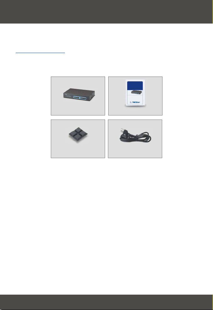
Unpacking
Open the shipping carton of the Switch and carefully unpack its contents. The
carton should contain the following items:
TEG-S80TXD
User’s Guide
Version 10.18.2005
Copyright ©2005. All Rights Reserved. TRENDnet.
TEG-S80TXD
User's Guide
Four rubber feet with
adhesive backing
AC power cord
If any item is found missing or damaged, please contact your local reseller for
replacement.
2
English
Page 5
Setup
The setup of the Switch can be performed using the following steps:
The surface must support at least 5 kg.
The power outlet should be within 1.82 meters (6 feet) of the device.
Visually inspect the power cord and see that it is secured fully to the AC
power connector.
Make sure that there is proper heat dissipation from and adequate
ventilation around the Switch. Do not place heavy objects on the Switch.
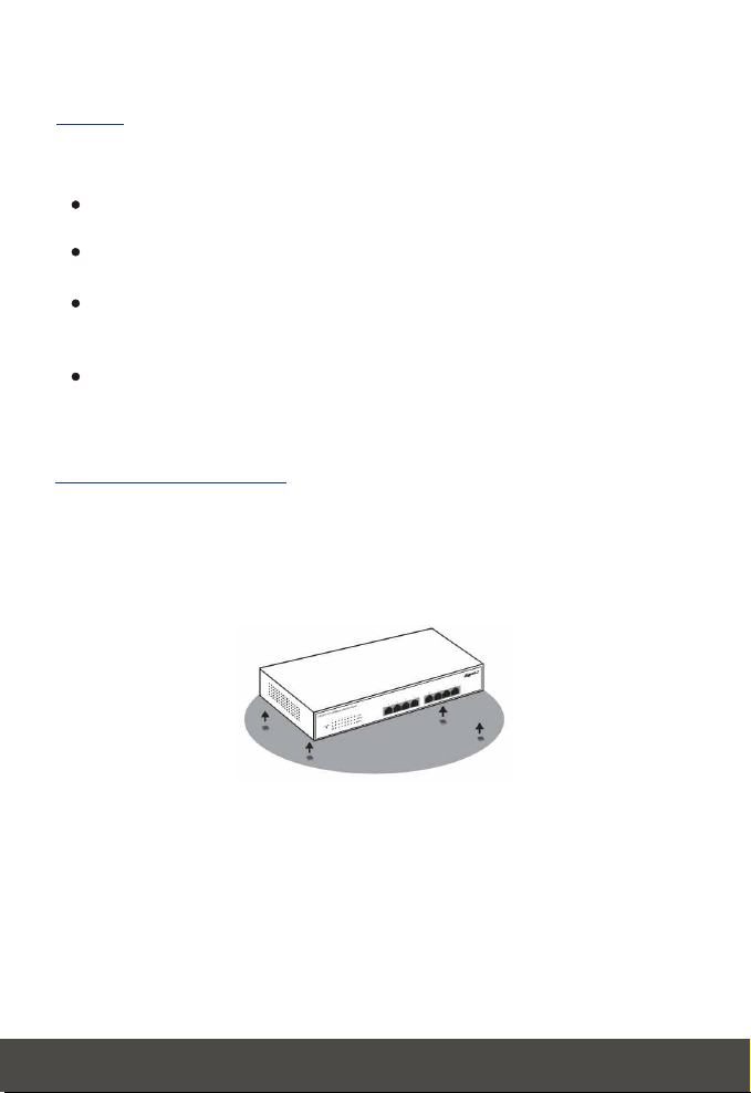
Desktop Installation
When installing the Switch on a desktop or shelf, the rubber feet included with
the device must be attached first. Attach these cushioning feet on the bottom at
each corner of the device. Allow enough ventilation space between the device
and the objects around it.
Gigabit Ethernet Switch installed on a Desktop or Shelf
3
English
Page 6
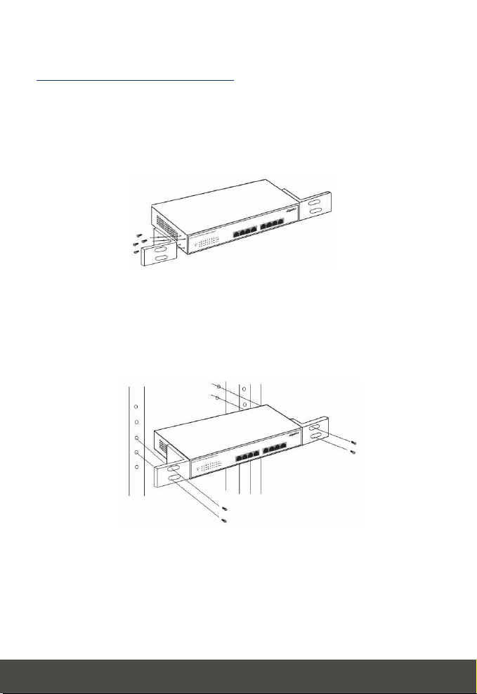
Rack Installation (optional)
The 8-Port 10/100/1000Mbps Gigabit Ethernet Switch can be mounted in an
EIA standard size, 19-inch rack, which can be placed in a wiring closet with
other equipment. To install, attach the mounting brackets on the Switch's front
panel (one on each side) and secure them with the provided screws.
Attaching the mounting brackets to the Switch
Then, use the screws provided with the equipment rack to mount the Switch in
the rack.
Installing the Switch on an equipment rack
4
English
Page 7

Connecting Network Cable
The 8-Port 10/100/1000Mbps Gigabit Ethernet Switch supports eight
10/100/1000Mbps Gigabit Ethernet ports. These ports support half or full
duplex mode when running in 10Mbps or 100Mbps. They support full duplex
while running in 1000Mbps.
These ports are Auto-MDIX type port. They can auto transform to MDI-II or
MDI-X medium type, so you can just make an connection with a straight or
crossover cable.
AC Power
The 8-port Gigabit Ethernet Switch can be used with 100~240V AC, 50~60 Hz
power source. The power supply of the Switch will adjust to the local power
specification automatically and may be turned on without having any or all LAN
segment cables connected.
5
English
Page 8

3. Identifying External Components
This chapter describes the front panel, rear panel and LED indicators of the
Switch
Front Panel
The front panel of the Switch consists of eight 1000BASE-T ports and LED
indicators.
Front panel view of the Switch
Eight Gigabit Ethernet ports of 10/100/1000Mbps Auto-Negotiation
interface.
Comprehensive LED indicators display the conditions of the Switch and
status of the network. A description of these LED indicators follows (see
LED Indicators).
Rear Panel
The rear panel of the Switch consists of an AC power connector. The following
figure shows the rear panel of the Switch.
Rear panel view of the Switch
AC Power Connector: This is a three-pronged connector that supports
the power cord. Plug in the female connector of the provided power cord
into this connector, and the male into a power outlet. Supported input
voltages range from 100~240V AC at 50~60 Hz.
6
English
Page 9

LED Indicators
The LED indicators of the Switch including Power, Link/Act, 1000Mbps and
100Mbps. The following shows the LED indicators for the Switch along with
explanation of each indicator.
The Switch LED indicators
Power:
This indicator lights green when the Switch is receiving power. It is off for
no power.
Link/ACT:
This LED indicator lights green when there is a valid connection (or link) to
the port. The LED indicator blinks whenever there is reception or
transmission (i.e. ActivityAct) of data at a port.
1000Mbps:
This LED indicator lights green when there is a valid 1000Mbps Gigabit
Ethernet connection (or link) to the port.
100Mbps:
This LED indicator lights green when there is a valid connection (or link) to
100Mbps Fast Ethernet device at the port.
If the connection (or link) is 10Mbps, both 1000Mbps and 100Mbps LED
indicators are off.
7
English
Page 10

Românǎ
1. Introducere
Aceasta sectiune descrie caracteristicile Switchului cu 8 porturi
10/100/1000Mbps Gigabit Ethernet
Trasaturi
Switchul cu 8 porturi 10/100/1000Mbps Gigabit Ethernet a fost realizat in
vederea unei instalari usoare si unei performante ridicate, intr-un mediu unde
traficul in retea si numarul utilizatorilor sunt intr-o continua.
8 porturi x 10/100/1000Mbps Auto-negociere Gigabit Ethernet
Auto-MDIX pentru fiecare port
Suporta mod de transfer Full/Half duplex pentru 10 si 100Mbps
Suporta mod de transfer Full duplex pentru 1000Mbps
Viteza la nivel de “fir” pentru receptare si transmitere
Metoda switching Store-and-Forward
Suporta intrari 8K table adrese absolute MAC
Supporta 256K Bytes RAM pentru buffering la informatie
LEDuri pentru diagnostic pe panpul frontal
Control al fluxului de tip IEEE 802.3x pentru full-duplex
Control al fluxului de presiune pentru half-duplex
Kit Rack optional pentru rack standard 19” .
8
Românǎ
Page 11
2. Despachetare si instalare
Acest capitol va puna la dispozitie informatii cu privire la despachetarea
Switchului si instalarea sa.
Despachetarea
Desfaceti cutia in care produsul a fost livrat si despachetati cu grija
componentele. Cutia respectiva trebuie sa contina urmatoarele:
TEG-S80TXD
User’s Guide
Version 10.18.2005
Copyright ©2005. All Rights Reserved. TRENDnet.
TEG-S80TXD
Acest ghid al utilizatorului
Patru picioare de cauciuc cu
partea din spate adeziva
Un cablu AC de alimentare
Daca unul din itemuri lipseste sau este avariat , va rugam sa contactati
vanzatorul in vederea inlocuirii produsului.
9
Românǎ
Page 12

Setup
Setupul Switchului poate fi dus la bun sfarsit folosind urmatorii pasi:
Suprafata trebuie sa suporte cel putin 5 Kg.
Priza trebuie sa se afle la o distanta de cel mult 1.82 metri de aparat.
sigurati-va ca respectivul cablu este bine atasat conectorului de
alimentare.
Asigurati-va ca exista posibilitatea unei dispersii cum se cuvine a caldurii
si o ventilatie adecvata in jurul Switchului. Nu asezati obiecte grele pe .
Instalarea Desktop
In momentul instalarii Switchului pe un sau pe un raft, picioarele din caucioc
livrate odata cu Switchul trebuiesc fixate mai inati.Atasati aceste picioare pe
partea de jos , in fiecare colt al Switchului. Permiteti indeajuns de mult spatiu
pentru ventilatie intre aparat si obiectele din jurul sau.
Switch Gigabit Ethernet instalat pe birou sau raft
10
Românǎ
Page 13

Instalare Rack (optional)
Switchul 10/100/1000Mbps Gigabit Ethernet cu 8 porturi poate fi montat la
marimea standard EIA a unui rack de 19 inci, ce poate fi asezat intr-un dulap
impreuna cu restul de fire si echipament. Pentru instalare, atasati clamele de
montare pe panoul frontal al Switchului ( cate una pe fiecare parte) si fixati-le
cu suruburile livrate odata cu produsul .
Atasarea clamelor de montare la Switch
Apoi, folositi suruburile respective pentru a monta Switchul in rack.
Instalarea Switchului in rack
11
Românǎ
Page 14

Conectarea Cablului de Retea
Switchul cu 8 porturi 10/100/1000Mbps Gigabit Ethernet suporta opt porturi
10/100/1000Mbps Gigabit Ethernet. Aceste porturi suporta moduri half
(jumatate) sau full duplex, la rularea la 10Mbps sau 100Mbps. Acestea suporta
full duplex la 1000Mbps.
Porturile sunt de tipul Auto-MDIX. Se pot transforma automat in tip mediu
MIDI-II sau MIDI-x, asadar puteti realize o conexiune cu un cablu fie direct, fie
incrucisat.
AC Power (Alimentare)
Acest Switch poate fi folosit la o sursa de alimentare 100~240V , 50~60 Hz .
Sursa de alimentare a Switchului se va ajusta automat la specificatiile locale
de energie si poate fi pornit in absenta conectarii vreunuia dintre .
12
Românǎ
Page 15

3. Identificarea componentelor externe
Acest capitol descrie panoul din spate si cel frontal, precum si LEDurile
impreuna cu indicatorii acestora.
Panoul Frontal
Panoul frontal consta in 8 porturi de tip 1000BASE-T LEDuri cu indicatori.
Vedere asupra panoului frontal al Switcului
Opt porturi Gigabit Ethernet de 10/100/1000Mbps interfata AutoNegociere.
Indicatori LED usor de inteles arata conditiile Switchului si statusul retelei.
O descrieie a acestor indicatori LED urmeaza. (vezi indicatori LED).
Panou Spate
Acest panou consta intr-un conector AC de alimentare. Figura de mai jos
ilustreaza acest lucru.
Panoul din spate al Switchului
Conector alimentare: Acesta este conectorul ce suporta cablul de
alimentare. Conectati cablul de alimentare in conector , iar capatul celalalt
conectati-l la o priza. Voltaj permis: 100~240V AC la 50~60 Hz.
13
Românǎ
Page 16

Indicatori LED
Indicatorii LED ai Switchului : Power, Link/Act, 1000Mbps si 100Mbps.
Urmatoarea imagine ilustreaza Indicatorii LED ai Switchului , impreuna cu
explicatiile pentru fiecare indicator.
Indicatorii LED ai Switchului
Power:
Acest indicator se aprinde de culoare verde cand Swichului receptioneaza
energie. Sta OFF cand nu este curent.
Link/ACT:
Acest indicator se aprinde de culoare verde cand exista o conexiune
valida.(sau link) la port. Indicatorul LED clipeste in cazul fiecarei receptii
sau transmisii (ActivityAct) de informatii la port.
1000Mbps:
Acest indicator LED se aprinde de culoarea verde cand exista o
conexiune (sau link) la port de tip 1000Mbps Gigabit Ethernet
100Mbps:
Acest indicator se aprinde de culoarea verde cand exista o conexiune
(sau link) port .
Daca conexiunea (sau linkul) este de 10Mbps, atat indicatorul de 1000Mbps
cat si cel de 100Mbps sunt oprite.
14
Românǎ
Page 17

Technical Specifications
General
IEEE 802.3ab 1000BASE-T
Standards:
IEEE 802.3u 100BASE-TX
IEEE 820.3 10BASE-T
Protocol:
Rata Transfer Date:
Topology:
Network Cables:
Number of Ports:
CSMA/CD
Ethernet: 10 Mbps (half-duplex), 20 Mbps
(full-duplex)
Fast Ethernet: 100 Mbps (half-duplex), 200 Mbps
(full-duplex)
Gigabit Ethernet: 2000 Mbps (full duplex)
Star
Ethernet: 2-pair UTP/STP Cat. 3,4,5 Cable
Fast Ethernet: 2-pair UTP/STP Cat. 5 Cable
Gigabit Ethernet: 4-pair UTP/STP Cat. 5 Cable
Eight(8) 10/100/1000Mbps Auto-Negotiation and
Auto-MDIX ports
15
Page 18

Physical and Environmental
DC inputs:
Power Consumption:
Operating Temperature:
Storage Temperature:
Humidity:
Dimensions:
Weight:
EMI:
Safety:
Transmission Method:
RAM Buffer:
Filtering Address Table:
Packet Filtering/
Forwarding Rate:
100 ~ 240V AC Universal, 50/60 Hz
20 watts maximum
0° ~ 40° C
-10°C ~ 55°C
5% ~ 95% RH, non-condensing
280(W) × 180(D) × 44(H) mm
1.62Kg
FCC Class A, CE Mark Class A, VCCI Class A
cUL, TUV/GS
Performance
Store-and-forward
256K Bytes per device
8K MAC address per device
10Mbps Ethernet: 14,880 pps
100Mbps Fast Ethernet: 148,800 pps
1000Mbps Gigabit Ethernet: 1,488,000 pps
MAC Address Learning:
Self-learning, auto-aging
16
Page 19

FCC Warning
This equipment has been tested and found to comply with the regulations for a Class A
digital device, pursuant to Part 15 of the FCC Rules. These limits are designed to
provide reasonable protection against harmful interference when the equipment is
operated in a commercial environment. This equipment generates, uses, and can
radiate radio frequency energy and, if not installed and used in accordance with this
user's guide, may cause harmful interference to radio communications. Operation of this
equipment in a residential area is likely to cause harmful interference, in which case the
user will be required to correct the interference at his own expense.
CE Mark Warning
This is a Class A product. In a domestic environment, this product may cause radio
interference, in which case the user may be required to take adequate measures.
VCCI Warning
This is a product of VCCI Class A Compliance.
Certifications
This equipment has been tested and found to comply with FCC and CE Rules.
Operation is subject to the following two conditions:
(1) This device may not cause harmful interference.
(2) This device must accept any interference received.
Including interference that may cause undesired operation.
NOTE: THE MANUFACTURER IS NOT RESPONSIBLE FOR ANY RADIO OR TV
INTERFERENCE CAUSED BY UNAUTHORIZED MODIFICATIONS TO THIS
EQUIPMENT. SUCH MODIFICATIONS COULD VOID THE USER’S AUTHORITY TO
OPERATE THE EQUIPMENT.
17
Page 20

Limited Warranty
TRENDware warrants its products against defects in material and
workmanship, under normal use and service, for the following lengths of
time from the date of purchase.
Wired Products - 5 Years Warranty
If a product does not operate as warranted above during the applicable
warranty period, TRENDware shall, at its option and expense, repair the
defective product or part, deliver to customer an equivalent product or
part to replace the defective item, or refund to customer the purchase
price paid for the defective product. All products that are replaced will
become the property of TRENDware. Replacement products may be
new or reconditioned.
TRENDware shall not be responsible for any software, firmware,
information, or memory data of customer contained in, stored on, or
integrated with any products returned to TRENDware pursuant to any
warranty.
There are no user serviceable parts inside the product. Do not remove
or attempt to service the product by any unauthorized service center.
This warranty is voided if (i) the product has been modified or repaired
by any unauthorized service center, (ii) the product was subject to
accident, abuse, or improper use (iii) the product was subject to
conditions more severe than those specified in the manual.
Warranty service may be obtained by contacting TRENDware office
within the applicable warranty period for a Return Material Authorization
(RMA) number, accompanied by a copy of the dated proof of the
purchase. Products returned to TRENDware must be pre-authorized by
TRENDware with RMA number marked on the outside of the package,
and sent prepaid, insured and packaged appropriately for safe
shipment.
18
Page 21

WARRANTIES EXCLUSIVE: IF THE TRENDWARE PRODUCT DOES
NOT OPERATE AS WARRANTED ABOVE, THE CUSTOMER'S SOLE
REMEDY SHALL BE, AT TRENDWARE'S OPTION, REPAIR OR
REPLACEMENT. THE FOREGOING WARRANTIES AND REMEDIES
ARE EXCLUSIVE AND ARE IN LIEU OF ALL OTHER WARRANTIES,
EXPRESSED OR IMPLIED, EITHER IN FACT OR BY OPERATION OF
LAW, STATUTORY OR OTHERWISE, INCLUDING WARRANTIES OF
MERCHANTABILITY AND FITNESS FOR A PARTICULAR PURPOSE.
TRENDWARE NEITHER ASSUMES NOR AUTHORIZES ANY OTHER
PERSON TO ASSUME FOR IT ANY OTHER LIABILITY IN
CONNECTION WITH THE SALE, INSTALLATION MAINTENANCE OR
USE OF TRENDWARE'S PRODUCTS.
TRENDWARE SHALL NOT BE LIABLE UNDER THIS WARRANTY IF ITS
TESTING AND EXAMINATION DISCLOSE THAT THE ALLEGED
DEFECT IN THE PRODUCT DOES NOT EXIST OR WAS CAUSED BY
CUSTOMER'S OR ANY THIRD PERSON'S MISUSE, NEGLECT,
IMPROPER INSTALLATION OR TESTING, UNAUTHORIZED
ATTEMPTS TO REPAIR OR MODIFY, OR ANY OTHER CAUSE
BEYOND THE RANGE OF THE INTENDED USE, OR BY ACCIDENT,
FIRE, LIGHTNING, OR OTHER HAZARD.
LIMITATION OF LIABILITY: TO THE FULL EXTENT ALLOWED BY LAW
TRENDWARE ALSO EXCLUDES FOR ITSELF AND ITS SUPPLIERS
ANY LIABILITY, WHETHER BASED IN CONTRACT OR TORT
(INCLUDING NEGLIGENCE), FOR INCIDENTAL, CONSEQUENTIAL,
INDIRECT, SPECIAL, OR PUNITIVE DAMAGES OF ANY KIND, OR FOR
LOSS OF REVENUE OR PROFITS, LOSS OF BUSINESS, LOSS OF
INFORMATION OR DATE, OR OTHER FINANCIAL LOSS ARISING OUT
OF OR IN CONNECTION WITH THE SALE, INSTALLATION,
MAINTENANCE, USE, PERFORMANCE, FAILURE, OR INTERRUPTION
OF THE POSSIBILITY OF SUCH DAMAGES, AND LIMITS ITS LIABILITY
TO REPAIR, REPLACEMENT, OR REFUND OF THE PURCHASE PRICE
PAID, AT TRENDWARE'S OPTION. THIS DISCLAIMER OF LIABILITY
FOR DAMAGES WILL NOT BE AFFECTED IF ANY REMEDY
PROVIDED HEREIN SHALL FAIL OF ITS ESSENTIAL PURPOSE.
Governing Law: This Limited Warranty shall be governed by the laws of
the state of California.
AC/DC Power Adapter, Cooling Fan, and Power Supply carry a 1 Year
Warranty
19
Page 22

@
Product Warranty Registration
Please take a moment to register your product online.
Go to TRENDnet’s website at http://www.TRENDNET.com
TRENDnet Technical Support
US/Canada Support Center European Support Center
Contact Contact
Telephone:
Fax:
Email:
Tech Support Hours
7:30am - 6:00pm Pacific Standard Time
Monday - Friday
1(888) 777-1550
1(310) 626-6267
support@trendnet.com
TRENDnet
3135 Kashiwa Street. Torrance, CA 90505
Telephone
Deutsch : +49 (0) 6331 / 268-460
Français : +49 (0) 6331 / 268-461
Español : +49 (0) 6331 / 268-462
English : +49 (0) 6331 / 268-463
Italiano : +49 (0) 6331 / 268-464
Dutch : +49 (0) 6331 / 268-465
Eesti : +372-6593613 (9.00AM to 5:00PM)
Fax:
Tech Support Hours
8:00am - 6:00pm Middle European Time
Monday - Friday
http://www.trendnet.com
Copyright ©2005. All Rights Reserved. TRENDnet.
0800-907-161 (numéro vert)
+49 (0) 6331 / 268-466
 Loading...