

Page 1
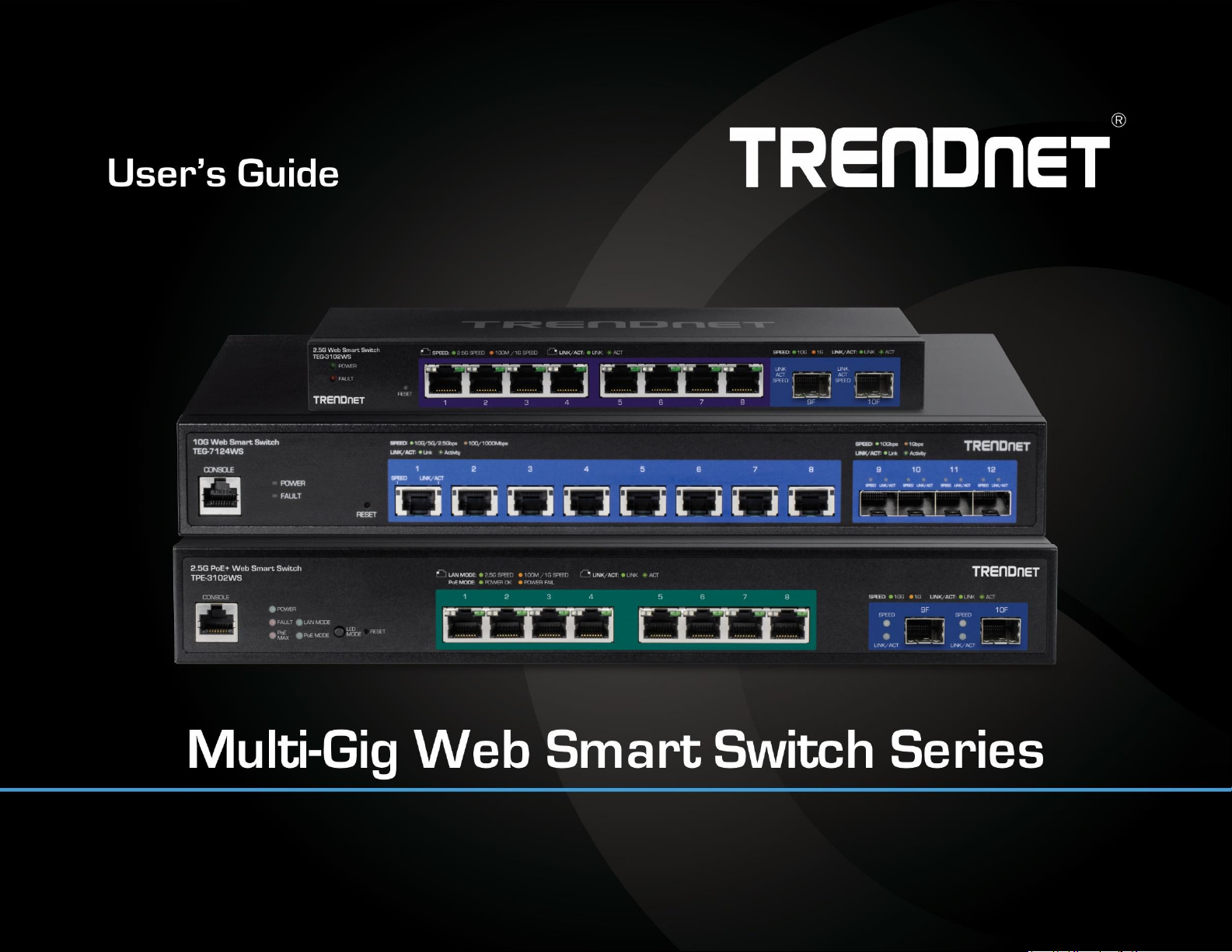
TRENDnet User’s Guide
Cover Page
Page 2

© Copyright 2022 TRENDnet. All Rights Reserved.
TRENDnet User’s Guide
Table of Contents
a
Thank you for purchasing your new TRENDnet Multi-Gig Web Smart Switch!
Please note: The scope of this user's guide encompasses multiple
products with varying features. Images, artwork, and other specificities
including port count, interfaces etc. may not be identical to the model
you purchased. Please consult the specific model specifications for your
unit for a full list of supported features.
PoE Web Smart Switch Series Product Overview .............................. i
TEG-3102WS Overview .................................................................................................... i
TPE-3102WS Overview .................................................................................................. iii
TPE-3524S / TPE-3524SF Overview ................................................................................ v
TEG-7124WS Overview ................................................................................................ viii
TEG-3524S Overview ..................................................................................................... 1
Switch Installation .......................................................................... 3
Desktop Hardware Installation ...................................................................................... 3
Rack Mount Hardware Installation ................................................................................ 3
Setup Wizard ................................................................................................................. 4
Basic IP Configuration .................................................................................................... 7
Connect additional devices to your switch .................................................................... 9
Access your switch management page........................................................................ 10
Dashboard ................................................................................................................... 10
View your switch status information ............................................................................... 10
Real-time Statistics ...................................................................................................... 12
View your switch status information ............................................................................... 12
System .......................................................................................... 12
System Settings ........................................................................................................... 12
Set your system information............................................................................................ 12
L3 Feature .................................................................................................................... 14
IPv4 Interface ................................................................................................................... 14
IPv4 ARP Aging Time ........................................................................................................ 15
IPv4 Static ARP ................................................................................................................. 15
System Time ..................................................................................................................... 16
SNMP ........................................................................................... 17
Global Settings ................................................................................................................. 17
User List ........................................................................................................................... 17
Page 3

© Copyright 2022 TRENDnet. All Rights Reserved.
TRENDnet User’s Guide
Table of Contents
b
Community List ................................................................................................................ 18
Group List ......................................................................................................................... 18
Access List ........................................................................................................................ 18
View List ........................................................................................................................... 19
RMON .......................................................................................................................... 19
Statistics ........................................................................................................................... 19
Event List .......................................................................................................................... 20
Event Log Table ................................................................................................................ 21
Alarm List ......................................................................................................................... 21
History .............................................................................................................................. 22
History Log Table .............................................................................................................. 23
MAC Address Table ...................................................................................................... 23
Static MAC Address .......................................................................................................... 23
Dynamic MAC Address ..................................................................................................... 24
MAC Aging Time ............................................................................................................... 24
SFP Module Information .............................................................................................. 24
Module & DDM ................................................................................................................ 24
IEEE 802.3az EEE .......................................................................................................... 25
Enable IEEE 802.3az Power Saving Mode ........................................................................ 25
Network........................................................................................ 26
Physical Interface ......................................................................................................... 26
Configure Physical Interfaces ........................................................................................... 26
Port Isolation .................................................................................................................... 27
Mirroring .......................................................................................................................... 27
Jumbo Frames .................................................................................................................. 28
VLAN Settings .............................................................................................................. 29
802.1Q VLAN .................................................................................................................... 29
PVID & Ingress Filter ........................................................................................................ 30
GVRP ............................................................................................................................ 31
Protocol ............................................................................................................................ 31
Port Settings ..................................................................................................................... 31
Spanning Tree .............................................................................................................. 32
Protocol ............................................................................................................................ 32
Root Bridge Information .................................................................................................. 33
RSTP Port Settings ............................................................................................................ 33
CIST Port Settings ............................................................................................................. 34
MST .................................................................................................................................. 35
MST Port Settings ............................................................................................................. 36
Trunk ............................................................................................................................ 37
Settings ............................................................................................................................ 37
LACP ................................................................................................................................. 37
LACP Timeout ................................................................................................................... 38
IGMP Snooping ............................................................................................................ 38
Global Settings ................................................................................................................. 38
Fast Leave ........................................................................................................................ 38
VLAN Settings ................................................................................................................... 39
Querier Settings ............................................................................................................... 39
Router Settings ................................................................................................................ 40
MLD Snooping ............................................................................................................. 40
Global Settings ................................................................................................................. 40
Fast Leave ........................................................................................................................ 40
VLAN Settings ................................................................................................................... 41
Querier Settings ............................................................................................................... 41
Router Settings ................................................................................................................ 41
Loopback Detection ..................................................................................................... 42
Global Settings ................................................................................................................. 42
Voice VLAN .................................................................................................................. 42
Global Settings ................................................................................................................. 43
OUI Settings ..................................................................................................................... 44
Port Settings ..................................................................................................................... 44
LLDP ............................................................................................................................. 45
Enable and configure LLDP .............................................................................................. 45
Settings ............................................................................................................................ 45
Page 4

© Copyright 2022 TRENDnet. All Rights Reserved.
TRENDnet User’s Guide
Table of Contents
c
Multicast Filtering ........................................................................................................ 46
Enable Multicast Filtering ................................................................................................ 46
Administration ............................................................................................................. 46
Changing login credentials ............................................................................................... 46
Logs .............................................................................................................................. 47
Settings............................................................................................................................. 47
Remote Logging ............................................................................................................... 47
Log Table .......................................................................................................................... 47
QoS (Quality of Service) ................................................................ 47
Global Settings ............................................................................................................. 48
Set QoS settings ............................................................................................................... 48
CoS ............................................................................................................................... 48
Set CoS priority settings ................................................................................................... 48
DSCP Mapping ............................................................................................................. 49
Set DSCP (Differentiated Services Code Point) Class Mapping settings ........................... 49
Port CoS ....................................................................................................................... 50
Set Port Priority ................................................................................................................ 50
Bandwidth Control ....................................................................................................... 50
Bandwidth Control ........................................................................................................... 50
Storm Control ................................................................................................................... 51
PoE (Power over Ethernet) ............................................................ 52
Power over Ethernet.................................................................................................... 52
Configure PoE Budget ...................................................................................................... 53
Configure PoE Port Settings ............................................................................................. 53
Flick Reboot ...................................................................................................................... 54
Time Range .................................................................................................................. 54
Configure PoE Time Range ............................................................................................... 54
PD Lifeguard................................................................................................................. 55
Configure PD Alive Check ................................................................................................. 55
Advanced Configuration .................................................................................................. 55
Security ........................................................................................ 56
802.1X Authentication ................................................................................................. 56
Set 802.1X ........................................................................................................................ 56
Timeout ............................................................................................................................ 56
CLI Timeout ...................................................................................................................... 56
Port Security..................................................................................................................... 57
Access Control: Creating MAC ACL .................................................................................. 57
Access Control: Configuring MAC ACL ............................................................................. 57
Access Control: Creating IPv4 ACL ................................................................................... 58
Access Control: Configuring IPv4 ACL .............................................................................. 58
Access Control: Creating IPv6 ACL ................................................................................... 59
Access Control: Configuring IPv6 ACL .............................................................................. 59
Port Binding ..................................................................................................................... 60
Dial-in User .................................................................................................................. 60
Create Dial-In Users (Local Authentication Method) ....................................................... 60
RADIUS ......................................................................................................................... 61
Add Radius Servers (RADIUS Authentication Method) .................................................... 61
TACACS+ ...................................................................................................................... 61
Add TACACS+ Servers (TACACS+ Authentication Method) .............................................. 61
DHCP Snooping ............................................................................................................ 63
Settings ............................................................................................................................ 63
VLAN ................................................................................................................................ 63
Trusted Port Interfaces .................................................................................................... 64
Denial of Service .......................................................................................................... 64
Denial of Service (DoS) ..................................................................................................... 64
Tools............................................................................................. 65
Firmware Upgrade ....................................................................................................... 65
Upgrade your switch’s firmware ...................................................................................... 65
Firmware Upgrade via HTTP Settings ............................................................................... 66
Page 5

© Copyright 2022 TRENDnet. All Rights Reserved.
TRENDnet User’s Guide
Table of Contents
d
Firmware Upgrade via TFTP Settings ............................................................................... 66
Dual Image ....................................................................................................................... 66
Config Backup Restore ................................................................................................. 67
Config Backup/Restore .................................................................................................... 67
Backup/Restore via HTTP Settings ................................................................................... 67
Backup/Restore via TFTP Settings .................................................................................... 68
Diagnostics ................................................................................................................... 69
Cable Diagnostics Test ..................................................................................................... 69
Ping Test ...................................................................................................................... 69
Network Connectivity Test (Ping Tool) ............................................................................. 69
IPv6 Ping Test ............................................................................................................... 70
Network Connectivity Test (Ping Tool) ............................................................................. 70
Trace Route .................................................................................................................. 71
Reboot ......................................................................................................................... 71
Reboot/Reset to factory defaults ..................................................................................... 71
Command Line Interface Reference ............................................... 73
Access your switch command line interface ............................................................... 73
Switch CLI User Manual ................................................................. 76
System ......................................................................................................................... 76
Hardware Features and Specifications ......................................... 162
Web Smart Switch Series Software Specifications ........................ 164
Quick Installation Guide Troubleshooting .................................... 167
Page 6
© Copyright 2022 TRENDnet. All Rights Reserved.
i
TRENDnet User’s Guide
Multi-Gig Web Smart Switch Series
PoE Web Smart Switch Series Product Overview
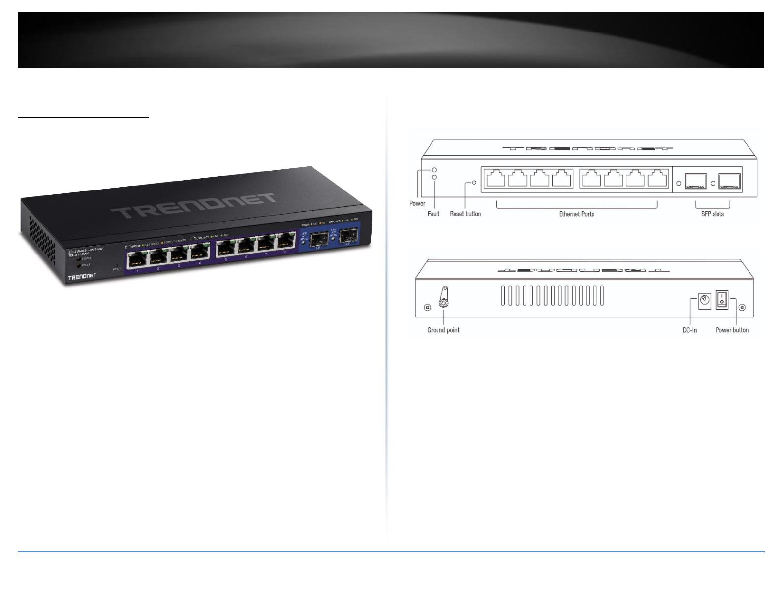
TEG-3102WS Overview
TEG-3102WS
Package Contents
In addition to your switch, the package includes:
• Quick Installation Guide
• Power adapter (12V DC, 1.5A)
If any package contents are missing or damaged, please contact the retail store, online
retailer, or reseller/distributor from which the product was purchased.
TPE-3102WS Hardware Features
Front View
Rear View
• Power and Fault LED – LED indicators for power and fault.
• Reset Button – Press and hold the button 1~3 seconds and release to reboot
the device. Pressing the button more than 5 seconds will reset the switch to
factory defaults. The ports LEDs will turn off to indicate that the reset was
initiated.
• Ethernet Ports (1-8) – Connect network devices at 2.5Gbps / 1Gbps / 100Mbps
speed.
• SFP Slots (9-10) – Supports optional 10Gbps or 1Gbps mini-GBIC SFP modules
for uplink or downlink connections.
• Ground Point – Switch can be grounded from this point
• DC-In – Switch can be powered on from the power adapter here
Page 7
© Copyright 2022 TRENDnet. All Rights Reserved.
ii
TRENDnet User’s Guide
Multi-Gig Web Smart Switch Series
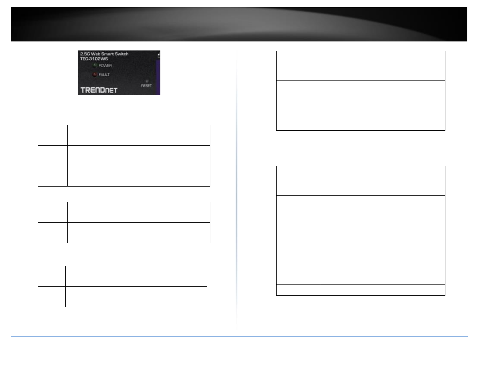
Diagnostic LEDs
Power LED
On
:
When the Power LED is on, the device is receiving
power.
Off
:
When the Power LED is off, the power adapter is
not connected or the device is not receiving power.
Blinking
:
When the Power LED is blinking, the switch is
receiving power and is botting up
Fault LED
Amber
On
:
When the Fault LED is on, there is an error with the
switch.
Off
:
When the Fault LED is off, there is no error with the
switch.
Ethernet Port LEDs (1-8)
Green
on
:
When the Green LED is on, the respective port is
connected to a 2.5Gbps Ethernet network.
Amber
on
:
When the Green LED lights on, the respective port
is connected to a 100/1000Mbps Ethernet network.
Green
Blinking
:
When the LED is blinking green, the port is
transmitting or receiving data on the network at
2.5Gbps speed.
Amber
Blinking
:
When the LED is blinking amber, the port is
transmitting or receiving data on the network at
100/1000Mbps speed.
Off
When the LED is off, the respective port is
disconnected.
SFP Slots (9-10)
Link/Activity
Green on
:
When the SFP LED is on, the link established
using the SFP module is operating at 10Gbps
speed.
Green
blinking
:
When the SFP LED is blinking, the port is
transmitting or receiving data on through the
10Gbps link established.
Amber on
:
When the SFP LED is on, the link established
using the SFP module is operating at
1000Mbps speed.
Amber
blinking
:
When the SFP LED is blinking, the port is
transmitting or receiving data on through the
1000Mbps link established.
Off : No link established.
Page 8
© Copyright 2022 TRENDnet. All Rights Reserved.
iii
TRENDnet User’s Guide
Multi-Gig Web Smart Switch Series
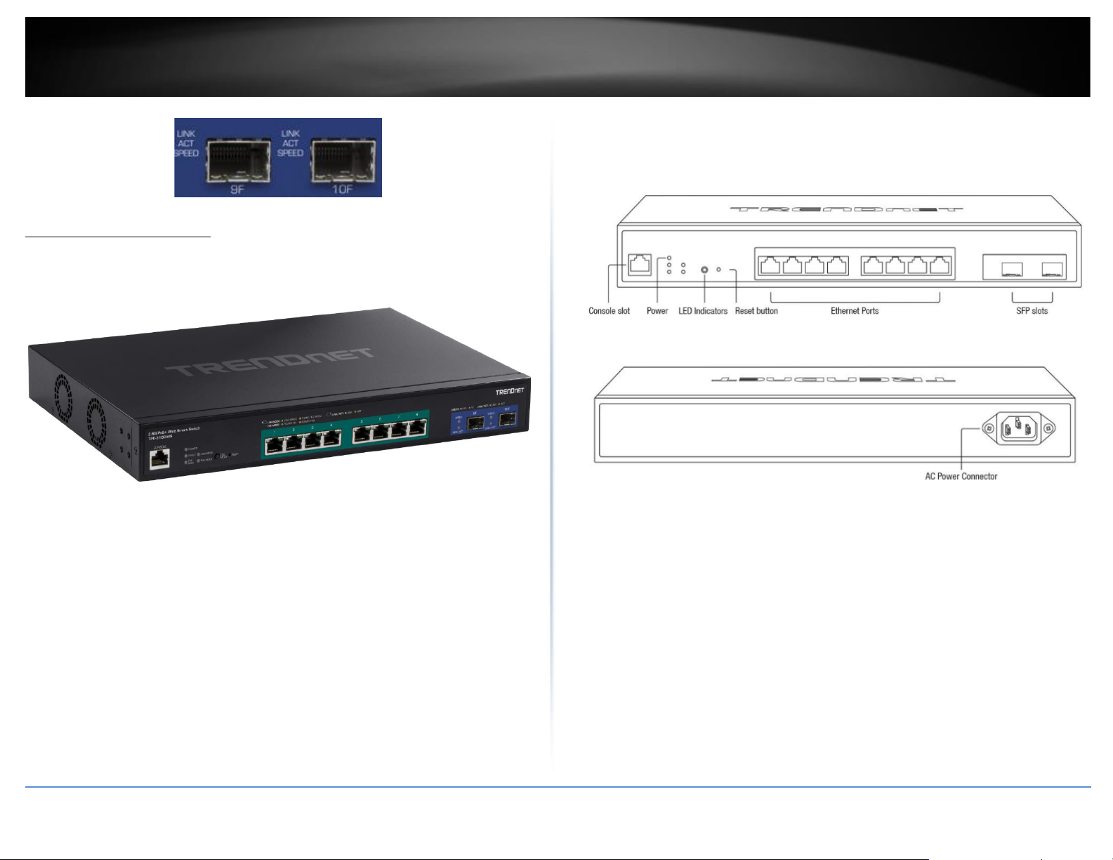
TPE-3102WS Overview
TPE-3102WS
Package Contents
In addition to your switch, the package includes:
• Quick Installation Guide
• Power Cord (1.8m / 6 ft.)
• Rack mount kit
If any package contents are missing or damaged, please contact the retail store, online
retailer, or reseller/distributor from which the product was purchased.
TPE-3102WS Hardware Features
Front View
Rear View
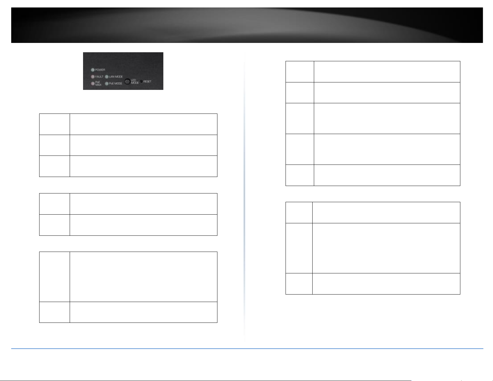
• Power & LED indicators – Displays switch activities
• LED Mode – Switches the LED indicators between PoE mode and Link/Activity
mode.
• Reset Button – Press and hold the button 1~3 seconds and release to reboot
the device. Pressing the button more than 5 seconds will reset the switch to
factory defaults. The ports LEDs will turn off to indicate that the reset was
initiated.
• Mode Button – Press the mode button to change LED indicators to display
Link/Activity Mode, or PoE Mode.
• Ethernet Ports (1-8) – Connect either network PoE+ or non-PoE devices at
2.5Gbps / 1Gbps / 100Mbps speeds.
• SFP Slots (9-10) – Supports optional 10Gbps or 1Gbps mini-GBIC SFP modules
for uplink or downlink connections.
Page 9
© Copyright 2022 TRENDnet. All Rights Reserved.
iv
TRENDnet User’s Guide
Multi-Gig Web Smart Switch Series
Diagnostic LEDs
Power LED
On
:
When the Power LED is on, the device is receiving
power.
Off
:
When the Power LED is off, the power adapter is
not connected or the device is not receiving power.
Blinking
:
When the Power LED is blinking, the switch is
receiving power and is botting up
Fault LED
Amber
On
:
When the Fault LED is on, there is an error with the
switch.
Off
:
When the Fault LED is off, there is no error with the
switch.
PoE MAX (Power over Ethernet Max.)
Amber
On
:
When reaching near the max PoE power budget
provided 240W or above, the LED will turn on and
the system will not provide power additional PD
(PoE client devices) after max PoE budget is
reached.
Off
:
When the PoE power provided is below the 240W
PoE power budget.
Gigabit Ethernet PoE+ Port LEDs (1-8)
Green
on
:
When the Green LED is on, the respective port is
connected to a 2.5Gbps Ethernet network.
Amber
on
:
When the Green LED lights on, the respective port
is connected to a 100/1000Mbps Ethernet network.
Green
Blinking
:
When the LED is blinking green, the port is
transmitting or receiving data on the network at
2.5Gbps speed.
Amber
Blinking
:
When the LED is blinking amber, the port is
transmitting or receiving data on the network at
100/1000Mbps speed.
Off
When the LED is off, the respective port is
disconnected.
Gigabit Ethernet Port PoE+ LEDs (1-8)
Green
on
:
When the Green LED is on, the connected device is
receiving power.
Amber
on
:
When the Amber LED lights on, the connected PoE
device is not receiving power. The cause is either
insufficient power budget, or due to
Class/PowerLimit restrictions in the PoE
configurations.
Off
:
When the LED is off, the respective port is either not
connected to a PoE device or is disconnected.
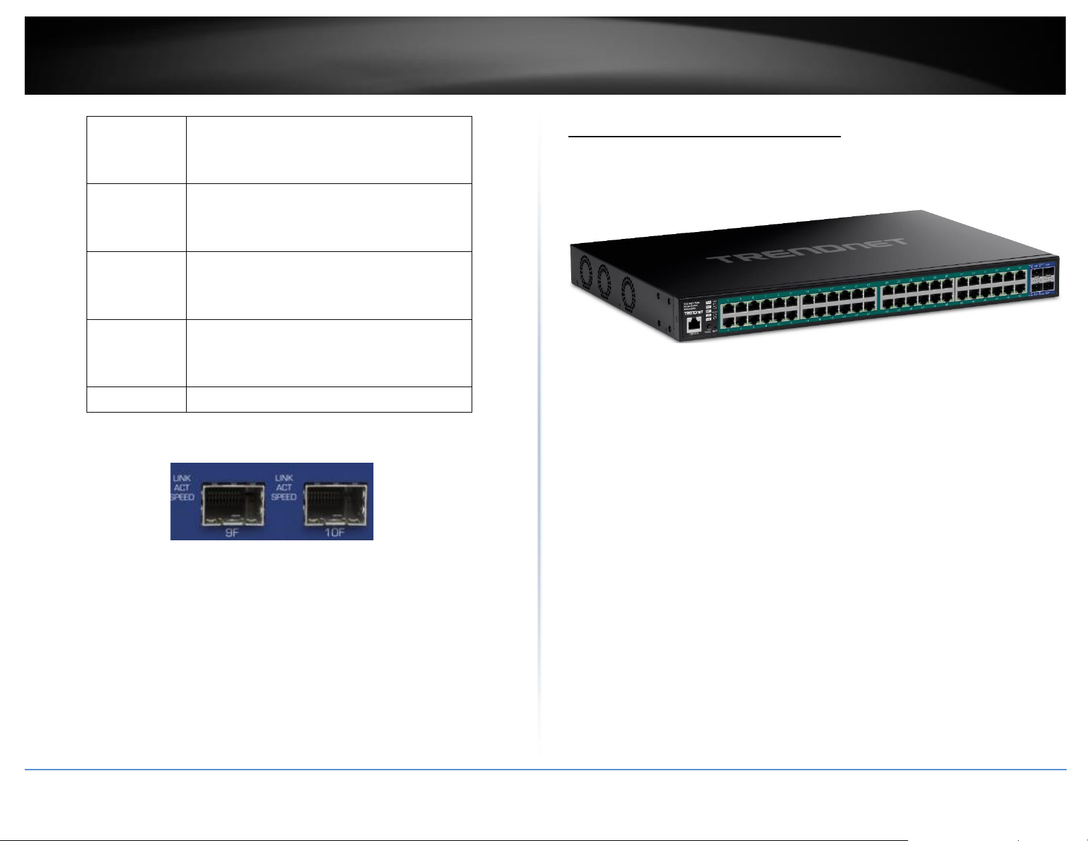
SFP Slots (9-10)
Page 10
© Copyright 2022 TRENDnet. All Rights Reserved.
v
TRENDnet User’s Guide
Multi-Gig Web Smart Switch Series
Green on
:
When the SFP LED is on, the link established
using the SFP module is operating at 10Gbps
speed.
Green
blinking
:
When the SFP LED is blinking, the port is
transmitting or receiving data on through the
10Gbps link established.
Amber on
When the SFP LED is on, the link established
using the SFP module is operating at
1000Mbps speed.
Amber
blinking
When the SFP LED is blinking, the port is
transmitting or receiving data on through the
1000Mbps link established.
Off No link established.
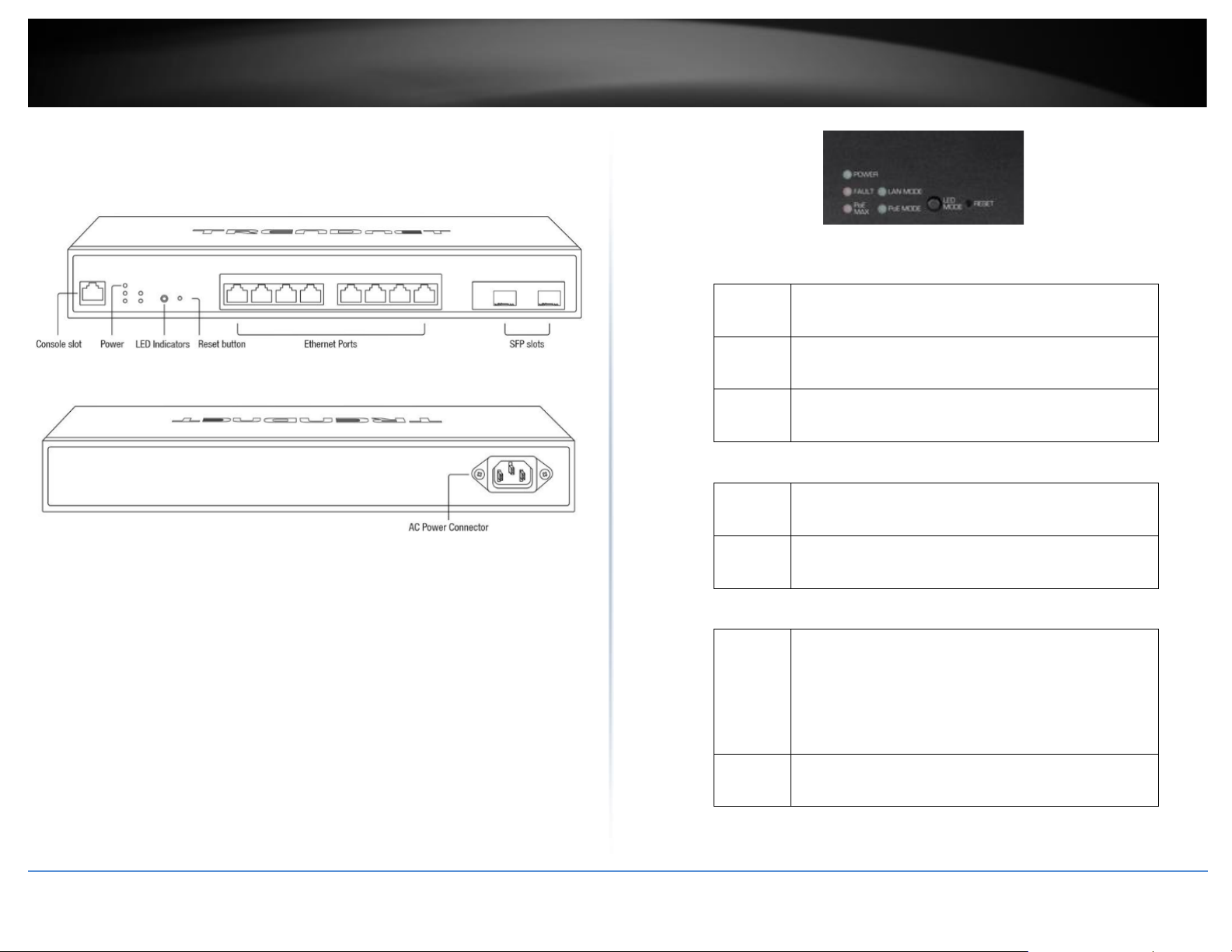
TPE-3524S / TPE-3524SF Overview
TPE-3524S / TPE-3524SF
Package Contents
In addition to your switch, the package includes:
• Quick Installation Guide
• Power Cord (1.8m / 6 ft.)
• Rack mount kit
If any package contents are missing or damaged, please contact the retail store, online
retailer, or reseller/distributor from which the product was purchased.
Page 11
© Copyright 2022 TRENDnet. All Rights Reserved.
vi
TRENDnet User’s Guide
Multi-Gig Web Smart Switch Series
TPE-3524S / TPE-3524SF Hardware Features
Front View
Rear View
• Power & LED indicators – Displays switch activities
• LED Mode – Switches the LED indicators between PoE mode and Link/Activity
mode.
• Reset Button – Press and hold the button 1~3 seconds and release to reboot
the device. Pressing the button more than 5 seconds will reset the switch to
factory defaults. The ports LEDs will turn off to indicate that the reset was
initiated.
• Mode Button – Press the mode button to change LED indicators to display
Link/Activity Mode, or PoE Mode.
• Ethernet Ports (1-8) – Connect either network PoE+ or non-PoE devices at
2.5Gbps / 1Gbps / 100Mbps speeds.
• SFP Slots (9-10) – Supports optional 10Gbps or 1Gbps mini-GBIC SFP modules
for uplink or downlink connections.
Diagnostic LEDs
Power LED
On
:
When the Power LED is on, the device is receiving
power.
Off
:
When the Power LED is off, the power adapter is
not connected or the device is not receiving power.
Blinking
:
When the Power LED is blinking, the switch is
receiving power and is botting up
Fault LED
Amber
On
:
When the Fault LED is on, there is an error with the
switch.
Off
:
When the Fault LED is off, there is no error with the
switch.
PoE MAX (Power over Ethernet Max.)
Amber
On
:
When reaching near the max PoE power budget
provided 240W or above, the LED will turn on and
the system will not provide power additional PD
(PoE client devices) after max PoE budget is
reached.
Off
:
When the PoE power provided is below the 240W
PoE power budget.
Page 12
© Copyright 2022 TRENDnet. All Rights Reserved.
vii
TRENDnet User’s Guide
Multi-Gig Web Smart Switch Series
Gigabit Ethernet PoE+ Port LEDs (1-8)
Green
on
:
When the Green LED is on, the respective port is
connected to a 2.5Gbps Ethernet network.
Amber
on
:
When the Green LED lights on, the respective port
is connected to a 100/1000Mbps Ethernet network.
Green
Blinking
:
When the LED is blinking green, the port is
transmitting or receiving data on the network at
2.5Gbps speed.
Amber
Blinking
:
When the LED is blinking amber, the port is
transmitting or receiving data on the network at
100/1000Mbps speed.
Off
When the LED is off, the respective port is
disconnected.
Gigabit Ethernet Port PoE+ LEDs (1-48)
Green
on
:
When the Green LED is on, the connected device is
receiving power.
Amber
on
:
When the Amber LED lights on, the connected PoE
device is not receiving power. The cause is either
insufficient power budget, or due to
Class/PowerLimit restrictions in the PoE
configurations.
Off
:
When the LED is off, the respective port is either not
connected to a PoE device or is disconnected.
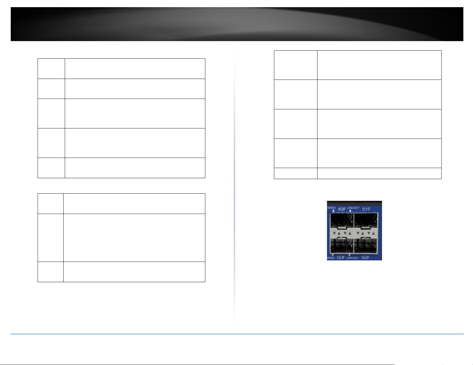
SFP Slots (49-52)
Green on
:
When the SFP LED is on, the link established
using the SFP module is operating at 10Gbps
speed.
Green
blinking
:
When the SFP LED is blinking, the port is
transmitting or receiving data on through the
10Gbps link established.
Amber on
When the SFP LED is on, the link established
using the SFP module is operating at
1000Mbps speed.
Amber
blinking
When the SFP LED is blinking, the port is
transmitting or receiving data on through the
1000Mbps link established.
Off No link established.
Page 13
© Copyright 2022 TRENDnet. All Rights Reserved.
viii
TRENDnet User’s Guide
Multi-Gig Web Smart Switch Series
TEG-7124WS Overview
Package Contents
In addition to your switch, the package includes:
• Quick Installation Guide
• Power cord (1.8 m / 6 ft.)
• Rack mount kit
If any package contents are missing or damaged, please contact the retail store, online
retailer, or reseller/distributor from which the product was purchased.
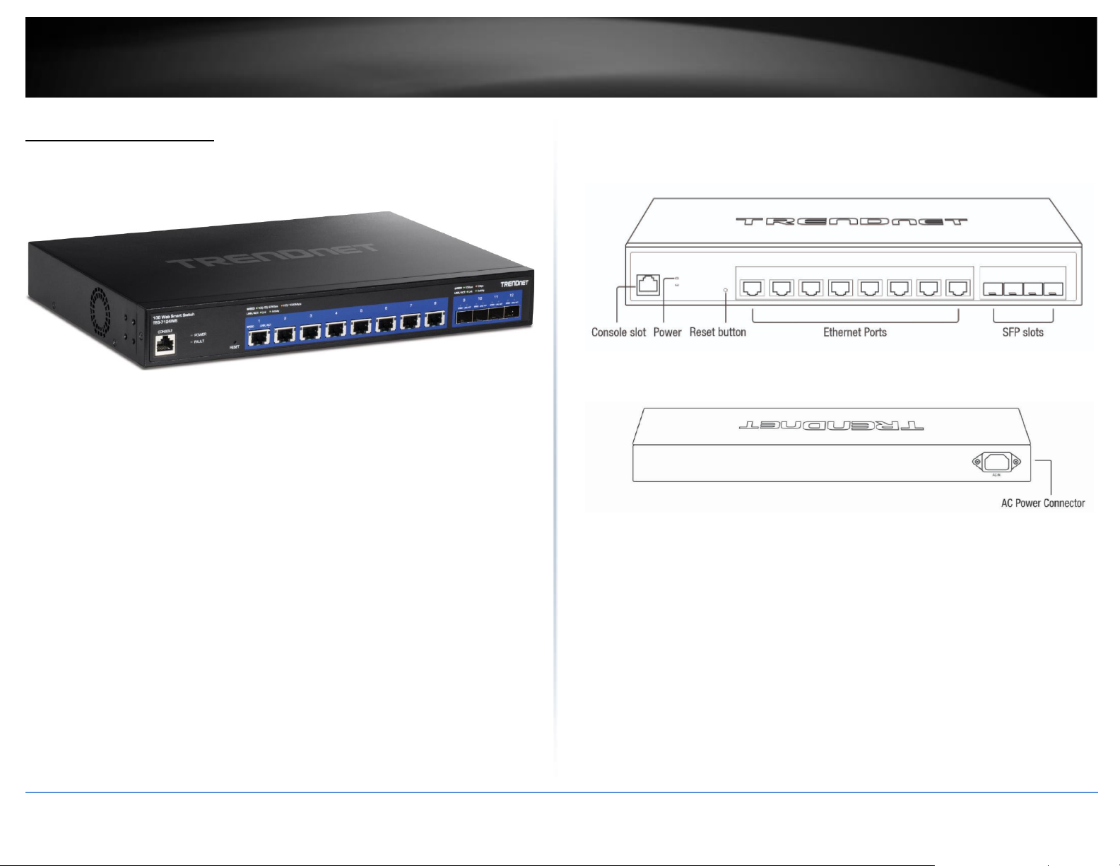
TEG-7124WS Hardware Features
Front View
Rear View
• Power LED Indicator – LED indicators for power and fault
• Reset Button – Press and hold the button 1~3 seconds and release to reboot
the device. Pressing the button more than 5 seconds will reset the switch to
factory defaults. The ports LEDs will turn off to indicate that the reset was
initiated.
• Ethernet Ports (1-8) – Connect network devices at 10Gbps / 5Gbps 2.5Gbps /
1Gbps / 100Mbps speeds.
• SFP Slots (9-12) – Supports optional 10Gbps or 1Gbps mini-GBIC SFP modules
for uplink or downlink connections.
Page 14
© Copyright 2022 TRENDnet. All Rights Reserved.
ix
TRENDnet User’s Guide
Multi-Gig Web Smart Switch Series
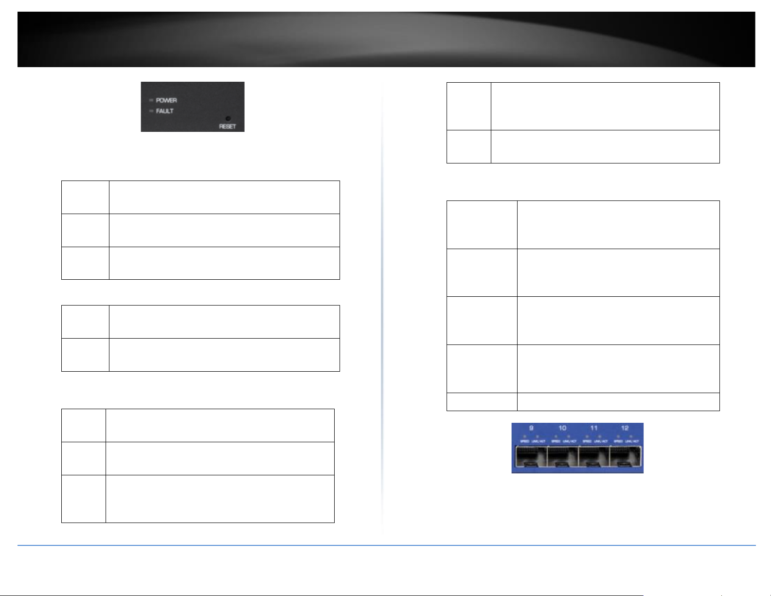
Diagnostic LEDs
Power LED
On
:
When the Power LED is on, the device is receiving
power.
Off
:
When the Power LED is off, the power adapter is
not connected or the device is not receiving power.
Blinking
:
When the Power LED is blinking, the switch is
receiving power and is botting up
Fault LED
Amber
On
:
When the Fault LED is on, there is an error with the
switch.
Off
:
When the Fault LED is off, there is no error with the
switch.
Ethernet Port LEDs (1-8)
Green
on
:
When the Green LED is on, the respective port is
connected to a 2.5/5/10Gbps Ethernet network.
Amber
on
:
When the Green LED lights on, the respective port
is connected to a 100/1000Mbps Ethernet network.
Green
Blinking
:
When the LED is blinking green, the port is
transmitting or receiving data on the network at
2.5/5/10Gbps speed.
Amber
Blinking
:
When the LED is blinking amber, the port is
transmitting or receiving data on the network at
100/1000Mbps speed.
Off
When the LED is off, the respective port is
disconnected.
SFP Slots (9-12)
Green on
:
When the SFP LED is on, the link established
using the SFP module is operating at 10Gbps
speed.
Green
blinking
:
When the SFP LED is blinking, the port is
transmitting or receiving data on through the
10Gbps link established.
Amber on
:
When the SFP LED is on, the link established
using the SFP module is operating at
1000Mbps speed.
Amber
blinking
:
When the SFP LED is blinking, the port is
transmitting or receiving data on through the
1000Mbps link established.
Off : No link established.
Page 15
© Copyright 2022 TRENDnet. All Rights Reserved.
1
TRENDnet User’s Guide
Multi-Gig Web Smart Switch Series
TEG-3524S Overview
Package Contents
In addition to your switch, the package includes:
• Quick Installation Guide
• Power cord (1.8 m / 6 ft.)
• Rack mount kit
If any package contents are missing or damaged, please contact the retail store, online
retailer, or reseller/distributor from which the product was purchased.
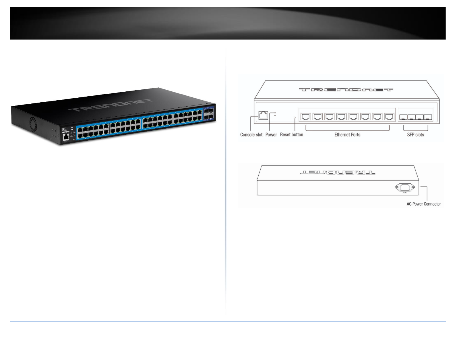
TEG-3524S Hardware Features
Front View
Rear View
• Power LED Indicator – LED indicators for power and fault
• Reset Button – Press and hold the button 1~3 seconds and release to reboot
the device. Pressing the button more than 5 seconds will reset the switch to
factory defaults. The ports LEDs will turn off to indicate that the reset was
initiated.
• Ethernet Ports (1-8) – Connect network devices at 10Gbps / 5Gbps 2.5Gbps /
1Gbps / 100Mbps speeds.
• SFP Slots (9-12) – Supports optional 10Gbps or 1Gbps mini-GBIC SFP modules
for uplink or downlink connections.
Page 16
© Copyright 2022 TRENDnet. All Rights Reserved.
2
TRENDnet User’s Guide
Multi-Gig Web Smart Switch Series
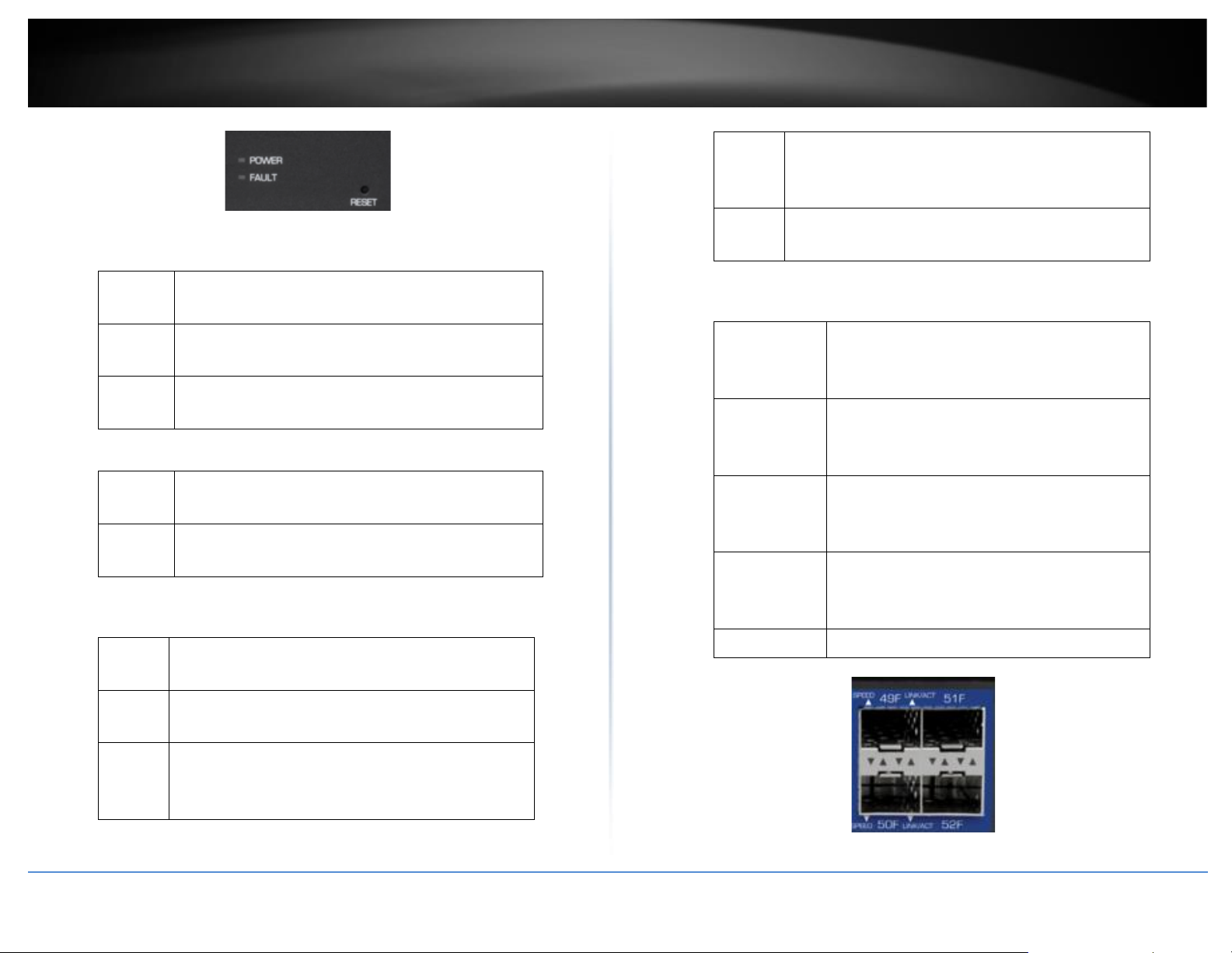
Diagnostic LEDs
• Power LED
On
:
When the Power LED is on, the device is receiving
power.
Off
:
When the Power LED is off, the power adapter is
not connected or the device is not receiving power.
Blinking
:
When the Power LED is blinking, the switch is
receiving power and is botting up
• Fault LED
Amber
On
:
When the Fault LED is on, there is an error with the
switch.
Off
:
When the Fault LED is off, there is no error with the
switch.
• Ethernet Port LEDs (1-48)
Green
on
:
When the Green LED is on, the respective port is
connected to a 2.5/5/10Gbps Ethernet network.
Amber
on
:
When the Green LED lights on, the respective port
is connected to a 100/1000Mbps Ethernet network.
Green
Blinking
:
When the LED is blinking green, the port is
transmitting or receiving data on the network at
2.5/5/10Gbps speed.
Amber
Blinking
:
When the LED is blinking amber, the port is
transmitting or receiving data on the network at
100/1000Mbps speed.
Off
When the LED is off, the respective port is
disconnected.
• SFP Slots (49-52)
Green on
:
When the SFP LED is on, the link established
using the SFP module is operating at 10Gbps
speed.
Green
blinking
:
When the SFP LED is blinking, the port is
transmitting or receiving data on through the
10Gbps link established.
Amber on
:
When the SFP LED is on, the link established
using the SFP module is operating at
1000Mbps speed.
Amber
blinking
:
When the SFP LED is blinking, the port is
transmitting or receiving data on through the
1000Mbps link established.
Off : No link established.
Page 17
© Copyright 2022 TRENDnet. All Rights Reserved.
3
TRENDnet User’s Guide
Multi-Gig Web Smart Switch Series
Switch Installation
Desktop Hardware Installation
The site where you install the hub stack may greatly affect its performance. When
installing, consider the following pointers:
Note: Your switch model may be different than the one shown in the example
illustrations.
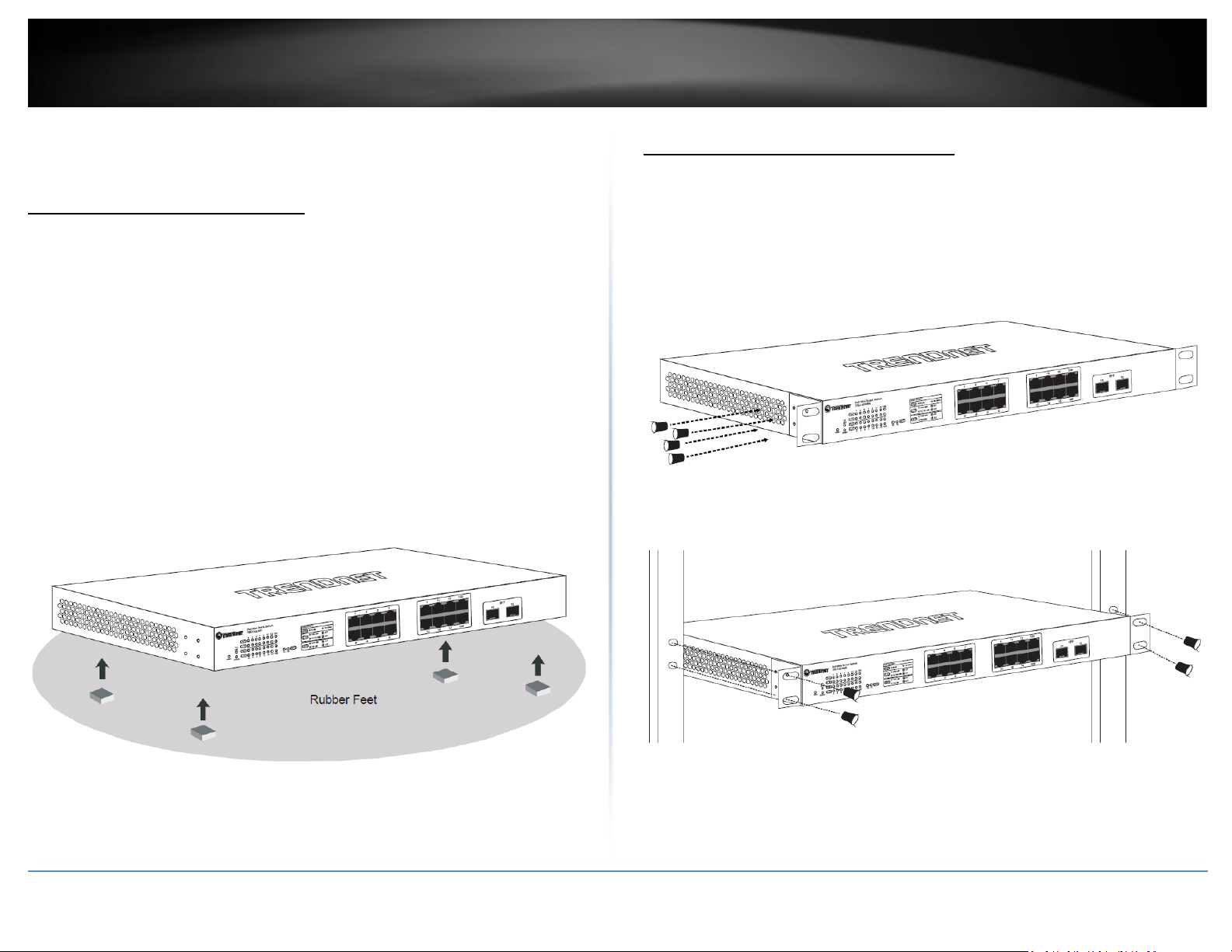
• Install the Switch in a fairly cool and dry place.
• Install the Switch in a site free from strong electromagnetic field generators (such
as motors), vibration, dust, and direct exposure to sunlight.
• Leave at least 10cm of space at the front and rear of the hub for ventilation.
• Install the Switch on a sturdy, level surface that can support its weight, or in an
EIA standard-size equipment rack. For information on rack installation, see the
next section, Rack Mounting.
• When installing the Switch on a level surface, attach the rubber feet to the
bottom of each device. The rubber feet cushion the hub and protect the hub
case from scratching.
Rack Mount Hardware Installation
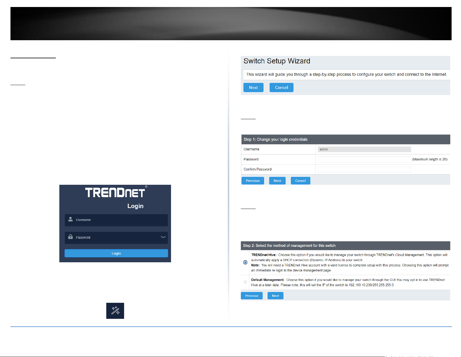
The switch can be mounted in an EIA standard-size, 19-inch rack, which can be placed in
a wiring closet with other equipment. Attach the mounting brackets at the switch’s
front panel (one on each side), and secure them with the provided screws.
Note: The switch model may be different than the one shown in the example
illustrations.
Then, use screws provided with the equipment rack to mount each switch in the rack.
Page 18
© Copyright 2022 TRENDnet. All Rights Reserved.
4
TRENDnet User’s Guide
Multi-Gig Web Smart Switch Series
Setup Wizard
Section A: Configuring the switch with TRENDnet Hive Cloud Management
Note: Configuration with TRENDnet Hive Cloud Management requires an existing
network with Internet access and DHCP server for automatic IP addressing. The switch
must be configured to reach the Internet in order to connect to your TRENDnet Hive
Cloud Management account.
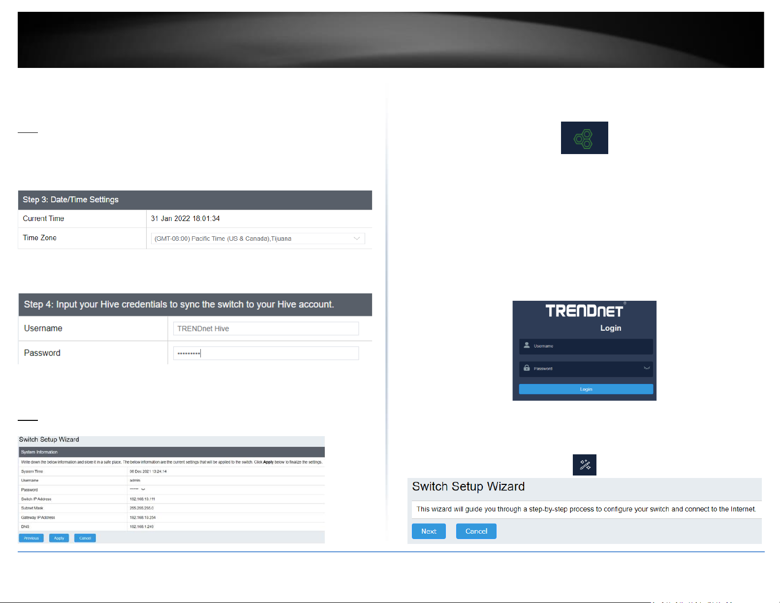
1. Assign a static IP address to your computer’s network adapter in the subnet of
192.168.10.x (e.g. 192.168.10.25) and a subnet mask of 255.255.255.0.
2. Open your web browser, and type the IP address of the switch in the address bar, and
then press Enter. The default IP address is 192.168.10.200.
3. Enter the User Name and Password, and then click Login. By default:
User Name: admin
Password: admin
Note: User name and password are case sensitive.
4. Select Next to move onto the next screen
Note: If the switch setup wizard does not appear, you can click the setup wizard button
in the top right section of the switch management page to access the switch setup
wizard.
5. Change your login password and click Next. The default password is admin.
Note: If entering a new password, please note that you will need to use the new
password when logging into the switch management page for local management access
moving forward.
6. For the method of management, select TRENDnet Hive.
Note: Configuration with TRENDnet Hive Cloud Management requires an existing
network with Internet access and DHCP server for automatic IP addressing. The switch
must be configured to reach the Internet in order to connect to your TRENDnet Hive
Cloud Management account.
Page 19
© Copyright 2022 TRENDnet. All Rights Reserved.
5
TRENDnet User’s Guide
Multi-Gig Web Smart Switch Series
7. After selecting TRENDnet Hive, click Next and change your computer’s network
adapter settings to obtain an IP address automatically to continue the rest of the setup
wizard.
Note: After selecting the TRENDnet Hive option and clicking Next, the switch will
immediately change the switch default IP address settings to DHCP and optain IP
address settings from your existing network.
8. Select your Time Zone, then click Next.
9. Enter the user account credentials for your TRENDnet Hive Cloud Management
account to register the switch with your account, then click Next.
10. The summary page will display all of the configuration settings that were applied
through the setup wizard. Click Apply to complete the setup wizard.
Note: You may want to note the new password and IP address settings for local
management access to the switch.
10. To verify the switch is now successfully registered with your TRENDnet Hive Cloud
Management account, the Hive button in the top right will be green to indicate
successful registration.
Section B: Configuring the switch for local network management
1. Assign a static IP address to your computer’s network adapter in the subnet of
192.168.10.x (e.g. 192.168.10.25) and a subnet mask of 255.255.255.0.
2. Open your web browser, and type the IP address of the switch in the address bar, and
then press Enter. The default IP address is 192.168.10.200.
3. Enter the User Name and Password, and then click Login. By default:
User Name: admin
Password: admin
Note: User name and password are case sensitive.
4. Select Next to move onto the next screen
Note: If the switch setup wizard does not appear, you can click the setup wizard button
in the top right section of the switch management page to access the switch setup
wizard.
Page 20
© Copyright 2022 TRENDnet. All Rights Reserved.
6
TRENDnet User’s Guide
Multi-Gig Web Smart Switch Series
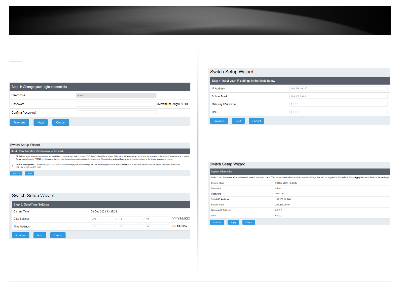
5. Change your login password and click Next. The default password is admin.
Note: If entering a new password, please note that you will need to use the new
password when logging into the switch management page for local management access
moving forward.
6. For the method of management, select Default Management.
7. Configure the switch date and time settings, then click Next.
8. Configure the switch IP address, subnet mask, gateway IP address, and DNS settings
to match the requirements of your existing network using the fields provided, then click
Next.
Note: If the switch IP address settings are changed to a different IP network subnet such
as 192.168.1.x, 192.168.2.x, etc. your computer’s network adapter settings will need to
be changed match the new IP address settings configured on the switch in order to
access the switch management page.
9. The summary page will display all of the configuration settings that were applied
through the setup wizard. Click Apply to complete the setup wizard.
Note: You may want to note the new password and IP address settings for local
management access to switch.
Page 21
© Copyright 2022 TRENDnet. All Rights Reserved.
7
TRENDnet User’s Guide
Multi-Gig Web Smart Switch Series
Basic IP Configuration
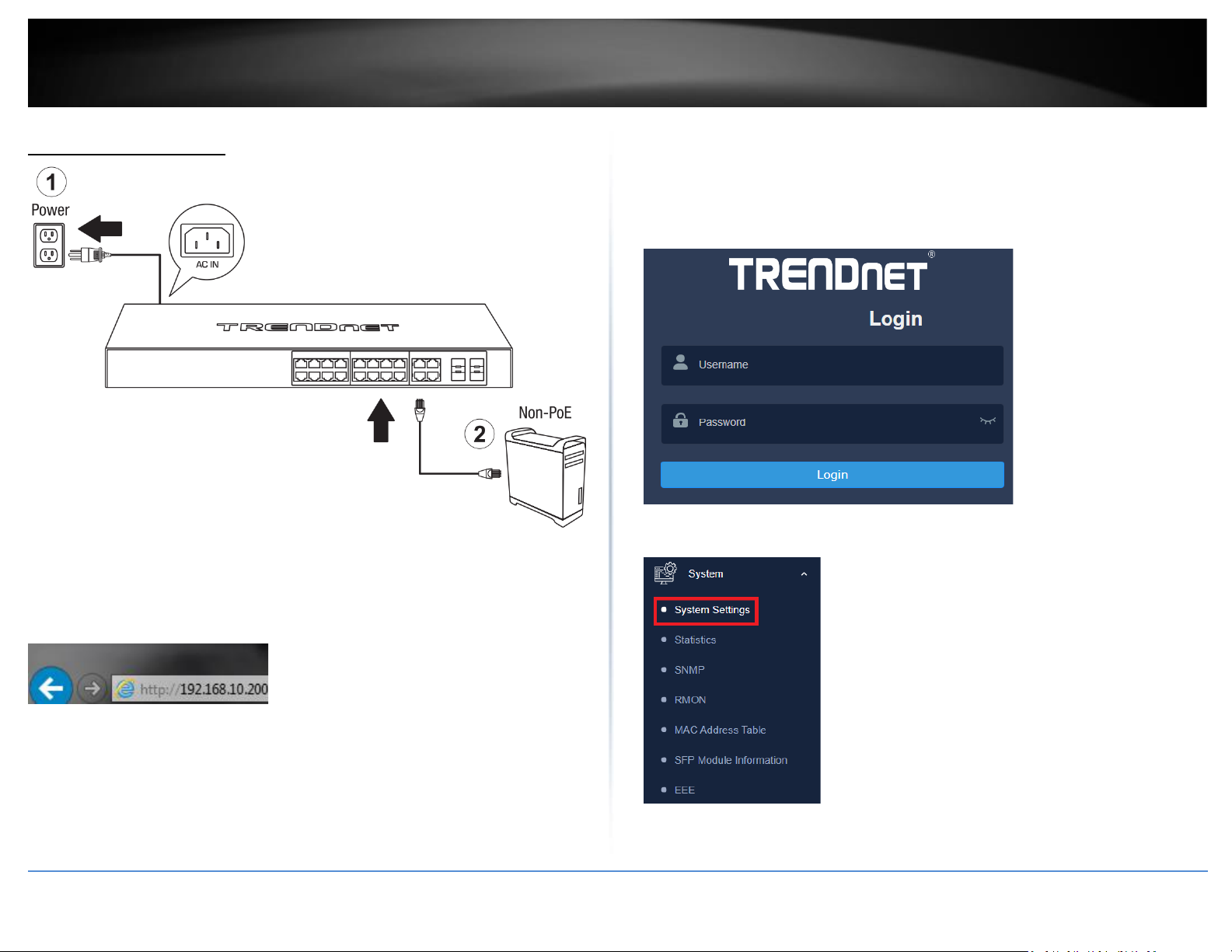
3. Assign a static IP address to your computer’s network adapter in the subnet of
192.168.10.x (e.g. 192.168.10.25) and a subnet mask of 255.255.255.0.
4. Open your web browser, and type the IP address of the switch in the address bar, and
then press Enter. The default IP address is 192.168.10.200.
5. Enter the User Name and Password, and then click Login. By default:
User Name: admin
Password: password
Note: User name and password are case sensitive.
6. Click System, and then click System Settings.
Page 22
© Copyright 2022 TRENDnet. All Rights Reserved.
8
TRENDnet User’s Guide
Multi-Gig Web Smart Switch Series
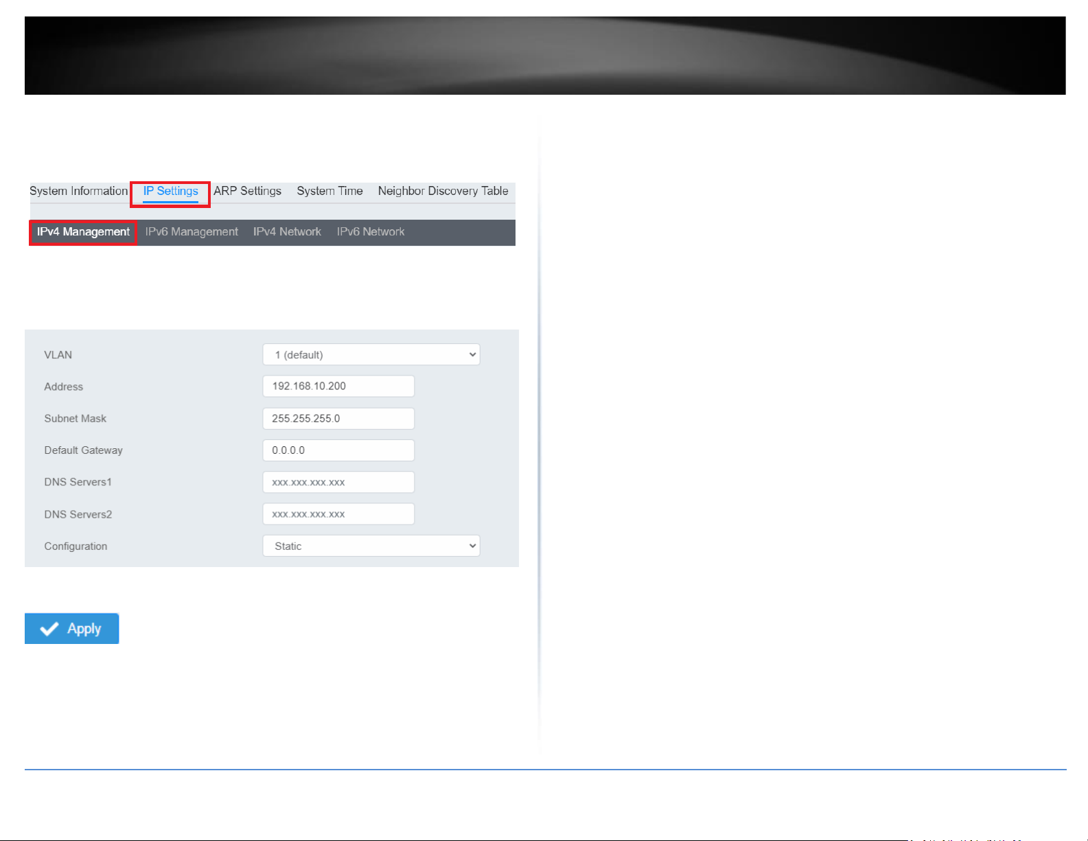
7. Click IP Settings and then click IPv4 Management.
8. Configure the switch’s IP address settings to be within your network subnet, then
click Apply to save your settings.
Note: All other functions of this page will be explained in detail in its respective section.
Note: Be sure to re-log back into the switch using the new IP address and save the
configuration to your flash.
Page 23
© Copyright 2022 TRENDnet. All Rights Reserved.
9
TRENDnet User’s Guide
Multi-Gig Web Smart Switch Series
Connect additional devices to your switch
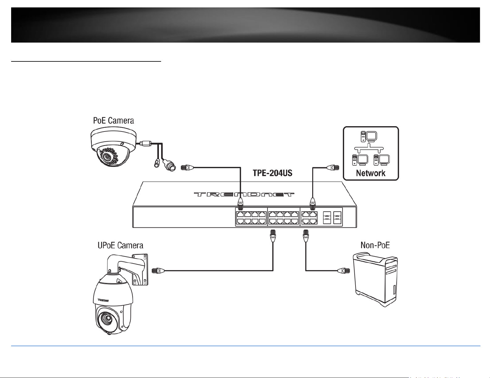
You can connect computers or other network devices to your switch using Ethernet cables to connect them to one of the available Gigabit Ethernet Ports, Gigabit Ethernet PoE Ports,
Gigabit Ethernet PoE+ Ports, Gigabit Ethernet UPoE Ports, or SFP Ports. Check the status of the LED indicators on the front panel of your switch to ensure the physical cable connection
from your computer or device. You can use either the Gigabit Ethernet ports or SFP connections as network uplinks. (SFP modules sold separately)
Note: If you encounter issues connecting to your network, there may be a problem with your computer or device network settings. Please ensure that your computer or device network
settings (also called TCP/IP settings) are configured properly within the network subnet your switch is connected.
Note: Your switch model may be different than the one shown in the example illustrations.
Page 24
© Copyright 2022 TRENDnet. All Rights Reserved.
10
TRENDnet User’s Guide
Multi-Gig Web Smart Switch Series
Access your switch management page
Note: Your switch default management IP address http://192.168.10.200 is accessed
through the use of your Internet web browser (e.g. Internet Explorer®, Firefox®,
Chrome™, Safari®, Opera™) and will be referenced frequently in this User’s Guide.
Throughout this user’s guide, the term Web Configuration will be used to reference
access from web management page.
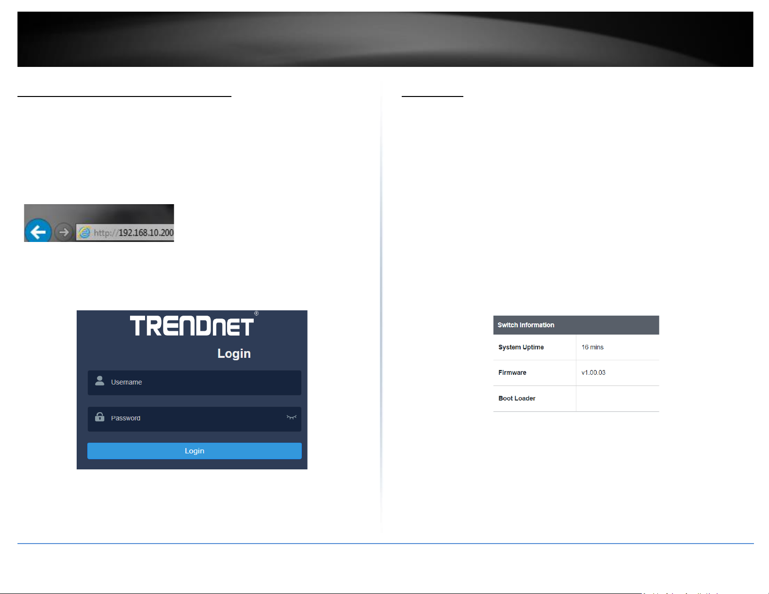
1. Open your web browser and go to its IP address (default: http://192.168.10.200).
Your switch will prompt you for a user name and password.
2. Enter the user name and password. By default:
User Name: admin
Password: password
Note: User Name and Password are case sensitive.
Dashboard
View your switch status information
Dashboard
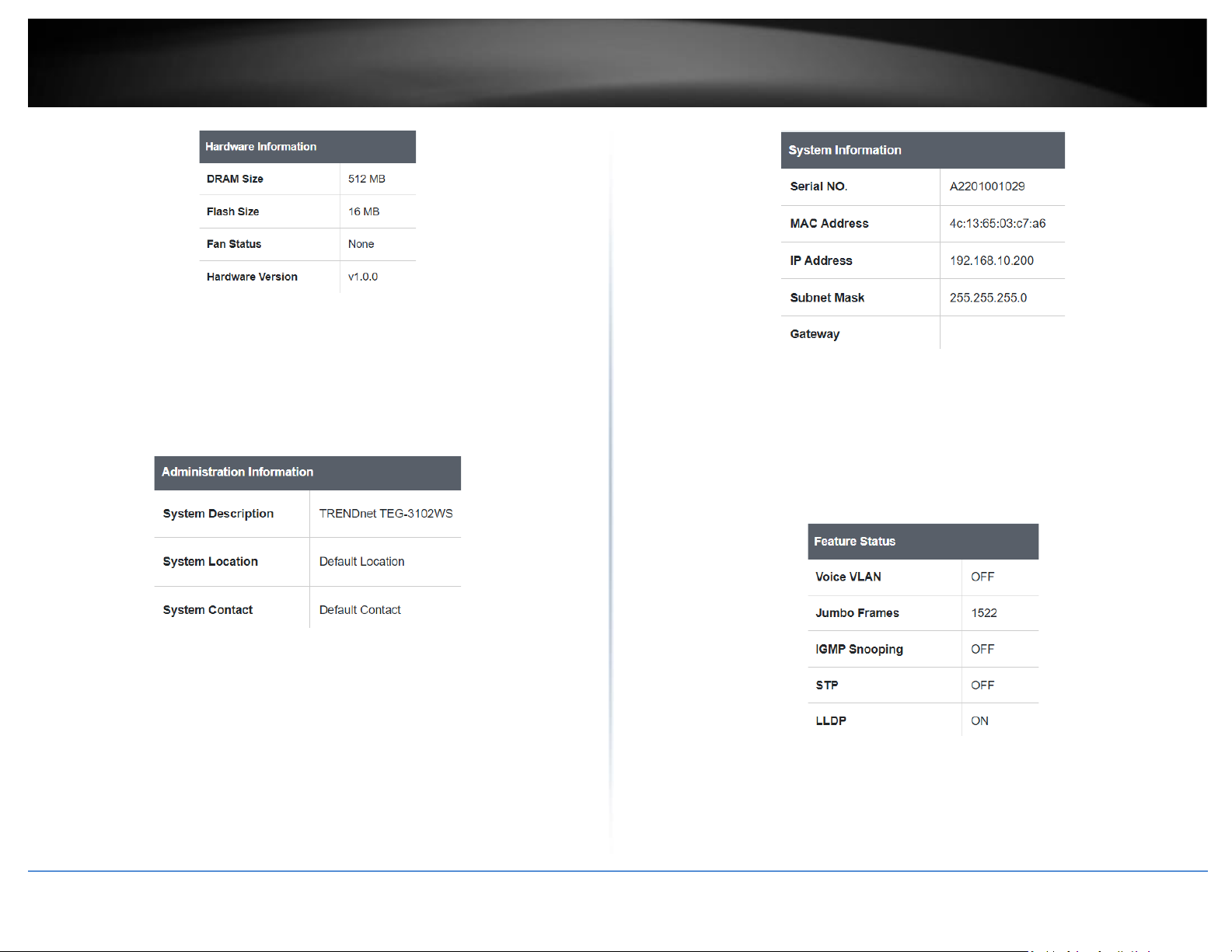
You may want to check the general system information of your switch such as firmware
version, boot loader information and system uptime. Other information includes H/W
version, RAM/Flash size, administration information, IPv4 and IPv6 information.
1. Log into your switch management page (see “Access your switch management page”
on page 5).
2. Click on Dashboard.
Switch Information
• System Uptime – The duration your switch has been running continuously
without a restart/power cycle (hard or soft reboot) or reset.
• Firmware: The current software or firmware version your switch is running.
• Boot Loader – The current boot loader version your switch is running.
Hardware Information
• DRAM Size: Displays your switch RAM memory size.
• Flash Size: Displays your switch Flash memory size.
• Fan Status: Displays the current status of your switch’s fan
• Hardware Version: Displays your switch’s current hardware version
Page 25
© Copyright 2022 TRENDnet. All Rights Reserved.
11
TRENDnet User’s Guide
Multi-Gig Web Smart Switch Series
Administration Information
• System Description – Displays the identifying system name of your switch. This
information can be modified under the System section.
• System Location - Displays the identifying system location of your switch. This
information can be modified under the System section.
• System Contact – Displays the identifying system contact or system administrator
of your switch. This information can be modified under the System section.
System MAC Address, IPv4 Information
• Serial No: Displays the serial number of the switch
• MAC Address: Displays the switch system MAC address.
• IP Address – Displays the current IPv4 address assigned to your switch.
• Subnet Mask – Displays the current IPv4 subnet mask assigned to your switch.
• Default Gateway – Displays the current gateway address assigned to your switch.
IPv6 Information
• Voice VLAN: Displays if your switch has Voice VLAN enabled or disabled
• Jumbo Frames: Displays the size of Jumbo Frames that is supported.
• IGMP Snooping: Displays if your switch has IGMP Snooping enabled or disabled
• STP: Displays the current status of STP
• LLDP: Displays the current status ofLLDP
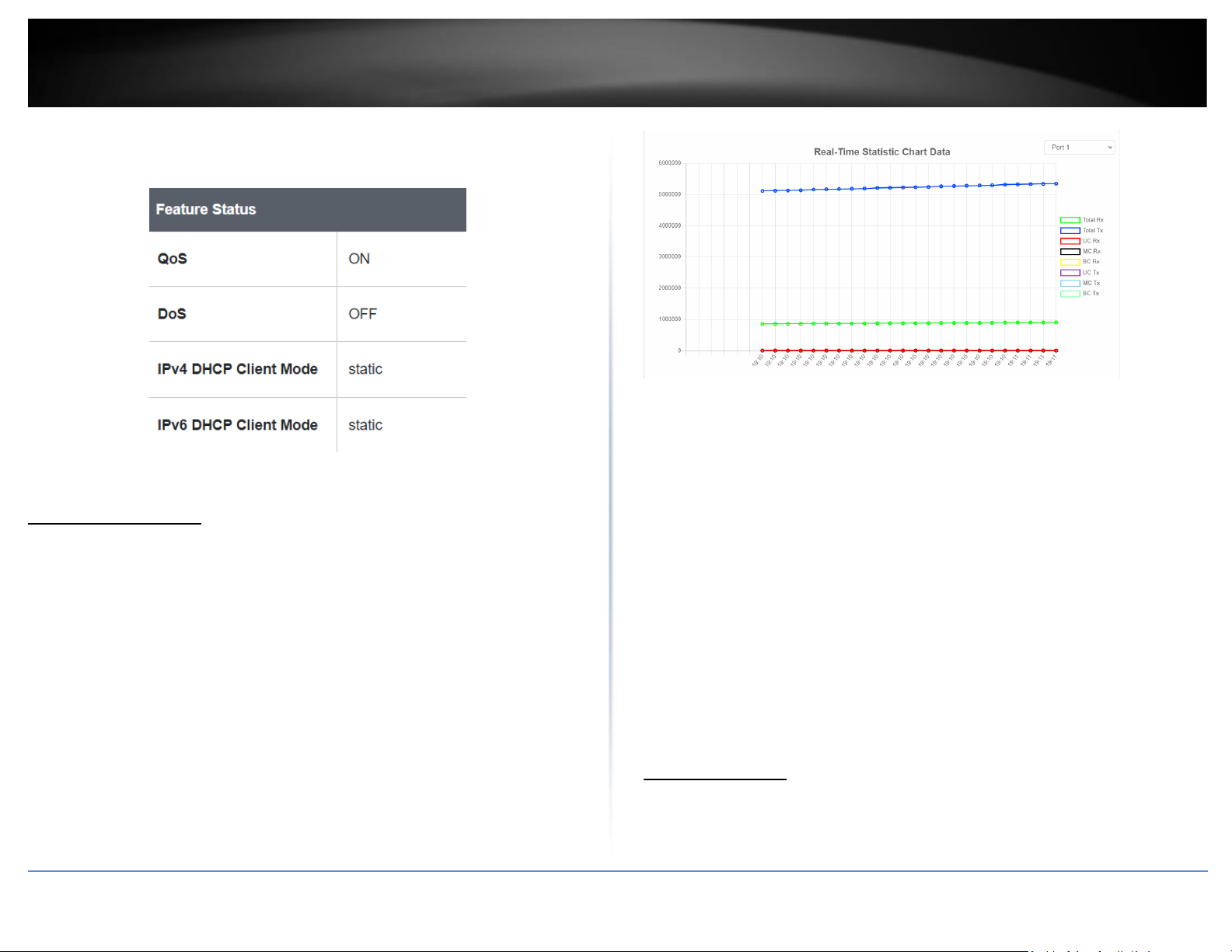
Automatic Network Features
• QoS: Displays if your switch has QoS enabled or disabled
• DoS: Displays if your switch has DoS enabled or disabled
• IPv4 DHCP Client Mode: Displays if your switch IPv4 address setting is set to
DHCP client.
Page 26
© Copyright 2022 TRENDnet. All Rights Reserved.
12
TRENDnet User’s Guide
Multi-Gig Web Smart Switch Series
• IPv6 DHCP Client Mode: Displays if your switch IPv6 address setting is set to
DHCP client.
Real-time Statistics
View your switch status information
Dashboard > Real-time Statistics
1. Log into your switch management page (see “Access your switch management page”
on page 5).
2. Click on Dashboard, then click on Real-time Statistics. The switch view shows the
ports that are connected. Select Status, Duplex, Speed, or PoE to display which ports
are currently using the selected feature.
3. Select the port from the drop down menu to review the current settings.
4 Total(Rx): The total number of packets received
5 Total(TX): The total number of packets transmitted
6 UC (Rx): The number of Unicast packets received
7 MC(Rx): The number of Multicast packets received
8 BC(Rx): The number of Broadcast packets received
9 UC(Tx): The number of Unicast packets transmitted
10 MC(Tx): The number of Multicast packets transmitted
11 BC(Tx): The number of Broadcast packets transmitted
System
System Settings
Set your system information
System > System Settings
Page 27
© Copyright 2022 TRENDnet. All Rights Reserved.
13
TRENDnet User’s Guide
Multi-Gig Web Smart Switch Series
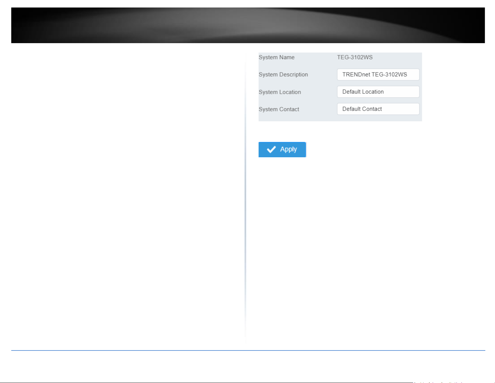
This section explains how to assign a name, location, and contact information for the
switch. This information helps in identifying each specific switch among other switches
in the same local area network. Entering this information is optional.
1. Log into your switch management page (see “Access your switch management page”
on page 5).
2. Click on System, and click on System Management.
3. Review the settings. When you have completed making changes, click Apply to save
the settings.
• System Name - Specifies the Switch model. You cannot change
this parameter.
• System Object ID - Indicates the unique SNMP MIB object
identifier that identifies the switch model. You cannot change this
parameter.
• System Description - Specifies a name for the switch, the name is
optional and may contain up to 255 characters.
• System Location - Specifies the location of the switch. The
location is optional and may contain up to 255 characters.
• System Contact - Specifies the name of the network administrator
responsible for managing the switch. This contact name is
optional and may contain up to 255 characters.
4. Click Apply.
Note: Clicking Apply will save all configuration changes to the NV-RAM to ensure that if
the switch is rebooted or power cycled, the configuration changes will still be applied.
Page 28
© Copyright 2022 TRENDnet. All Rights Reserved.
14
TRENDnet User’s Guide
Multi-Gig Web Smart Switch Series
L3 Feature
IPv4 Interface
System > System Settings > IP Settings
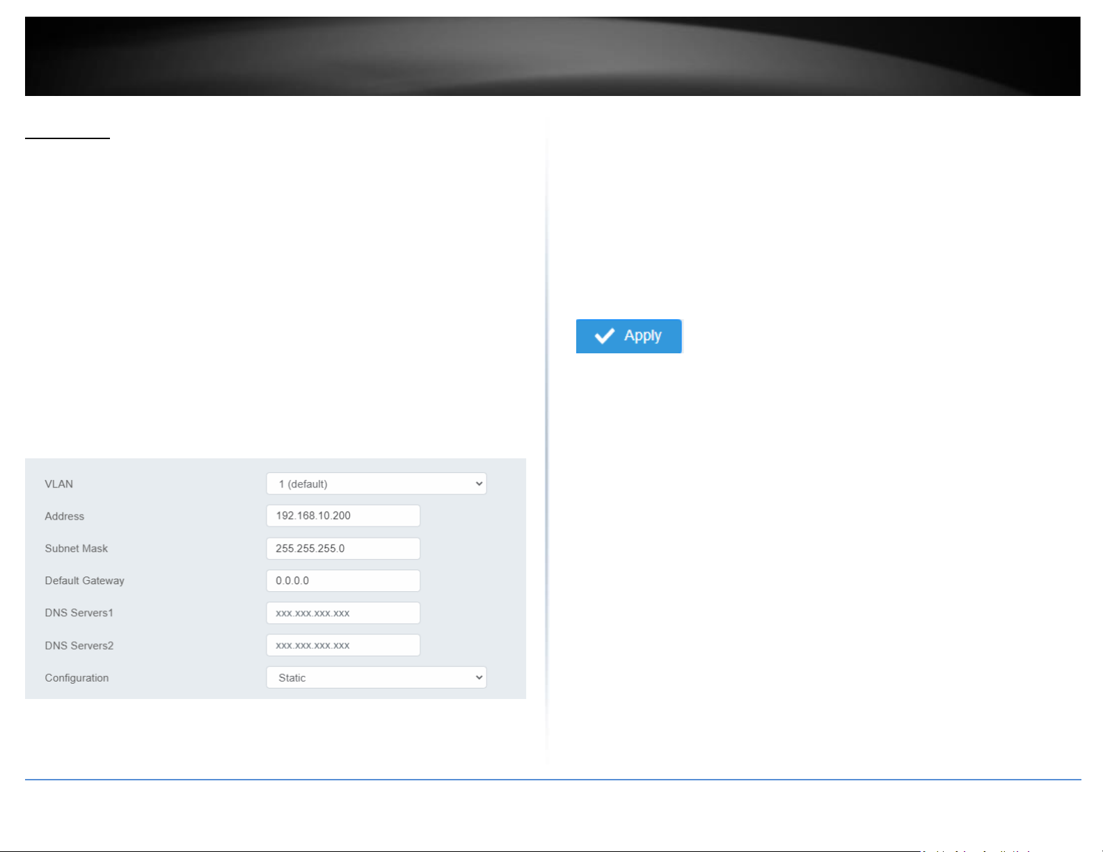
This section allows you to change your switch IPv4 address settings and additionally
create and assign the aforementioned address to VLANs. Typically, the IP address
settings should be changed to match your existing network subnet in order to access the
switch management page on your network.
Default Switch IPv4 Address: 192.168.10.200
Default Switch IPv4 Subnet Mask: 255.255.255.0
1. Log into your switch management page (see “Access your switch management page”
on page 5).
2. Click on System, System Settings, and then IP Settings.
4. To change the IPv4 IP address associated with a specific VLAN, select the VLAN ID
from the drop down menu under VLAN.
5. Review the settings. When you have completed making changes, click Apply to save
the settings.
• VLAN: Select the VLAN ID you wish to configure. .
• Address: Enter the new switch IP address you would like to statically assign.
(e.g. 192.168.200.200)
• Subnet Mask: Enter the new switch subnet mask. (e.g. 255.255.255.0)
• Default Gateway: Enter the IP address of your gateway device (ie: router)
• DNS Servers 1 / DNS Servers 2: Enter the IP address of a DNS server to use. (ie:
8.8.8.8.8 for Google’s DNS server)
• Configuration: Select Static to statically assign an IP address and subnet mask,
select DHCP to automatically request one from your networks DHCP server.
6. At the top right of the screen, click Apply.
Note: This step saves all configuration changes to the NV-RAM to ensure that if the
switch is rebooted or power cycled, the configuration changes will still be applied.
Page 29
© Copyright 2022 TRENDnet. All Rights Reserved.
15
TRENDnet User’s Guide
Multi-Gig Web Smart Switch Series
IPv4 ARP Aging Time
System > System Settings > ARP Settings
This section allows you to set the timeout for the switch’s ARP Table per each
configured VLAN.
1. Log into your switch management page (see “Access your switch management page”
on page 5).
2. Click on System, System Settings, and then ARP Settings.
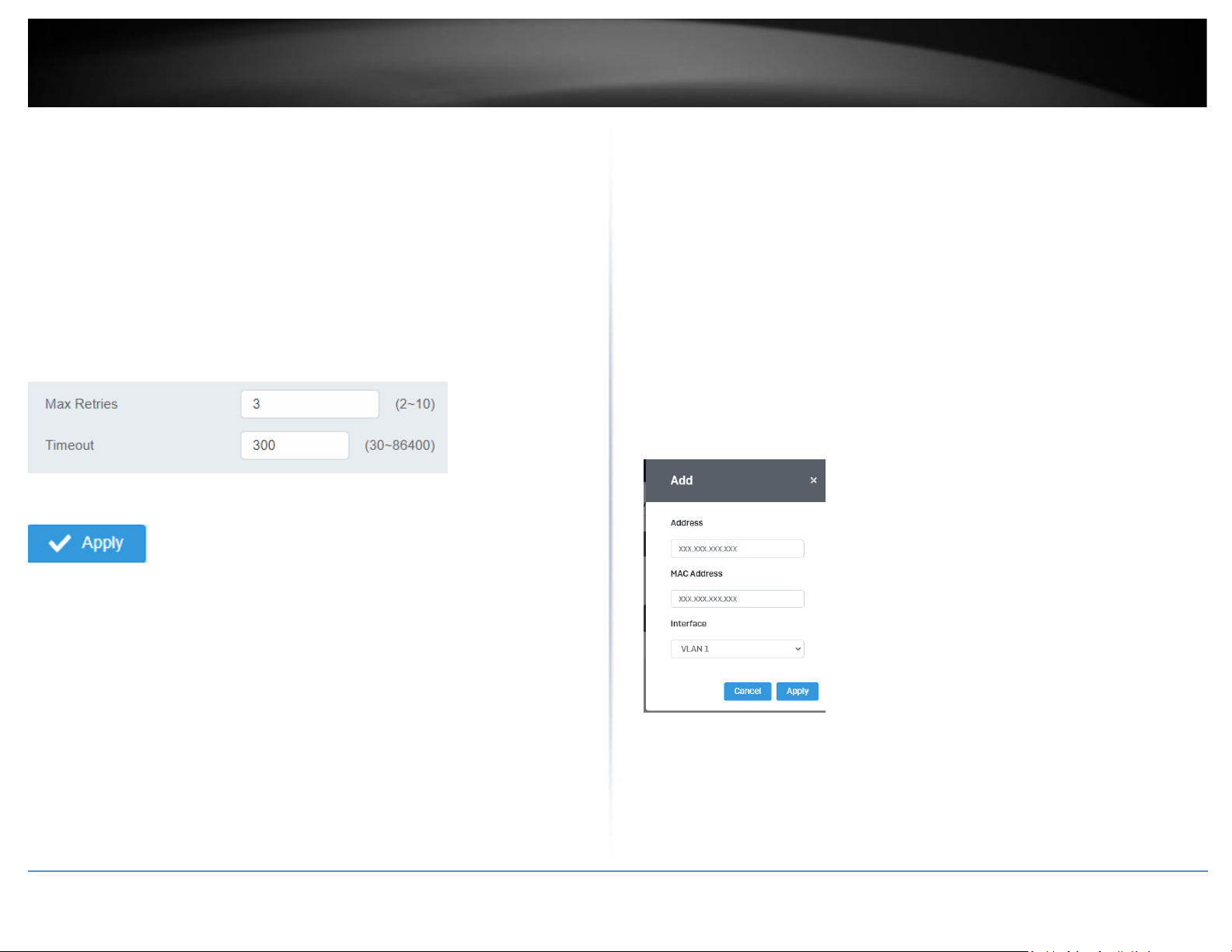
3. Edit the Max Retries and Timeout
4. At the top right of the screen, click Apply.
Note: This step saves all configuration changes to the NV-RAM to ensure that if the
switch is rebooted or power cycled, the configuration changes will still be applied.
IPv4 Static ARP
System > System Settings > ARP Settings > ARP Table
This section allows you to statically set ARP entries per each configured VLAN.
1. Log into your switch management page (see “Access your switch management page”
on page 5).
2. Click on System, System Settings, ARP Settings and then ARP Table.
3. To add a static ARP entry, click Add to fill out the fields and then press Apply. To
delete an entry, press Delete in the lower table.
• Address: enter the IP address you would like to statically set to the ARP table.
• MAC Address: enter the MAC address that you would like to assign to the IP
entered above.
• Interface: Select the VLAN ID to add the ARP entry to
4. At the bottom of the left hand panel, click Apply.
5. Click the Apply button on the top right of the screen.
Note: This step saves all configuration changes to the NV-RAM to ensure that if the
switch is rebooted or power cycled, the configuration changes will still be applied.
Page 30
© Copyright 2022 TRENDnet. All Rights Reserved.
16
TRENDnet User’s Guide
Multi-Gig Web Smart Switch Series
System Time
System > System Settings > System Time
This setting allows you to configure your IPv4/IPv6 DNS server settings for the purpose
or resolving hostnames. For example, when specifying your SNTP server time settings
via domain name, the switch will not be able to resolve the SNTP domain name specified
until you configure the switch DNS server setting.
1. Log into your switch management page (see “Access your switch management page”
on page 5).
2. Click on System, then click on System Settings, and click on System Time.
3. Review the settings below and click Apply to save your settings.
Page 31
© Copyright 2022 TRENDnet. All Rights Reserved.
17
TRENDnet User’s Guide
Multi-Gig Web Smart Switch Series
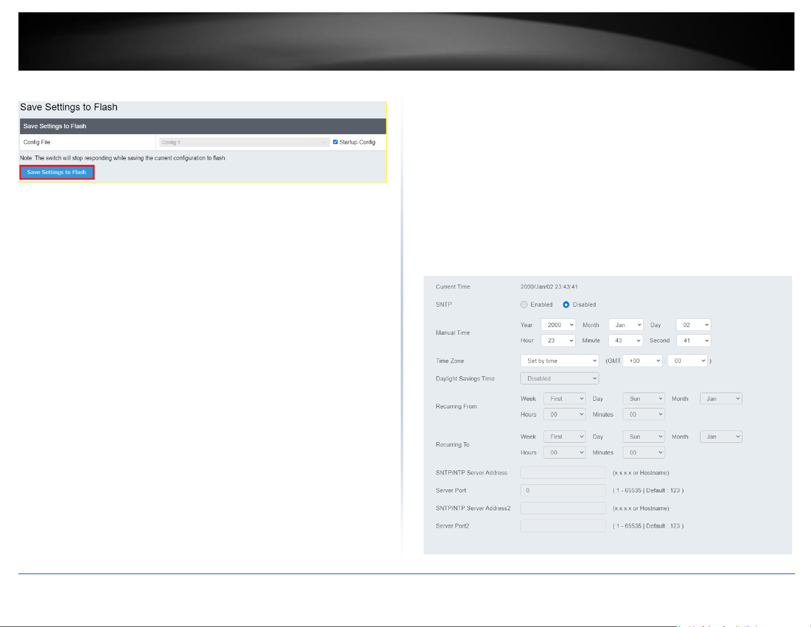
• Current Time: Displays the current time that is saved on your switch
• SNTP: Enable to allow the switch to automatically pull the time from an
SNTP/NTP Address, and select disable to manually input the time.
• Manual Time: Manually input the current date and time
• Time Zone: Sets the current time zone you are in
• Daylight Savings Time: Enable to set if daylight savings is on and disable if it is
not currently in daylight savings
• Recurring From / Recurring To: Configures when daylight savings goes into
effect and when it ends.
• SNTP/NTP Server Address: Sets the primary and back up SNTP/NTP Server
Address
• Server Port: Sets the port that the switch needs to access.
4. At the top right of the screen, click Apply.
Note: This step saves all configuration changes to the NV-RAM to ensure that if the
switch is rebooted or power cycled, the configuration changes will still be applied.
SNMP
Global Settings
System > SNMP > Global Setting
1. Log into your switch management page (see “Access your switch management page”
on page 5).
2. Click on System, click on SNMP, and click on Global Settings.
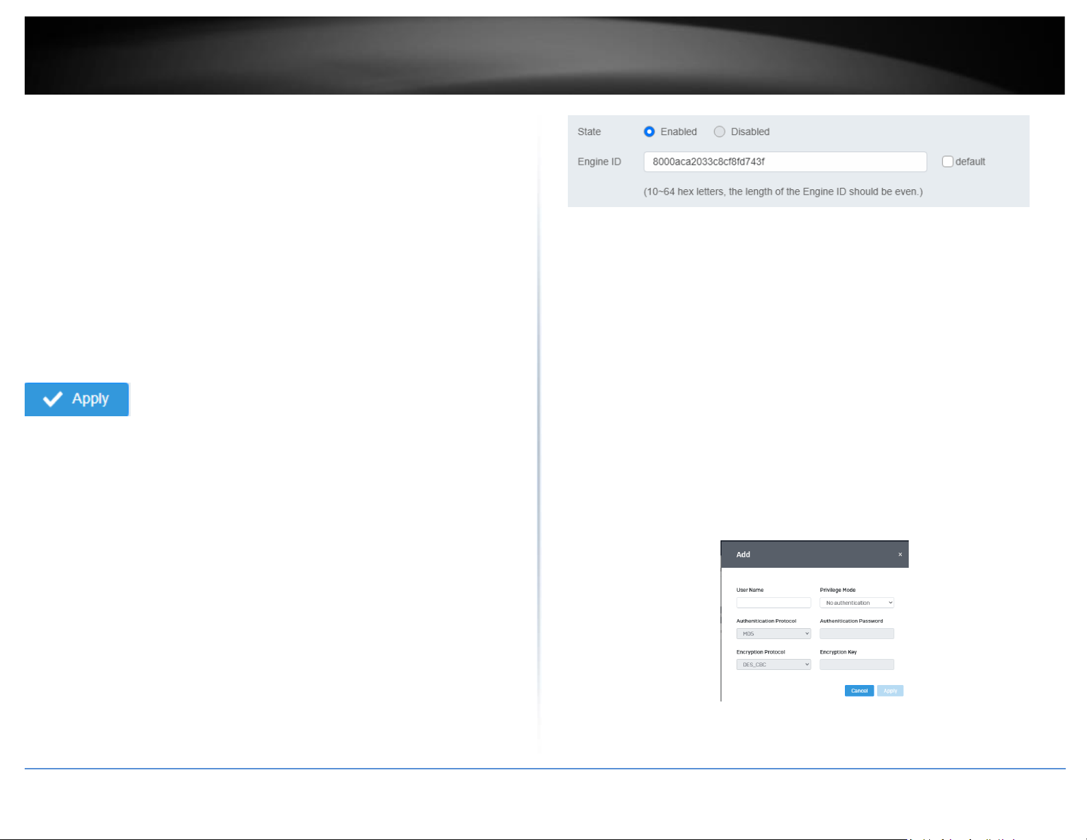
3. Select Enabled to enable SNMP or Disabled to disable it.
4. Input the SNMP OID engine
User List
System > SNMP > User List
1. Log into your switch management page (see “Access your switch management page”
on page 5).
2. Click on System, click on SNMP, and click on User List.
3. Click Add to add username to the user list.
4. Review the settings and click Apply.
• User Name: Enter the User Name to grant access to
Page 32
© Copyright 2022 TRENDnet. All Rights Reserved.
18
TRENDnet User’s Guide
Multi-Gig Web Smart Switch Series
• Privilege Mode: Select the level of privilege given
• Authentication Protocol: Select the type of protocol used for
authentication
• Authentication Password: Input the password for the SNMP user
• Encryption Protocol: Select the encryption protocol type
• Encryption Key: Input the encryption key
Community List
System > SNMP > Community List
1. Log into your switch management page (see “Access your switch management page”
on page 5).
2. Click on System, click on SNMP, and click on Community List.
3. Select Edit to edit the selected community name or Delete to delete it.
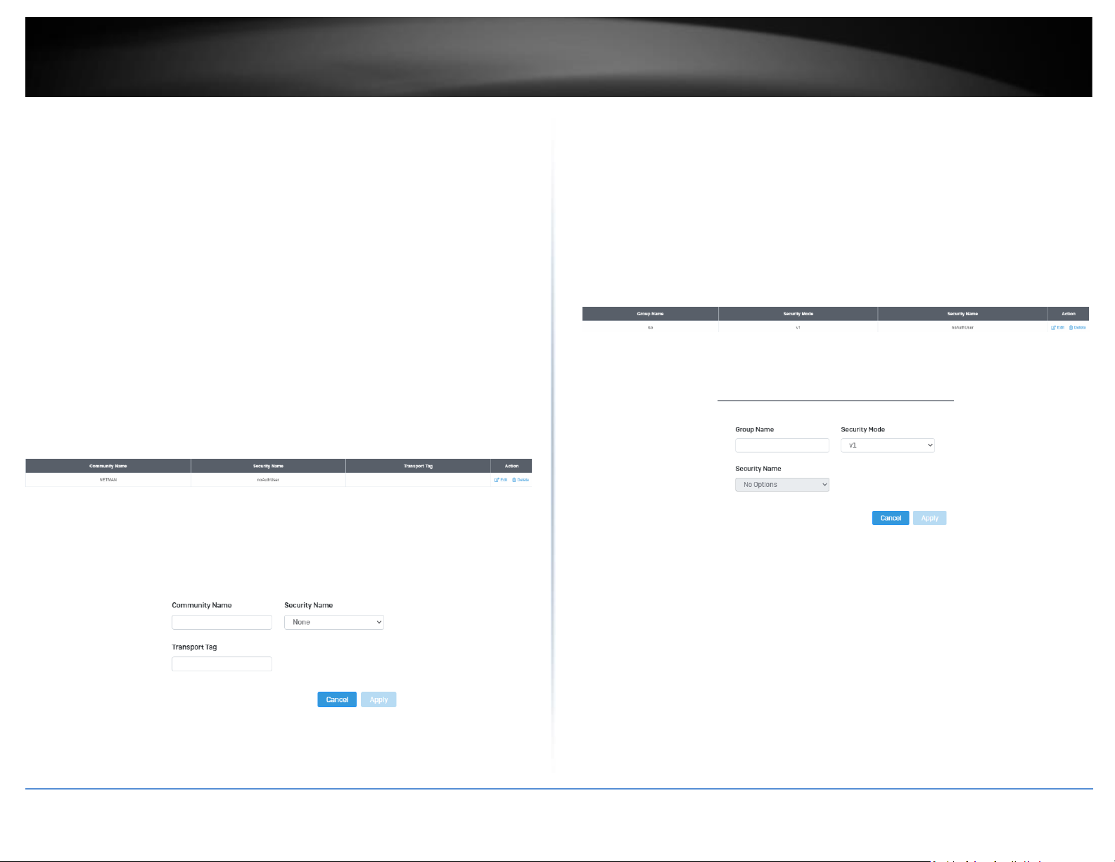
4. To add a new entry, click the Add button
5. Review the settings and click Apply,
• Community Name: Input the community name for the new entry
• Security Name: Select the security type
• Transport Tag: Input the transport tag in the field
Group List
System > SNMP > Group List
1. Log into your switch management page (see “Access your switch management page”
on page 5).
2. Click on System, click on SNMP, and click on Group List.
3. Select Edit to edit the selected group name or Delete to delete it.
4. Click Add to add username to the user list.
5. Review the settings and click Apply,
• Group Name: Input the desired group name
• Security Mode: Select the security mode for this SNMP group
• Security Name: Select the Security name from the drop down
menu
Access List
System > SNMP > Access List
1. Log into your switch management page (see “Access your switch management page”
on page 5).
Page 33
© Copyright 2022 TRENDnet. All Rights Reserved.
19
TRENDnet User’s Guide
Multi-Gig Web Smart Switch Series
2. Click on System, click on SNMP, and click on Access List.
3. Select Edit to edit the selected group name or Delete to delete it.
4. Click Add to add username to the user list.
5. Review the settings and click Apply,
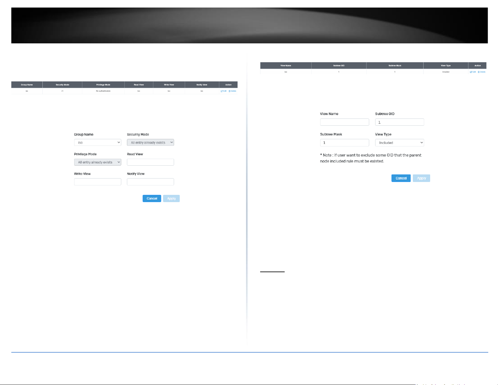
• Group Name: Select from the list of group names in the drop
down menu
• Security Mode: Select from the drop down menu the level of
security
• Read View: Input the items that are readable for this group
• Write View: Input the items that can be modified by this group
View List
System > SNMP > View List
1. Log into your switch management page (see “Access your switch management page”
on page 5).
2. Click on System, click on SNMP, and click on View List.
3. Select Edit to edit the selected group name or Delete to delete it.
4. Click Add to add username to the user list.
5. Review the settings and click Apply,
• View Name: Input the view name
• Subtree OID: Input the OID to be used
• Subtree Mask: Input the Subtree Mask
• View Type: Select Included or Excluded from the drop down
menu
RMON
Statistics
System > RMON > Stat List
You can remotely view individual port statistics with RMON by using your SNMP NMS
software and the RMON portion of the MIB tree.
1. Log into your switch management page (see “Access your switch management page”
on page 5).
Page 34
© Copyright 2022 TRENDnet. All Rights Reserved.
20
TRENDnet User’s Guide
Multi-Gig Web Smart Switch Series
2. Click on System, click on RMON, and click on Stat List.
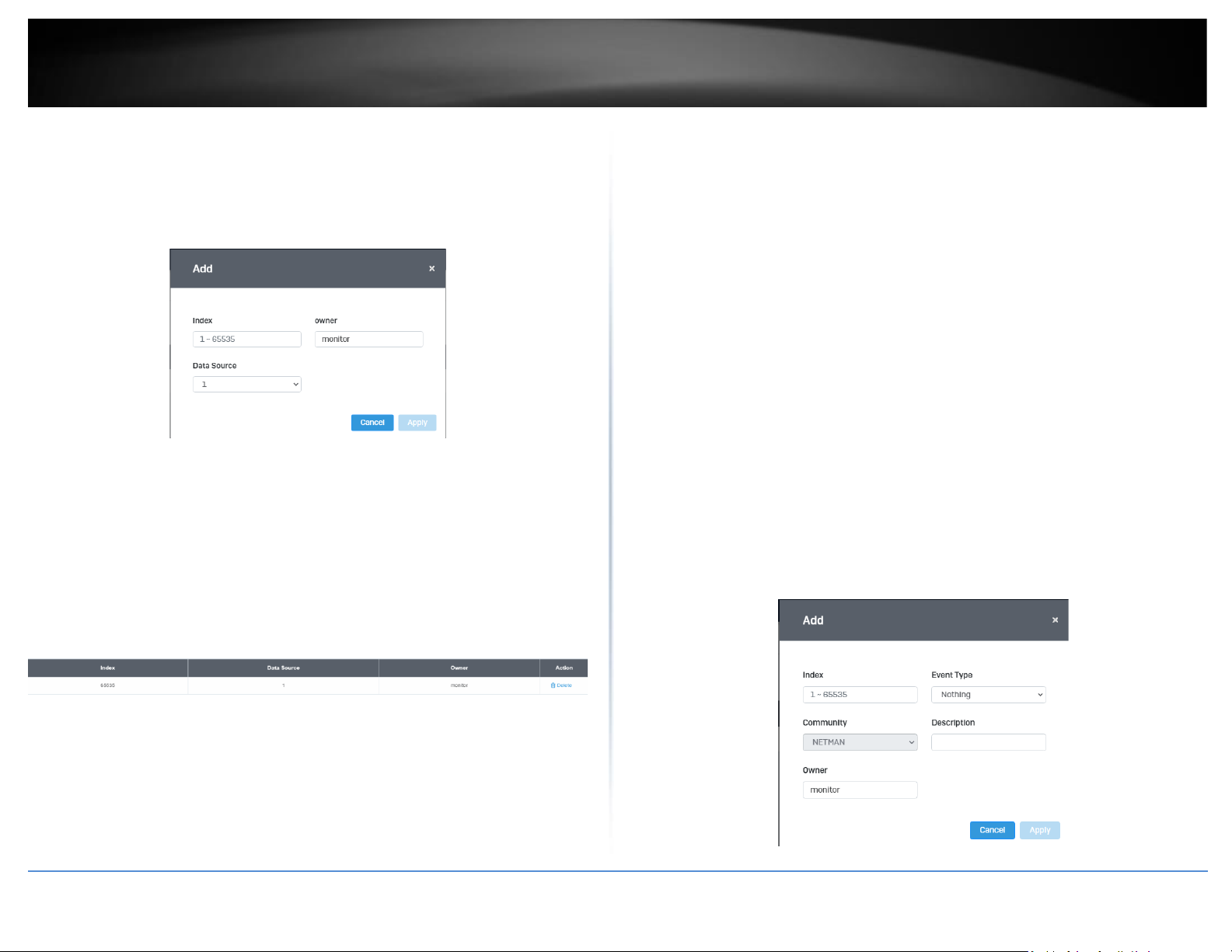
3. Click Add to add the entry to the table
4. Review the settings and click Apply.
• Index: This parameter specifies the ID number of the new group.
The range is 1 to 65535.
• Data Source: This parameter specifies the port where you want to
monitor the statistical information of the Ethernet traffic.
• Owner: This parameter is used to identify the person who created
an entry. It is primarily intended for switches that are managed by
more than one person, and is an optional field.
In the list, you can click Delete to delete the entry.
1. Statistic group— This group is used to view port statistics remotely
with SNMP programs.
2. History group— This group is used to collect histories of port statistics
to identify traffic trends or patterns.
3. Event group— This group is used with alarms to define the actions of
the switch when packet statistic thresholds are crossed.
4. Alarm group—This group is used to create alarms that trigger event
log messages or SNMP traps when statistics thresholds are exceeded.
Event List
System > RMON > Event List
The RMON (Remote Monitoring) MIB is used with SNMP applications to monitor the
operations of network devices. This Event group is used with alarms to define the
actions of the switch when packet statistic thresholds are crossed.
1. Log into your switch management page (see “Access your switch management page”
on page 5).
2. Click on System, click on RMON and click on Event List.
3. Click the Add button on the top right to enable RMON. Review and edit your settings.
Click Apply to save settings.
Page 35
© Copyright 2022 TRENDnet. All Rights Reserved.
21
TRENDnet User’s Guide
Multi-Gig Web Smart Switch Series
• Index: This parameter specifies the ID number of the new group.
The range is 1 to 65535.
• Event: Select the type of event that will trigger the alarm
• Description: Provide a name for this rule
• Owner: This parameter is used to identify the person who created
an entry. It is primarily intended for switches that are managed by
more than one person, and is an optional field
4. In the list, you can click Edit to modify an entry or click Delete or delete the entry.
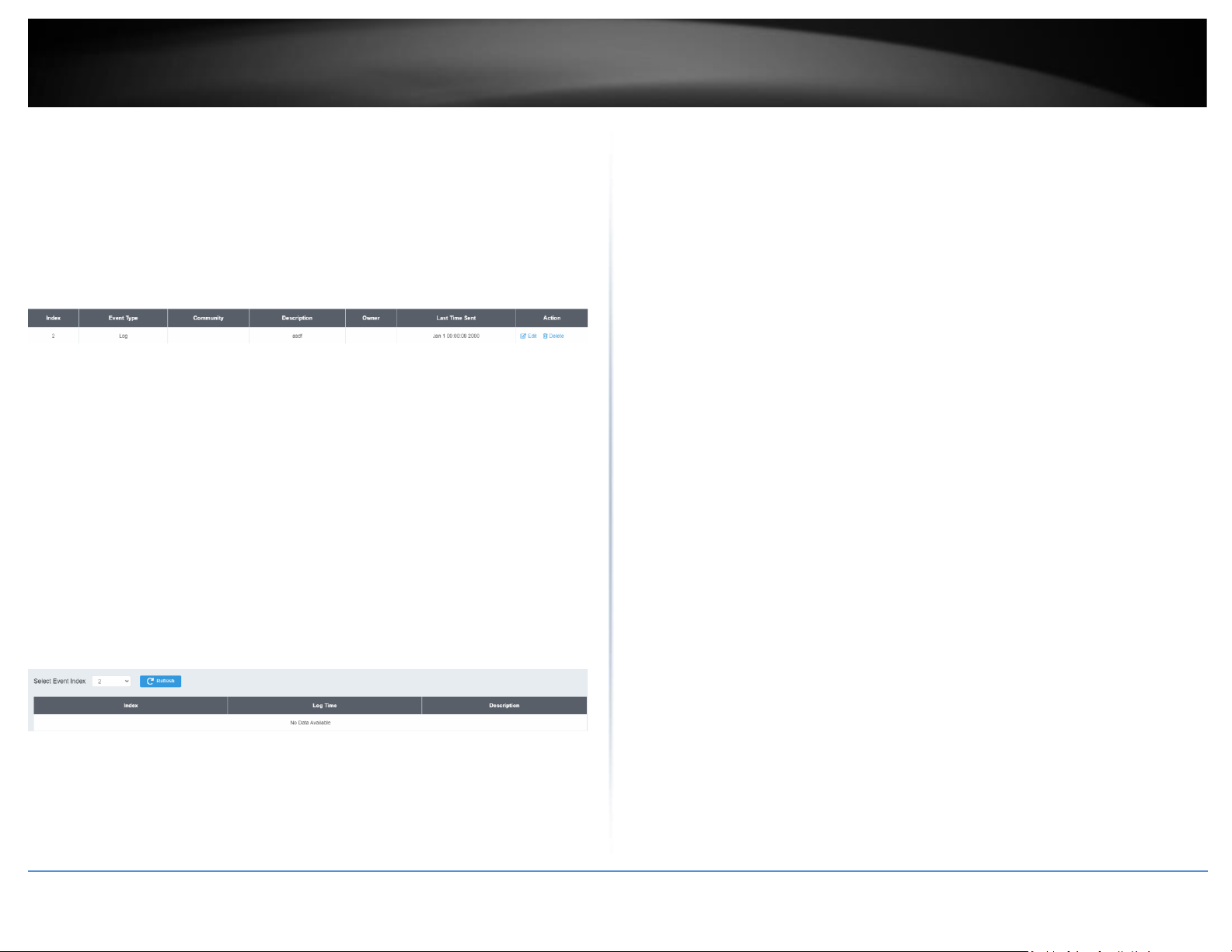
Event Log Table
System > RMON > Event Log Table
Any RMON events that were triggered will be displayed here.
1. Log into your switch management page (see “Access your switch management page”
on page 5).
2. Click on System, click on RMON, and click on Event Log Table.
3. Select the Event Index from the drop-down menu. Click the Refresh button if the page
needs to be refreshed.
Alarm List
System > RMON > Alarm List
RMON alarms are used to generate alert messages when packet activity on designated
ports rises above or falls below specified threshold values. The alert messages can take
the form of messages that are entered in the event log on the switch or traps that are
sent to your SNMP NMS software or both.
RMON alarms consist of two thresholds. There is a rising threshold and a falling
threshold. The alarm is triggered if the value of the monitored RMON statistic of the
designated port exceeds the rising threshold. The response of the switch is to enter a
message in the event log, send an SNMP trap, or both. The alarm is reset if the value of
the monitored statistic drops below the falling threshold.
The frequency with which the switch samples the thresholds of an alarm against the
actual RMON statistic is controlled by a time interval parameter. You can adjust this
interval for each alarm.
1. Log into your switch management page (see “Access your switch management page”
on page 5).
2. Click on System, click on RMON, and click on Alarm List.
3. Review the settings.
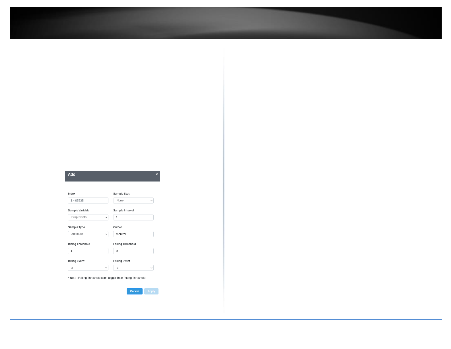
• Index: This parameter specifies the ID number of the new group. The range is 1
to 65535.
• Sample Interval: This parameter specifies the time (in seconds) over which the
data is sampled. Its range is 1 to 2147483647 seconds.
• Sample Variable: This parameter specifies the RMON MIB object that the event
is monitoring.
• Sample type: This parameter defines the type of change that has to occur to
trigger the alarm on the monitored statistic. There are two choices from the
pull-down menu - Delta value and Absolute value. Delta value- setting
compares a threshold against the difference between the current and previous
values of the statistic. Absolute value- setting compares a threshold against the
current value of the statistic.
• Owner: This parameter is used to identify the person who created an entry. It is
primarily intended for switches that are managed by more than one person,
and is an optional field
Page 36
© Copyright 2022 TRENDnet. All Rights Reserved.
22
TRENDnet User’s Guide
Multi-Gig Web Smart Switch Series
• Rising Threshold: This parameter specifies a specific value or threshold level of
the monitored statistic. When the value of the monitored statistic becomes
greater than this threshold level, an alarm event is triggered. The parameter’s
range is 1 to 2147483647.
• Falling Threshold: This parameter specifies a specific value or threshold level of
the monitored statistic. When the value of the monitored statistic becomes less
than this threshold level, an alarm event is triggered. The parameter’s range is
1 to 2147483647.
• Rising Event: This parameter specifies the event index for the rising threshold.
Its range is 1 to 65535. This field is mandatory and must match an Event Index
that you previously entered in “Events”.
• Falling Event: This parameter specifies the event index for the falling threshold.
Its range is 1 to 65535. This field is mandatory and must match an Event Index
that you previously entered in “Events”.
Click Apply to add the entry to the table.
History
System > RMON > History List
RMON histories are snapshots of port statistics. They are taken by the switch at
predefined intervals and can be used to identify trends or patterns in the numbers or
types of ingress packets on the ports on the switch. The snapshots can be viewed with
your SNMP NMS software with the history group of the RMON portion of the MIB tree.
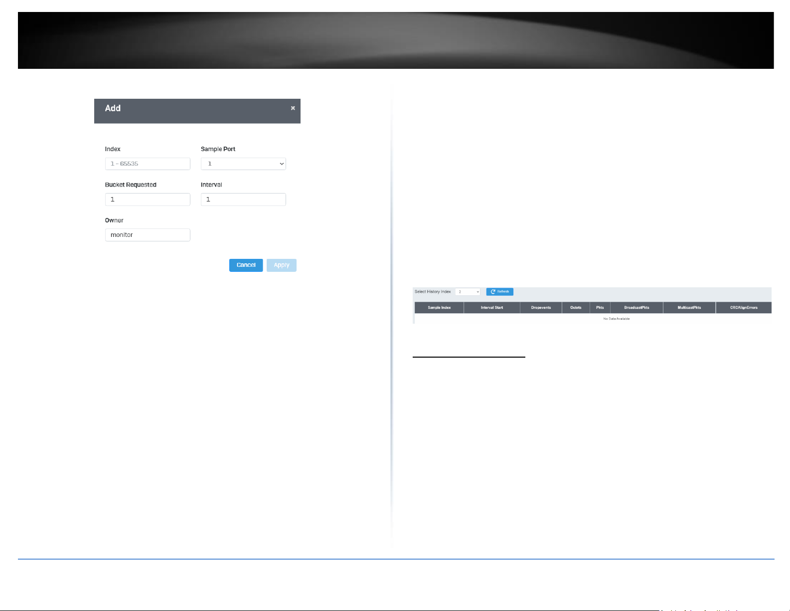
A history group is divided into buckets. Each bucket stores one snapshot of statistics of a
port. A group can have from 1 to 50 buckets. The more buckets in a group, the more
snapshots it can store.
1. Log into your switch management page (see “Access your switch management page”
on page 5).
2. Click on System, click on RMON, and click on History.
3. Review the settings.
• Index: This parameter specifies the ID number of the new group. The range is 1
to 65535.
• Sample Port: This parameter specifies the port where you want to monitor the
statistical information of the Ethernet traffic.
• Buckets Requested: This parameter defines the number of snapshots of the
statistics for the port. Each bucket can store one snapshot of RMON statistics.
Different ports can have different numbers of buckets. The range is 1 to 50
buckets.
• Interval: This parameter specifies how frequently the switch takes snapshots of
the port’s statistics. The range is 1 to 3600 seconds (1 hour). For example, if
you want the switch to take one snapshot every minute on a port, you specify
an interval of sixty seconds.
• Owner: This parameter is used to identify the person who created an entry. It is
primarily intended for switches that are managed by more than one person,
and is an optional field.
Click Add to add the entry to the table.
Page 37
© Copyright 2022 TRENDnet. All Rights Reserved.
23
TRENDnet User’s Guide
Multi-Gig Web Smart Switch Series
History Log Table
System > RMON > History Log Table
RMON History Logs are accessed from this section. RMON History logs can be filtered by
RMON Index.
1. Log into your switch management page (see “Access your switch management page”
on page 5).
2. Click on System, click on RMON, and click on History Log Table.
3. Select the History Index from the drop-down menu. Click the Refresh button if the
page needs to be refreshed.
MAC Address Table
Static MAC Address
System > MAC Address Table > Static MAC Address
1. Log into your switch management page (see “Access your switch management page”
on page 5).
2. Click on System, click on MAC Address Table, and click on Static MAC Address.
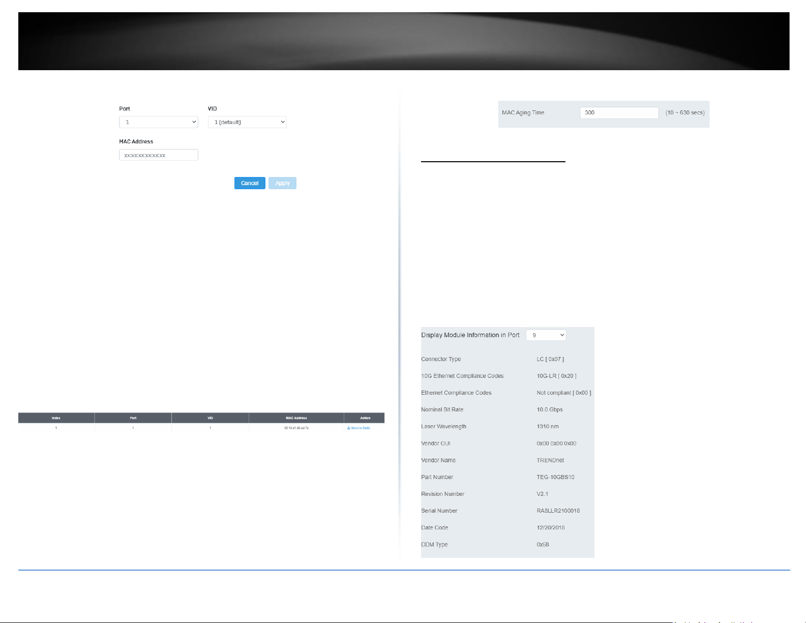
3. Click Add to configure a new static MAC address
4. Review the settings and click Apply.
Page 38
© Copyright 2022 TRENDnet. All Rights Reserved.
24
TRENDnet User’s Guide
Multi-Gig Web Smart Switch Series
• Port: Select the port where the MAC address will reside.
• VID: Select the VLAN ID where the MAC address will reside
Note By default, all switch ports are part of the default VLAN, VLAN ID 1
• MAC Address: Enter the MAC address of he device to add
Dynamic MAC Address
System > MAC Address Table > Dynamic MAC Address
1. Log into your switch management page (see “Access your switch management page”
on page 5).
2. Click on System, click on MAC Address Table, and click on Dynamic MAC Address.
3. The table currently displays the MAC address of devices connected to the switch. To
move a MAC address to Static MAC Address, click Move to Static
MAC Aging Time
System > MAC Address Table > MAC Aging Time
1. Log into your switch management page (see “Access your switch management page”
on page 5).
2. Click on System, click on MAC Address Table, and click on MAC Aging Time.
3. Enter the duration in seconds for MAC Aging Table
SFP Module Information
Module & DDM
1. Log into your switch management page (see “Access your switch management page”
on page 5).
2. Click on System, click on SFP Module Information , and select either Module or DDM.
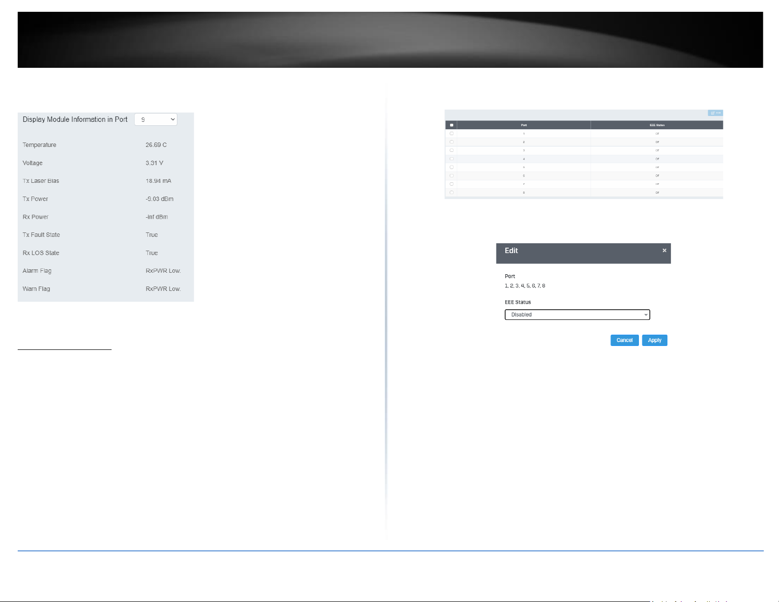
3. Module and DDM displays additional information of the SFP module that’s connected
in the SFP slots.
Module:
Page 39
© Copyright 2022 TRENDnet. All Rights Reserved.
25
TRENDnet User’s Guide
Multi-Gig Web Smart Switch Series
DDM:
IEEE 802.3az EEE
Enable IEEE 802.3az Power Saving Mode
System > EEE
The IEEE 802.3 EEE standard defines mechanisms and protocols intended to reduce the
energy consumption of network links during periods of low utilization, by transitioning
interfaces into a low-power state without interrupting the network connection. The
transmitted and received sides should be IEEE802.3az EEE compliance. By default, the
switch disabled the IEEE 802.3az EEE function. Users can enable this feature via the
IEEE802.3az EEE setting page.
1. Log into your switch management page (see “Access your switch management page”
on page 5).
2. Click on Tools and click on EEE.
3. Select the port you would like to turn on or off the IEEE 802.3az. To select all the
ports, click the box on the top left. Click Edit to modify the options.
4. Select Enable or Disabled from the drop down menu to turn on or turn off the IEEE
802.3az settings for the selected ports.
5. Click the Apply button to save the settings to the flash.
Note: This step saves all configuration changes to the NV-RAM to ensure that if the
switch is rebooted or power cycled, the configuration changes will still be applied.
Page 40

© Copyright 2022 TRENDnet. All Rights Reserved.
26
TRENDnet User’s Guide
Multi-Gig Web Smart Switch Series
Network
Physical Interface
Configure Physical Interfaces
Network > Physical Interface
This section allows you to configure the physical port parameters such as speed, duplex,
flow control, and jumbo frames. This section also reports the current link status of each
port and negotiated speed/duplex. Additionally you will be able to set your BPDU ports
for Spanning Tree Configuration and EAP ports for 802.1x port-based authentication
configuration.
1. Log into your switch management page (see “Access your switch management page”
on page 5).
2. Click on Network, click on Physical Interface, and click on Port.
3. Review the settings. Click Apply to save changes.
• Port - Specifies the port number. The All value indicates ports 1
through 10 on the Switch. You cannot change this parameter. You
can use the All column value in the Port column to apply, Mode,
Flow Control, and Description settings to all ports at the same
time.
• Link Status - This parameter indicates the status of the link
between the port and the end node connected to the port. The
possible values are:
• Link up -This parameter indicates a valid link exists between the
port and the end node.
• Link down -This parameter indicates the port and the end node
have not established a valid link.
• Mode: This parameter indicates the speed and duplex mode
settings for the port. You can use this parameter to set the speed
and duplex mode of a port. The possible settings are:
• Auto -This parameter indicates the port is using Auto-Negotiation
to set the operating speed and duplex mode. The actual operating
speed and duplex mode of the port are displayed in parentheses
(for example, “1000/F” for 1000 Mbps full duplex mode) after a
port establishes a link with an end node.
• Auto (1000F) -This parameter indicates the port is configured for
1000Mbps operation in Auto-Negotiation mode.
• 10G/Full – This parameter indicates the port is configured for
10Gbps operation in full-duplex mode
• 2.5G Full – This parameter indicates the port is configured for
2.5Gbps operation in full-duplex mode.
• 1000/Full -This parameter indicates the port is configured for
1000Mbps operation in full-duplex mode.
• 100/Full -This parameter indicates the port is configured for
100Mbps operation in full-duplex mode.
Note: When selecting a Mode setting, the following points apply:
• When a twisted-pair port is set to Auto-Negotiation, the end node
should also be set to Auto-Negotiation to prevent a duplex mode
mismatch.
• A switch port using Auto-Negotiation defaults to half-duplex if it
detects that the end node is not using Auto-Negotiation. This can
result in a mismatch if the end node is operating at a fixed duplex
mode of full-duplex. To avoid this problem when connecting an
end node with a fixed duplex mode of full-duplex to a switch port,
disable Auto-Negotiation on the port and set the port’s speed and
duplex mode manually.
• The only valid setting for the SFP ports is Auto-Negotiation.
• Flow Control: This parameter reflects the current flow control
setting on the port. The switch uses a special pause packet to
Page 41
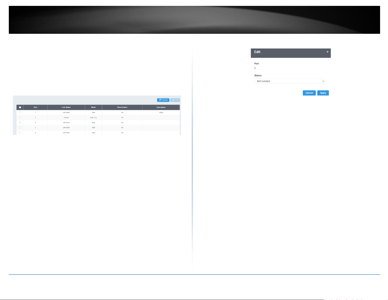
© Copyright 2022 TRENDnet. All Rights Reserved.
27
TRENDnet User’s Guide
Multi-Gig Web Smart Switch Series
notify the end node to stop transmitting for a specified period of
time. The possible values are:
• Enabled - This parameter indicates that the port is permitted to
use flow control.
• Disabled - This parameter indicates that the port is not permitted
to use flow control.
• Description: This parameter offers the ability to name the device
that’s connected to it
Port Isolation
Network > Physical Interface > Port Isolation
Port isolation prevents traffic from being sent between specific ports.
1. Log into your switch management page (see “Access your switch management page”
on page 5).
2. Click on Network, click on Physical Interface, and click on Port Isolation.
3. Select the port you would like to be edit. You may also select all ports by selecting All
column.
4. Select from the drop down menu to either Isolate or Not Isolate for the specified port
and click Apply to save your settings.
Note: This step saves all configuration changes to the NV-RAM to ensure that if the
switch is rebooted or power cycled, the configuration changes will still be applied.
Mirroring
Network > Physical Interface > Mirror
Port mirroring allows you to monitor the ingress and egress traffic on a port by having
the traffic copied to another port where a computer or device can be set up to capture
the data for monitoring and troubleshooting purposes.
1. Log into your switch management page (see “Access your switch management page”
on page 5).
2. Click on Network, then click on Physical Interface, and click on Mirror.
3. Review the settings. Click Apply to save changes.
• Edit – Click to edit the selected session ID.
• Session State – Click the drop-down and list and select one of the
following options:
• Enable - This parameter activates the Port Mirroring feature and
the rest of the configuration parameters become active on the
page.
• Disable - This parameter de-activates the Port Mirroring feature
and the rest of the configuration parameters become inactive on
the page.
Page 42
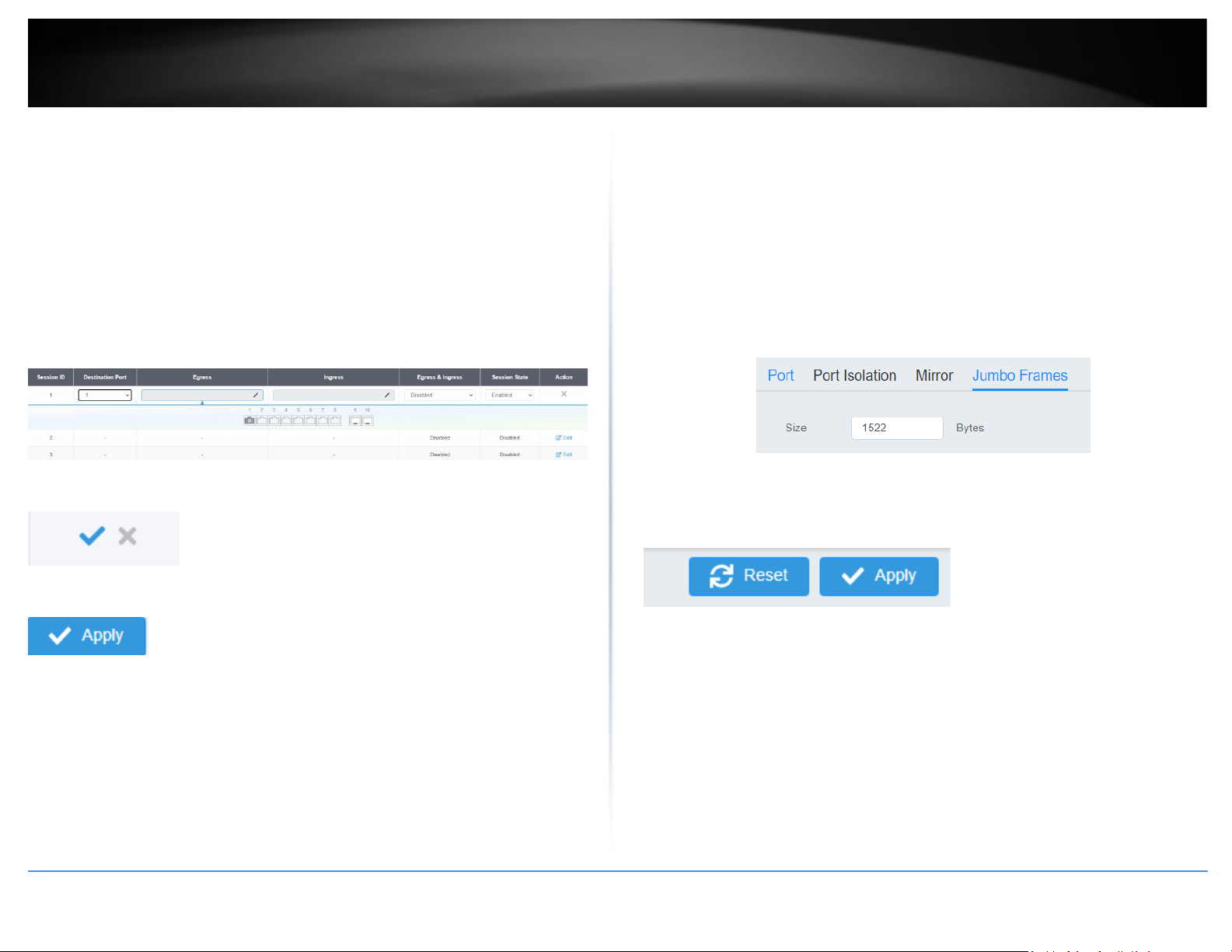
© Copyright 2022 TRENDnet. All Rights Reserved.
28
TRENDnet User’s Guide
Multi-Gig Web Smart Switch Series
• Destination Port – Click the drop-down and list and select the
port to send the copied ingress/egress packets/data. (e.g.
Computer or device with packet capture or data analysis
program.)
Check the port to monitor or copy inormation from. (Source)
To copy data received on a specific port, select the port number(s) under the Ingress
Port section or you could click All to copy data received on all ports.
To copy data transmitted on specific port, select the port number under the Egress Port
section or you could click All to copy data transmitted on all ports.
4. At the right hand panel, click the check mark to save your settings.
5. At the top right of the screen, click Apply.
Note: This step saves all configuration changes to the NV-RAM to ensure that if the
switch is rebooted or power cycled, the configuration changes will still be applied.
Jumbo Frames
Network > Physical Interface > Jumbo Frames
This section lets you input the size of the Jumbo Frames that can be accepted by the
switch.
1. Log into your switch management page (see “Access your switch management page”
on page 5).
2. Click on Network, then click on Physical Interface, and click on Jumbo Frames.
3. Enter the size of the Jumbo Frames to be accepted by the switch (in Bytes).
Note: The value of the Jumbo Frames needs to be between 1522 and 10240 Bytes. By
default the value is 1522 Bytes.
4. Click Reset to reset the size of the Jumbo Frames to its default value. To save your
new Jumbo Frame size, click Apply.
Note: This step saves all configuration changes to the NV-RAM to ensure that if the
switch is rebooted or power cycled, the configuration changes will still be applied.
Page 43
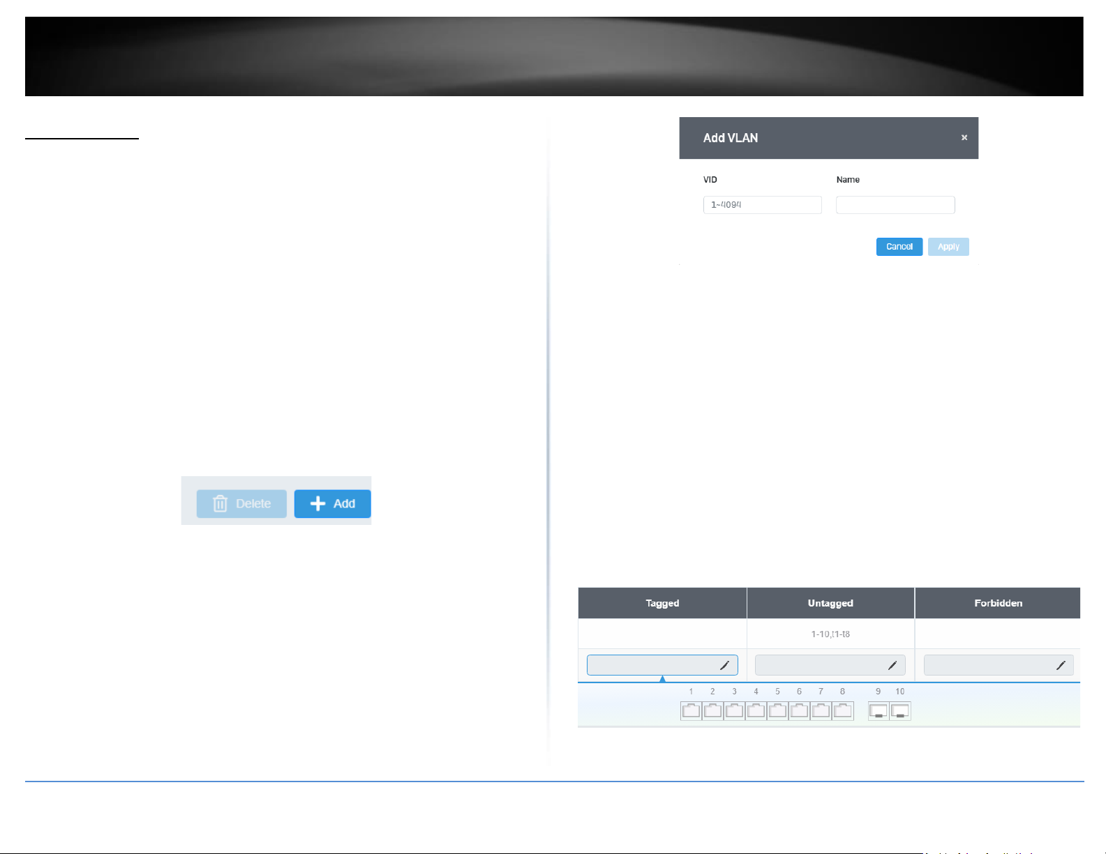
© Copyright 2022 TRENDnet. All Rights Reserved.
29
TRENDnet User’s Guide
Multi-Gig Web Smart Switch Series
VLAN Settings
802.1Q VLAN
Network > VLAN Settings > 802.1Q
A VLAN is a group of ports that can be anywhere in the network, but communicate as
though they were in the same area.
VLANs can be easily organized to reflect department groups (such as R&D, Marketing),
usage groups (such as e-mail), or multicast groups (multimedia applications such as
video conferencing), and therefore help to simplify network management by allowing
users to move devices to a new VLAN without having to change any physical
connections.
1. Log into your switch management page (see “Access your switch management page”
on page 5).
2. Click on Network, click on VLAN Settings, and click on 802.1Q.
3. Click on Add to create a new VLAN.
3. Review the settings.
• VID – Enter the VLAN ID for the new VLAN.
• Name – Enter the VLAN name.
Note: By default, the default VLAN VID 1 is set as the Management VLAN.
• Cancel – Deletes the current settings
• Apply – Apply the new settings
In the sections Static Tagged, Static Untagged, and Not Member, you can add the type
of VLAN ports to add to the new VLAN (Tagged or Untagged) and assign ports that are
not members (Forbidden) of the new VLAN.
Tagged/Untagged/Not Member VLAN Ports
On a port, the tag information within a frame is examined when it is received to
determine if the frame is qualified as a member of a specific tagged VLAN. If it is, it is
eligible to be switched to other member ports of the same VLAN. If it is determined that
the frame’s tag does not conform to the tagged VLAN, the frame is discarded.
Since these VLAN ports are VLAN aware and able to read VLAN VID tagged information
on a frame and forward to the appropriate VLAN, typically tagged VLAN ports are used
for uplink and downlink to other switches to carry and forward traffic for multiple VLANs
across multiple switches. Tagged VLAN ports can be included as members for multiple
VLANs. Computers and other edge devices are not typically connected to tagged VLAN
ports unless the network interface on these device can be enabled to be VLAN aware.
Select the tagged VLAN ports to add to the new VLAN.
Page 44
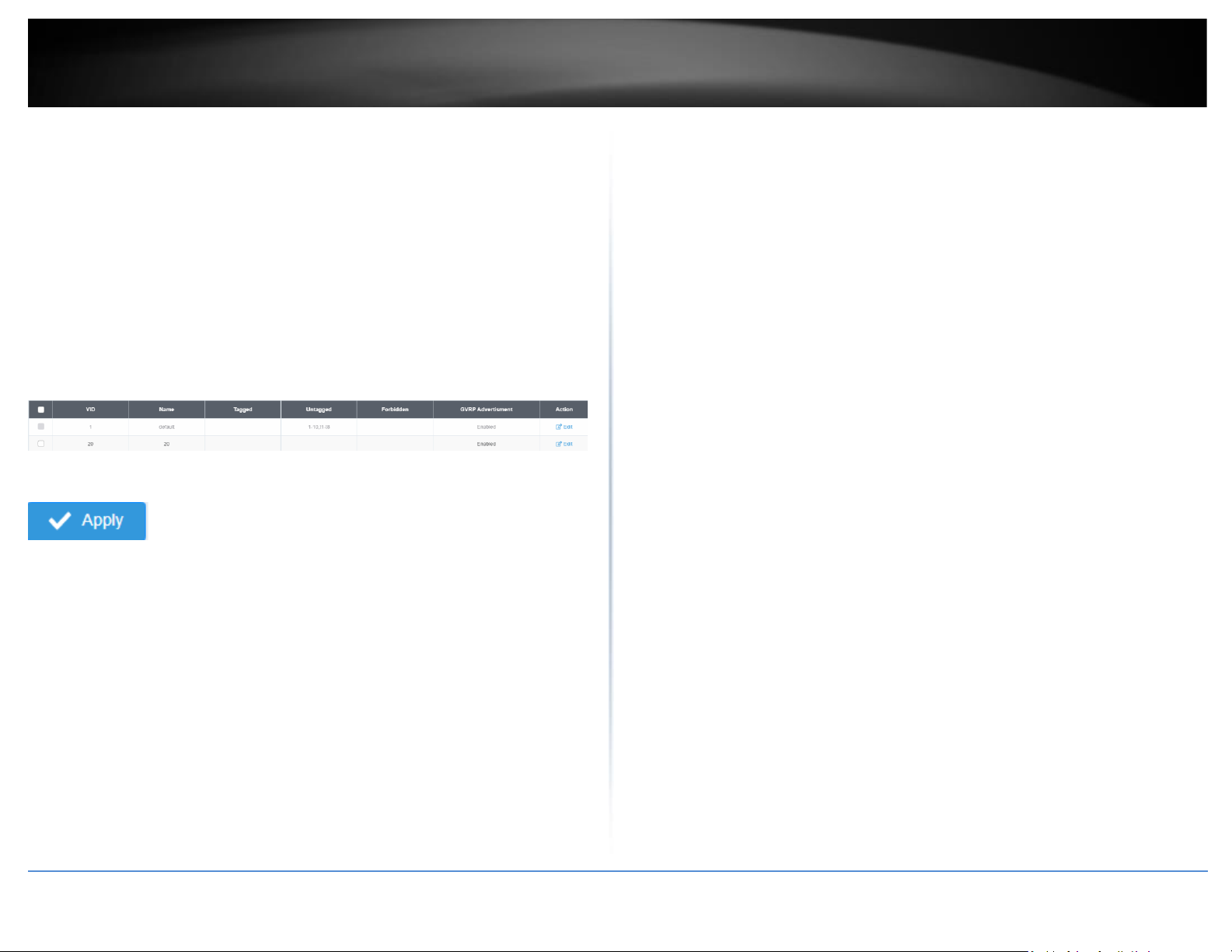
© Copyright 2022 TRENDnet. All Rights Reserved.
30
TRENDnet User’s Guide
Multi-Gig Web Smart Switch Series
Untagged VLAN ports are used to connect edge devices (VLAN unaware) such as
computers, laptops, and printers to a specified VLAN. It is required to modify the Port
VID settings accordingly for untagged VLAN ports under Bridge > VLAN > Port Settings.
(e.g. If the VID for the VLAN is 2, the PVID should also be set to 2)
Select the untagged VLAN ports to add to the new VLAN.
Select the Forbidden ports to restrict from the new VLAN.
Click Apply to save the new VLAN to the table.
In the list, you can click Edit to modify an entry
Note: The default VLAN VID1 cannot be removed.
4. At the top of the right hand panel, click Apply.
Note: This step saves all configuration changes to the NV-RAM to ensure that if the
switch is rebooted or power cycled, the configuration changes will still be applied
PVID & Ingress Filter
Network > VLAN Settings > PVID & Ingress Filter
In this section, you can modify the port VID settings, acceptable frame types, and
ingress filtering.
1. Log into your switch management page (see “Access your switch management page”
on page 5).
2. Click on Network, click on VLAN Settings, and click on PVID & Ingress Filter.
3. Select the port would like to modify and click Edit to modify an entry.
4. Review the settings for each port. Click Apply to save settings.
• Port – Displays the selected port
• PVID – Select the correct VLAN ID. Note: Required for untagged
VLAN ports.
• Ingress Filtering –Click the drop-down list and select Enabled to
enable ingress filtering or Disabled to disable ingress filtering.
• Acceptable Frame Type – Click the drop-down list and select
which type of frames can be accepted.
• All – The port can accept all frame types.
• Tagged – The port can accept tagged frames only. Untagged
frames are discarded.
• Untagged– The port can accept untagged frames and frames with
tagged priority information only such as 802.1p.
Note: Modifying settings in the row marked All, will apply the settings to all
ports.
Page 45
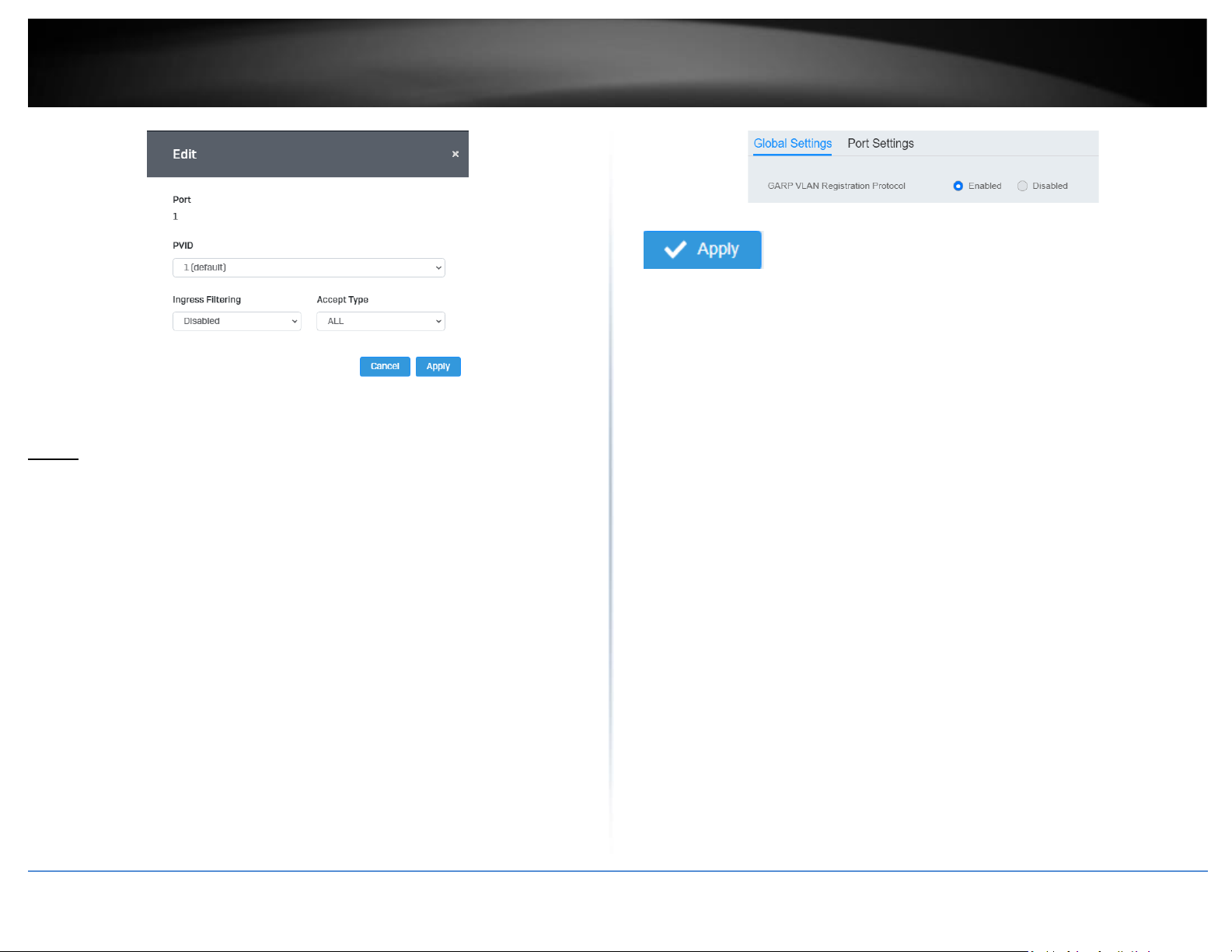
© Copyright 2022 TRENDnet. All Rights Reserved.
31
TRENDnet User’s Guide
Multi-Gig Web Smart Switch Series
4. At the bottom, click Apply to save the changes made.
GVRP
Protocol
Network > GVRP > Global Settings
The GVRP VLAN Registration Protocol (GVRP) allows network devices to share VLAN
information and to use the information to modify existing VLANs or create new VLANs,
automatically. This makes it easier to manage VLANs that span more than one switch.
Without GVRP, you have to manually configure your switches to ensure that the various
parts of the VLANs can communicate with each other across the different switches.
With GVRP, which is an application of the Generic Attribute Registration Protocol
(GARP), this is done for you automatically.
1. Log into your switch management page (see “Access your switch management page”
on page 5).
2. Click on Network, click on GVRP, and click on Global Settings.
3. Select Enabled under GARP VLAN Registration Protocol to to activate GVRP or
disabled to deactivate GVRP. Click Apply to save the settings.
4. At the top of the right hand panel, click Apply.
Note: This step saves all configuration changes to the NV-RAM to ensure that if the
switch is rebooted or power cycled, the configuration changes will still be applied.
Port Settings
Network > GVRP > Port Settings
This section will allow you to select which ports will have GVRP enabled or will be
restricted from using GVRP.
1. Log into your switch management page (see “Access your switch management page”
on page 5).
2. Click on Network, click on GVRP and click on Port Settings.
3. Select the port to modify the settings.
3. Review the settings for each port. Click Apply to save the settings.
• Port - This parameter displays the ports on the switch.
• JoinTime - This parameter is the GARP Join Timer. Its range is 10 - 4999000
milli-seconds.
• LeaveTime - This parameter is the GARP Leave Timer. Its range is 10 - 9999000
milli-seconds. This timer must be set in relation to the GVRP Join Timer
according to the following equation:
GARPLeaveTimer >= (GARPJoinTimer X 2) + 10
Page 46
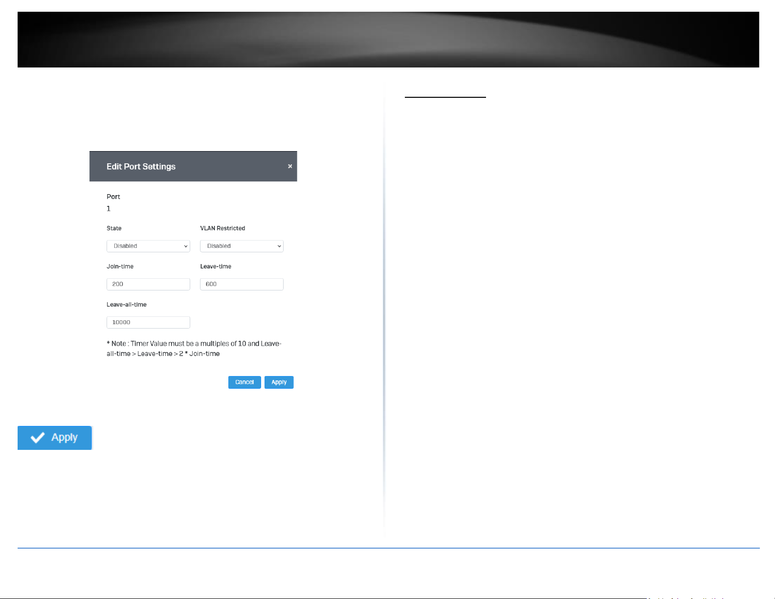
© Copyright 2022 TRENDnet. All Rights Reserved.
32
TRENDnet User’s Guide
Multi-Gig Web Smart Switch Series
• LeaveAllTime - This parameter is the GARP Leave All Timer. Its range is 10 -
10000000 milli-seconds. This timer must be set in relation to the GVRP Leave
Timer according to the following equation:
GARPLeaveAllTimer > (GARPLeaveTimer + 10)
4. At the bottom of the right hand panel, click Apply.
Note: This step saves all configuration changes to the NV-RAM to ensure that if the
switch is rebooted or power cycled, the configuration changes will still be applied
Spanning Tree
Protocol
Network > Spanning Tree > Global Settings > STP
Spanning Tree Protocol (STP) provides network topology for any arrangement of
bridges/switches. STP also provides a single path between end stations on a network,
eliminating loops. Loops occur when alternate routes exist between hosts. Loops in an
extended network can cause bridges to forward traffic indefinitely, resulting in
increased traffic and reducing network efficiency.
1. Log into your switch management page (see “Access your switch management page”
on page 5).
2. Click on Network, click on Spanning Tree, click on Global Settings, and click on STP.
3. Review the settings. Click Apply to save changes.
• STP State: Select Enabled to Enable Spanning Tree Protocol, or Disabled to
disable STP.
• Force Version: Select MSTP or RSTP from the drop-down menu
• Configuration Name: Name the current STP
• Configuration Revision: Assign a revision number
• Priority: The Priority has a range 0 to 61440 in increments of 4096. To make
this easier for you, the Web Management Utility divides the range into
increments. You specify the increment that represents the desired bridge
priority value.
• Forward Delay: The Forward Delay defines the time that the bridge spends in
the listening and learning states. Its range is 4 - 30 seconds.
• Maximum Age: The Maximum Age defines the amount of time a port will wait
for STP/RSTP information. MSTP uses this parameter when interacting with
STP/RSTP domains on the boundary ports. Its range is 6 - 40 seconds
• TX Hold Count: The Transmit Hold Count specifies the maximum number of
BPDUs that the bridge can send per second. Its range is 1 - 10.
• Hello Time: The Hello Time is frequency with which the root bridge sends out a
BPDU.
Page 47
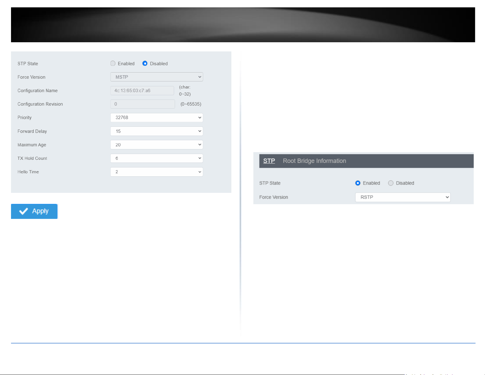
© Copyright 2022 TRENDnet. All Rights Reserved.
33
TRENDnet User’s Guide
Multi-Gig Web Smart Switch Series
4. At the top right panel, click Apply.
Note: This step saves all configuration changes to the NV-RAM to ensure that if the
switch is rebooted or power cycled, the configuration changes will still be applied
Root Bridge Information
Network > Spanning Tree > Global Settings > Root Bridge Information
1. Log into your switch management page (see “Access your switch management page”
on page 5).
2. Click on Network, click on Spanning Tree, click on Global Settings, and click on Root
Bridge Information.
3. Displays the current settings made under STP.
RSTP Port Settings
Network > Spanning Tree > RSTP Port Settings
1. Log into your switch management page (see “Access your switch management page”
on page 5).
2. Click on Network, click on Spanning Tree, click on Global Settings, and click on STP.
3. Select RSTP from the drop down menu on Force Version
4. Click on RSTP Port Settings and select the port(s) to configure and click Edit.
5. Review the settings and click Apply to save your changes.
Page 48
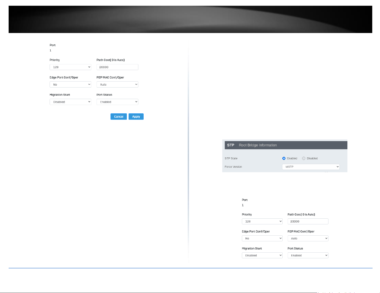
© Copyright 2022 TRENDnet. All Rights Reserved.
34
TRENDnet User’s Guide
Multi-Gig Web Smart Switch Series
• Priority: Indicates the port priority. If two paths have the same port cost, the
bridges must select a preferred path. In some instances this can involve the use of the
port priority parameter which is used as a tie breaker when two paths have the same
cost. The range for port priority is 0 to 240. As with bridge priority, this range is broken
into increments, in this case multiples of 16. To select a port priority for a port, you
enter the desired value. Table 1 lists the values that are valid.
• Path Cost: This defines a metric that indicates the relative cost of forwarding
packets to the specified port list. Port cost can be set automatically or as a metric value.
Define a value between 1 and 200000000 to determine the external cost. The lower the
number, the greater the probability the port will be chosen to forward packets. The
default port cost: 100Mbps port = 200000. Gigabit port = 20000.
• Edge Port Conf/Oper: Indicates if a port is connected to an edge device in the
network topology or not. Select Yes designates the port is an edge port, and No to
designate the port is not an edge port.
• P2P MAC Conf/Oper: P2P ports are similar to edge ports, however, they are
restricted in that a P2P port must operate in full-duplex. Auto allows the port to have
P2P status whenever possible and operate as if the P2P status were true. Selecting Yes
indicates a P2P shared link is available. Selecting No means the port cannot maintain a
P2P link.
• Migration: Enabled indicates the port is configured to accept RSTP and
Disabled indicates the port is not configured to accept RSTP.
• Status: Select Enabled to enable the status to be shown or Disabled to disable
this feature.
CIST Port Settings
Network > Spanning Tree > CIST Port Settings
1. Log into your switch management page (see “Access your switch management page”
on page 5).
2. Click on Network, click on Spanning Tree, click on Global Settings, and click on STP.
3. Select MSTP from the drop down menu on Force Version
4. Click on Cist Port Settings and select the port(s) to configure and click Edit.
5. Review the settings and click Apply to save your changes.
Page 49
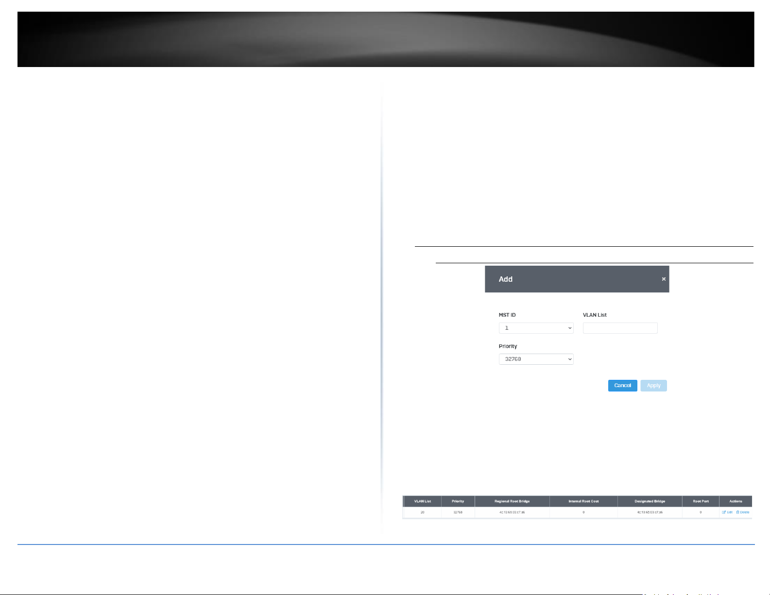
© Copyright 2022 TRENDnet. All Rights Reserved.
35
TRENDnet User’s Guide
Multi-Gig Web Smart Switch Series
• Priority: Indicates the port priority. If two paths have the same port cost, the
bridges must select a preferred path. In some instances this can involve the use of the
port priority parameter which is used as a tie breaker when two paths have the same
cost. The range for port priority is 0 to 240. As with bridge priority, this range is broken
into increments, in this case multiples of 16. To select a port priority for a port, you
enter the desired value. Table 1 lists the values that are valid.
• Path Cost: This defines a metric that indicates the relative cost of forwarding
packets to the specified port list. Port cost can be set automatically or as a metric value.
Define a value between 1 and 200000000 to determine the external cost. The lower the
number, the greater the probability the port will be chosen to forward packets. The
default port cost: 100Mbps port = 200000. Gigabit port = 20000.
• Edge Port Conf/Oper: Indicates if a port is connected to an edge device in the
network topology or not. Select Yes designates the port is an edge port, and No to
designate the port is not an edge port.
• P2P MAC Conf/Oper: P2P ports are similar to edge ports, however, they are
restricted in that a P2P port must operate in full-duplex. Auto allows the port to have
P2P status whenever possible and operate as if the P2P status were true. Selecting Yes
indicates a P2P shared link is available. Selecting No means the port cannot maintain a
P2P link.
• Migration: Enabled indicates the port is configured to accept RSTP and
Disabled indicates the port is not configured to accept RSTP.
• Status: Select Enabled to enable the status to be shown or Disabled to disable
this feature.
MST
Network > Spanning Tree > MST Instance Settings
1. Log into your switch management page (see “Access your switch management page”
on page 5).
2. Click on System, click on Spanning Tree, and click on MST Instance Settings.
3. Click on Add to add a new entry.
4. Review the settings. For each section, click Apply to save changes.
MST Configuration Identification Settings
• Configuration Name: A configured name set on the switch to uniquely identify
the MSTI (Multiple Spanning Tree Instance). If a configuration name is not set, this field
shows the MAC address of the device running MSTP.
• Revision Level (0-65535): This value, together with the configuration name,
and identical vlans mapped for STP instance IDs identifies the MST region
configured on the switch.
MST Instance Settings
• MSTI ID: Displays the MST ID associated with the VID List. The possible field
range is 1-4.
• VLAN List: Displays the VID List.
• Priority: Select the new priority in the Priority field from the drop down menu
options. The user may set a priority value between 0-61440.
Page 50
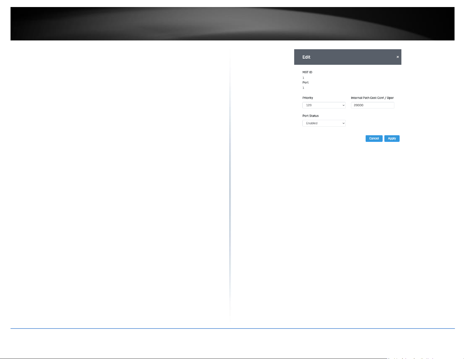
© Copyright 2022 TRENDnet. All Rights Reserved.
36
TRENDnet User’s Guide
Multi-Gig Web Smart Switch Series
• MST Table: Make changes to the table entry, and click Edit modify or click
Delete to remove the ID entry.
MST Port Settings
Network > Spanning Tree > MST Port Settings
1. Log into your switch management page (see “Access your switch management page”
on page 5).
2. Click on Network, click on Spanning Tree, and click on MST Port Settings.
3. Review the settings. For each entry, click Apply to save changes.
• Select MST Port – Select the MST Port to configure and click the Edit button.
• MST ID: The MST ID that is associated with this port
• MST Port Info - The MST Port Information page provides user to configure the
MSTP Interface settings.
• Priority - This is the port priority used by MSTP in calculating path costs when
two ports on the switch have the same port cost.
• Internal Path Cost (0 = Auto) - This is the port cost used by MSTP when
calculating path cost to the root bridge.
• Port Status: Enable or disable the current settings configured for the selected
port.
4. Click the Apply button to save the settings to the Flash.
Note: This step saves all configuration changes to the NV-RAM to ensure that if the
switch is rebooted or power cycled, the configuration changes will still be applied.
Page 51
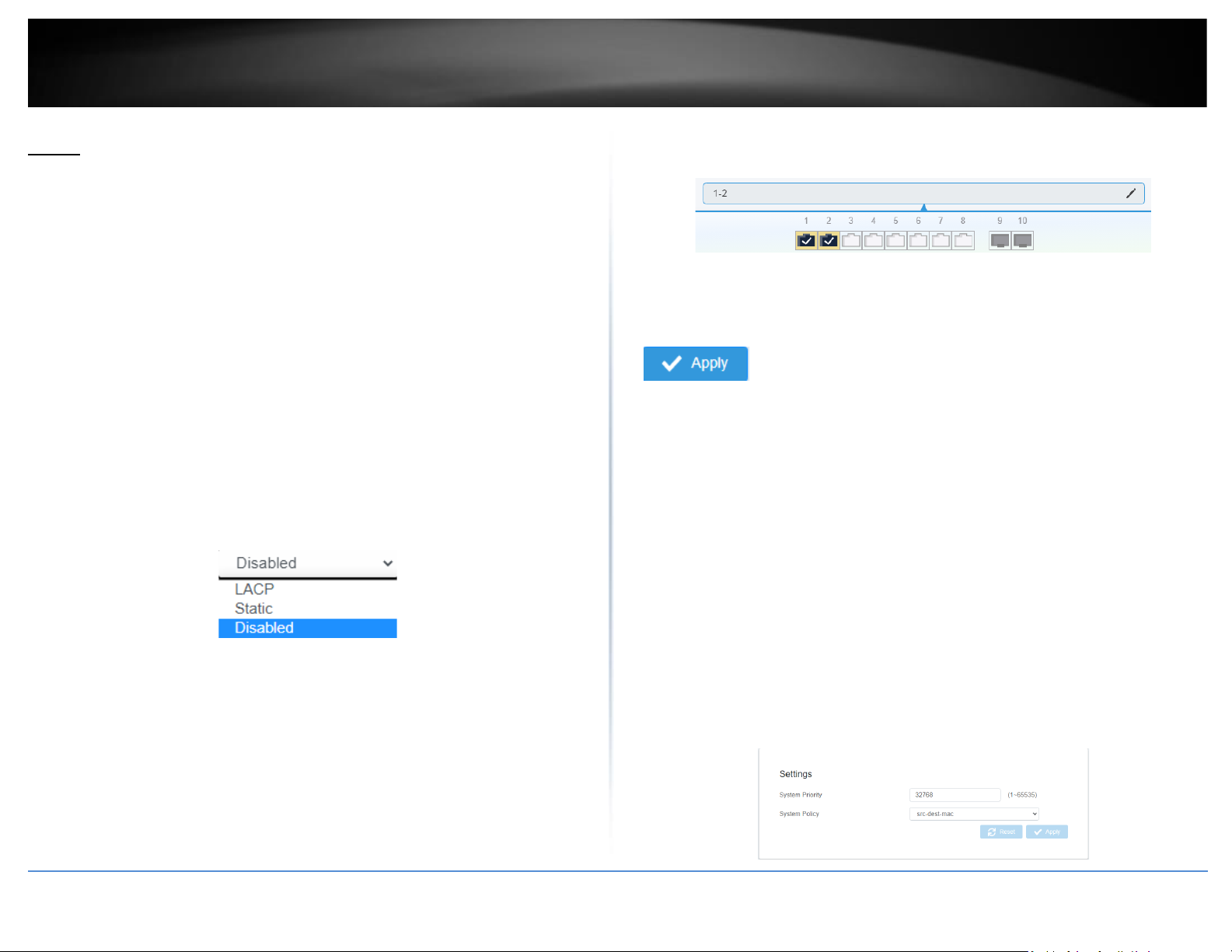
© Copyright 2022 TRENDnet. All Rights Reserved.
37
TRENDnet User’s Guide
Multi-Gig Web Smart Switch Series
Trunk
The trunking function enables the cascading of two or more ports for a combined larger
total bandwidth. Up to 8 trunk groups may be created, each supporting up to 8 ports.
Add a trunking Name and select the ports to be trunked together, and click Apply to
activate the selected trunking groups.
Important Note: Do not connect the cables of a port trunk to the ports on the switch
until you have configured the ports on both the switch and the end nodes. Connecting
the cables prior to configuring the ports can create loops in your network topology.
Loops can result in broadcast storms which can severely limited the effective bandwidth
of your network.
Settings
Network > Trunking
1. Log into your switch management page (see “Access your switch management page”
on page 5).
2. Click on Network, and click on Trunking.
3. Review the settings. For each trunk group, click Apply to save changes.
Click the drop-down list and select one of the following options.
• LACP - The specific aggregator will broadcast and respond to LACPDU (LACP
Data Unit) packets. This setting enables the dynamic LACP feature for the trunk.
• Static - Enables static port trunking and disables the LACP feature for the trunk.
(Static link aggregation).
• Disable - Disables the static port trunk and disables the LACP feature.
For each Trunk ID/Group, check the port numbers to add for each trunk group.
4. At the right hand of the group, click the check mark to apply the settings and the x
button to discard the settings.
5. Select the Apply button on the top left of the screen to save your settings to the flash.
Note: This step saves all configuration changes to the NV-RAM to ensure that if the
switch is rebooted or power cycled, the configuration changes will still be applied.
LACP
Network > Trunking > LACP
1. Log into your switch management page (see “Access your switch management page”
on page 5).
2. Click on Network, click on Trunk, and click on LACP.
3. Review the settings. Click Apply to save changes.
To assign a higher priority within a trunk group, input the priority value 1-65535 (65535
being the highest priority).
Page 52
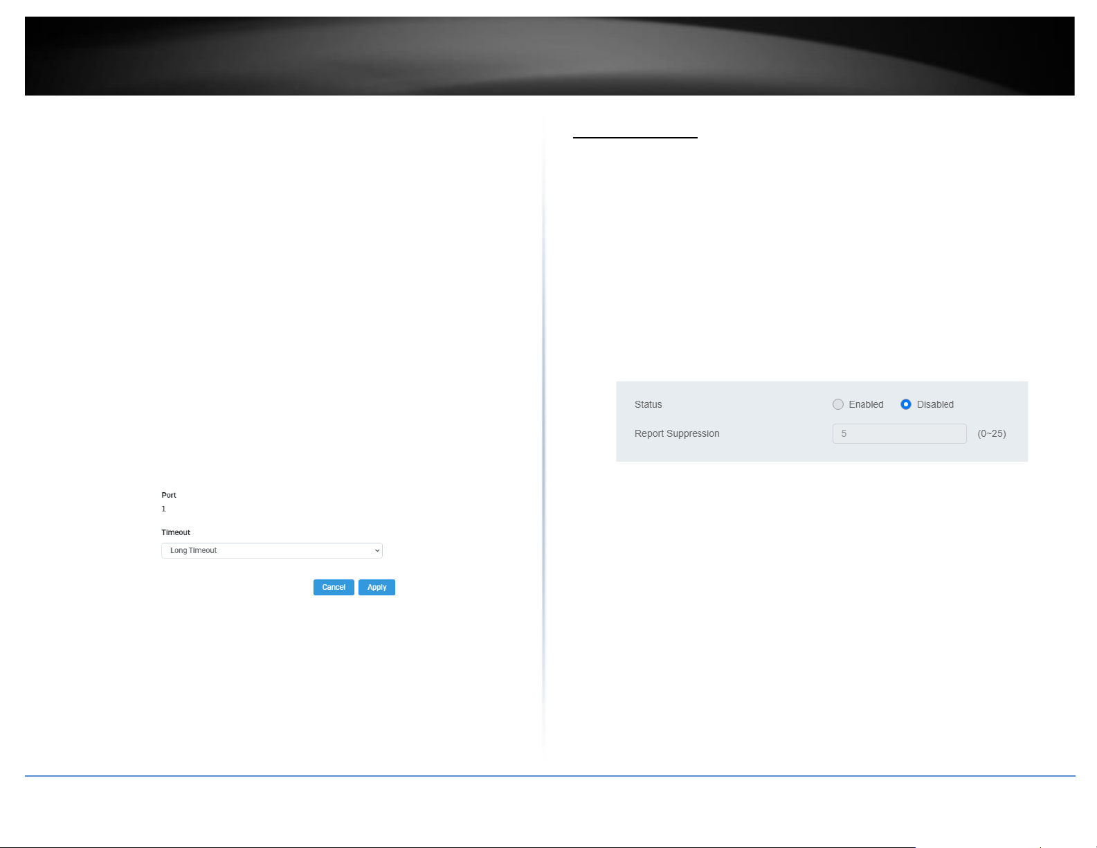
© Copyright 2022 TRENDnet. All Rights Reserved.
38
TRENDnet User’s Guide
Multi-Gig Web Smart Switch Series
4. Click Apply to save your settings to the flash.
Note: This step saves all configuration changes to the NV-RAM to ensure that if the
switch is rebooted or power cycled, the configuration changes will still be applied.
LACP Timeout
Network > Trunking > LACP
1. Log into your switch management page (see “Access your switch management page”
on page 5).
2. Click on Network, click on Trunk, and click on LACP.
3. Select the port to modify the settings and click Edit.
4. Select Long Timeout to configure the LACP timeout value to be 30 seconds, or Short
Timeout to configure the LACP timeout value to be 1 second.
4. Click Apply to save your settings to the flash.
Note: This step saves all configuration changes to the NV-RAM to ensure that if the
switch is rebooted or power cycled, the configuration changes will still be applied.
IGMP Snooping
Global Settings
Network > IGMP Snooping > Global Settings
1. Log into your switch management page (see “Access your switch management page”
on page 5).
2. Click on Network, click on IGMP Snooping, and click on Global Settings.
3. Review the settings. Click Apply to save the settings.
• Status – Select Enabled to enable the IGMP snooping feature or
Disabled to disable the feature.
• Report Suppression – Enter the time suppression interval
between 0 – 25.
Fast Leave
Network > IGMP Snooping > Port Settings
1. Log into your switch management page (see “Access your switch management page”
on page 5).
2. Click on Network, click on IGMP Snooping, and click on Port Settings.
3. Review the settings. Click Apply to save the settings.
•
Fast Leave – Select Enabled to enable Fast Leave from the selected port or
Disabled to disable the feature
Page 53
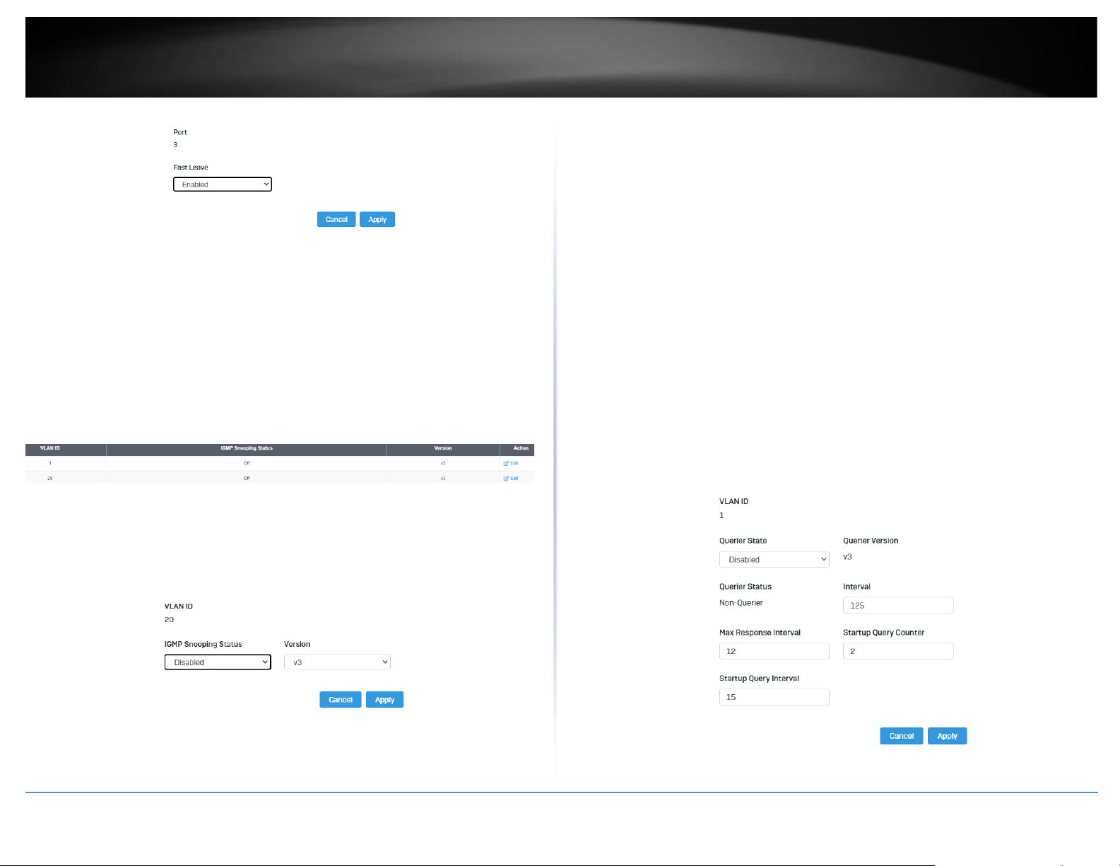
© Copyright 2022 TRENDnet. All Rights Reserved.
39
TRENDnet User’s Guide
Multi-Gig Web Smart Switch Series
VLAN Settings
Network > IGMP Snooping > VLAN Settings
1. Log into your switch management page (see “Access your switch management page”
on page 5).
2. Click on Network, click on IGMP Snooping, and click on VLAN Settings.
3. Select the VLAN ID to configure
4. Review the settings. Click Apply to save the settings.
•
IGMP Snooping Status – Click the drop-down list and select Enabled to enable
the IGMP snooping or Disabled to disable the feature
•
Version – Click the drop-down list and select IGMP version
Querier Settings
Network > IGMP Snooping > Querier Settings
1. Log into your switch management page (see “Access your switch management page”
on page 5).
2. Click on Network, click on IGMP Snooping, and click on Querier Settings.
3. Select the VLAN ID to configure
4. Review the settings. Click Apply to save the settings.
• Querier State – Click the drop-down list and select Enabled to
enable the Querier Status or Disabled to disable this feature.
• Interval – Enter the amount of time you want your switch to send
IGMP queries.
• Max Response Interval- Specifies the maximum time before
sending a response report.
• Startup Query Counter – Enter the amount to start the query
counter
• Startup Query Interval – Enter the amount of time to start the
query counter
Page 54
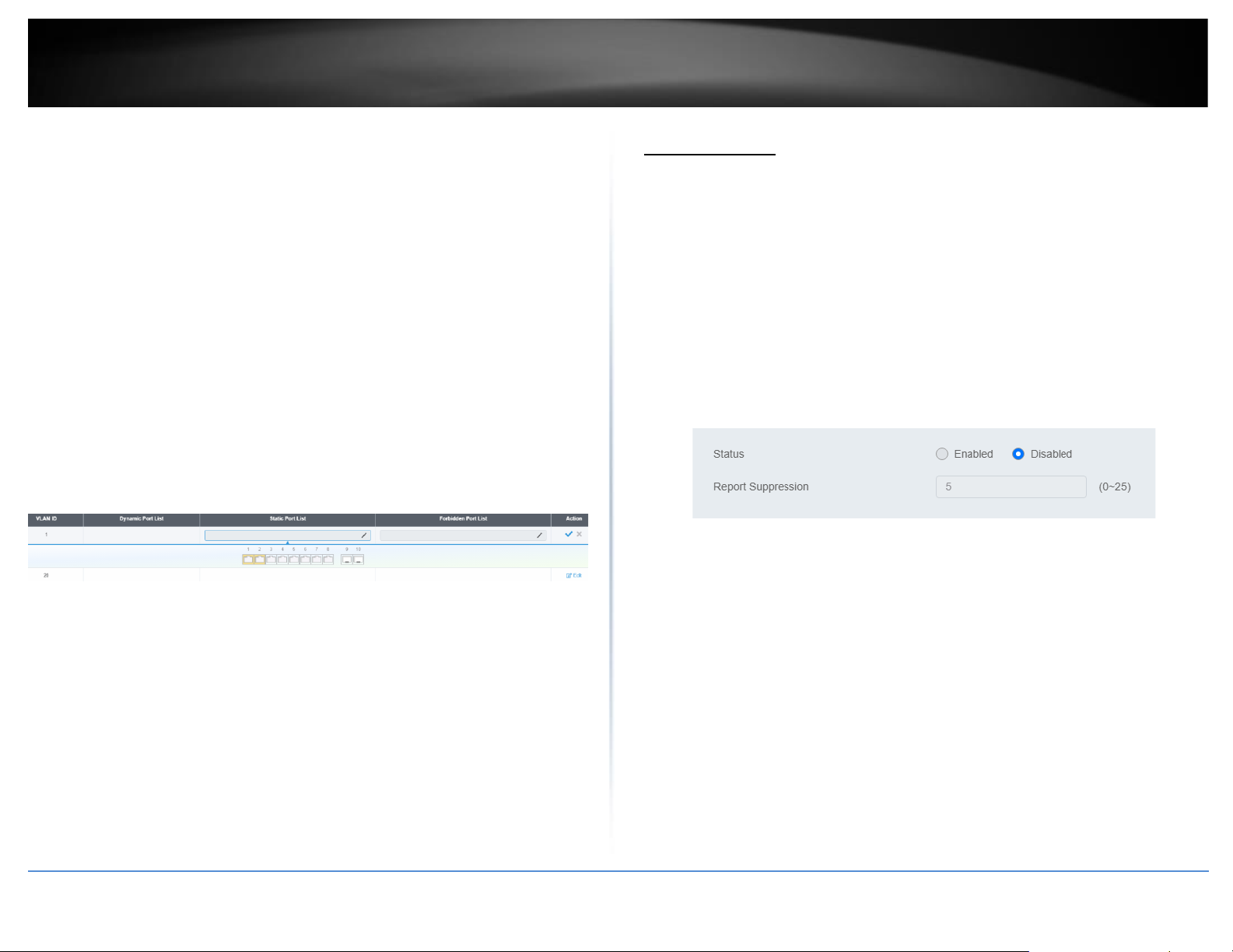
© Copyright 2022 TRENDnet. All Rights Reserved.
40
TRENDnet User’s Guide
Multi-Gig Web Smart Switch Series
Router Settings
Network > IGMP Snooping > Router Settings
1. Log into your switch management page (see “Access your switch management page”
on page 5).
2. Click on Network, click on IGMP Snooping, and click on Router Settings.
3. Select the VLAN ID to configure
4. Review the settings. Click Check Mark to save the settings.
4 Click the Static Port List and select the ports you would like to
statically assign
5 Click the Forbidding Port List and select the ports you would like
to assign to the Forbidden List
MLD Snooping
Global Settings
Network > MLD Snooping > Global Settings
1. Log into your switch management page (see “Access your switch management page”
on page 5).
2. Click on Network, click on MLD Snooping, and click on Global Settings.
3. Review the settings. Click Apply to save the settings.
• Status – Select Enabled to enable the MLD snooping feature or
Disabled to disable the feature.
• Report Suppression – Enter the time suppression interval
between 0 – 25.
Fast Leave
Network > MLD Snooping > Port Settings
1. Log into your switch management page (see “Access your switch management page”
on page 5).
2. Click on Network, click on MLD Snooping, and click on Port Settings.
3. Review the settings. Click Apply to save the settings.
•
Fast Leave – Select Enabled to enable Fast Leave from the selected port or
Disabled to disable the feature
Page 55
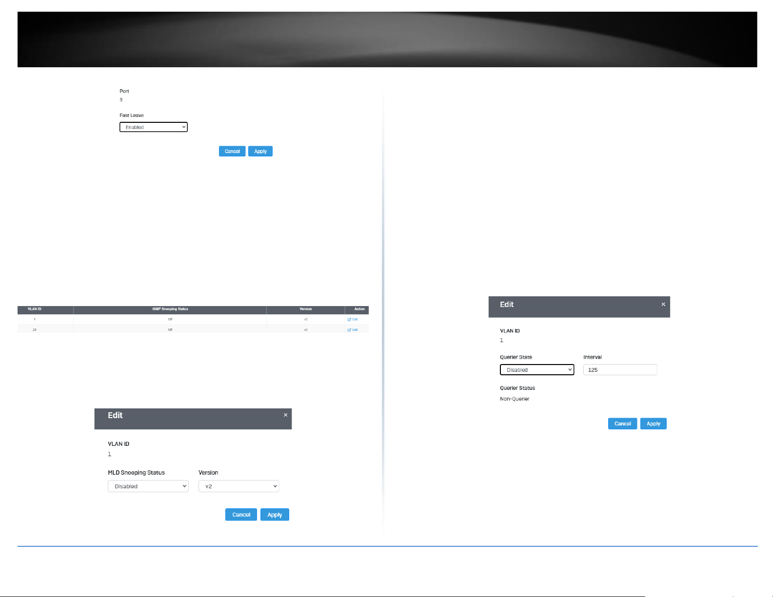
© Copyright 2022 TRENDnet. All Rights Reserved.
41
TRENDnet User’s Guide
Multi-Gig Web Smart Switch Series
VLAN Settings
Network > IGMP Snooping > VLAN Settings
1. Log into your switch management page (see “Access your switch management page”
on page 5).
2. Click on Network, click on MLD Snooping, and click on VLAN Settings.
3. Select the VLAN ID to configure
4. Review the settings. Click Apply to save the settings.
•
MLD Snooping Status – Click the drop-down list and select Enabled to enable
the IGMP snooping or Disabled to disable the feature
•
Version – Click the drop-down list and select IGMP version
Querier Settings
Network > MLD Snooping > Querier Settings
1. Log into your switch management page (see “Access your switch management page”
on page 5).
2. Click on Network, click on MLD Snooping, and click on Querier Settings.
3. Select the VLAN ID to configure
4. Review the settings. Click Apply to save the settings.
• Querier State – Click the drop-down list and select Enabled to
enable the Querier Status or Disabled to disable this feature.
• Interval – Enter the amount of time you want your switch to send
IGMP queries.
Router Settings
Network > MLD Snooping > Router Settings
1. Log into your switch management page (see “Access your switch management page”
on page 5).
Page 56
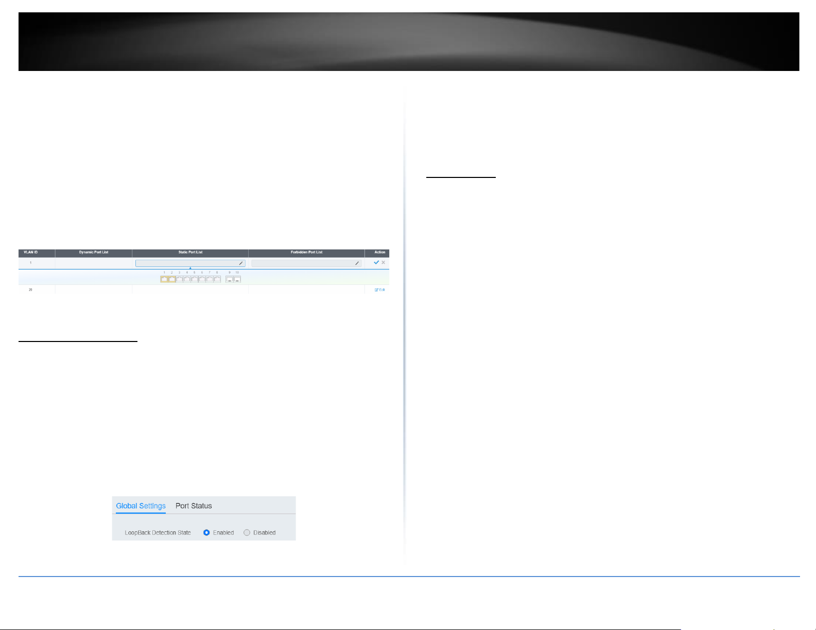
© Copyright 2022 TRENDnet. All Rights Reserved.
42
TRENDnet User’s Guide
Multi-Gig Web Smart Switch Series
2. Click on Network, click on MLD Snooping, and click on Router Settings.
3. Select the VLAN ID to configure
4. Review the settings. Click Check Mark to save the settings.
6 Click the Static Port List and select the ports you would like to
statically assign
7 Click the Forbidding Port List and select the ports you would like
to assign to the Forbidden List
Loopback Detection
Global Settings
Network > Loopback Detection > Global Settings
1. Log into your switch management page (see “Access your switch management page”
on page 5).
2. Click on Network, click on Loopback Detection, and click on Global Settings.
3. Select Enabled to enable loopback detection, or Disabled to disable this feature
4. At the top right panel, click the Apply button to save the changes to the Flash.
Note: This step saves all configuration changes to the NV-RAM to ensure that if the
switch is rebooted or power cycled, the configuration changes will still be applied
Voice VLAN
This chapter contains a description of the Switch’s Voice VLAN feature and the
procedures to create, modify, and delete a voice VLAN configuration.
The Voice VLAN feature is specifically designed to maintain high quality, uninterrupted
voice traffic through the switch. When talking on a voice over IP phone, a user expects
to have no interruptions in the conversation and excellent voice quality. The Voice VLAN
feature can be configured to meet these requirements.
CoS with Voice VLAN
The Voice VLAN CoS parameter maintains the voice quality between the ingress and
egress ports of the switch. CoS must be enabled for the Voice VLAN CoS priority to take
effect. The CoS priority level that you config is applied to voice traffic on all ports of the
voice VLAN. Normally, most (non-Voice) Ethernet traffic transverses the switch through
lower order egress queues. To avoid delays and interruptions in the voice data flow, the
CoS priority level assigned to the voice VLAN should be mapped to a higher order queue
and the scheduling algorithm should be set to Strict Priority. These settings ensure that
the voice data packets are processed before other types of data so that the voice quality
is maintained as the voice data passes through the switch.
Organization Unique Identifier (OUI)
Each IP phone manufacturer can be identified by one or more Organization Unique
Identifiers (OUIs). An OUI is three bytes long and is usually expressed in hexadecimal
format. It is imbedded into the first part of each MAC address of an Ethernet network
device. You can find the OUI of an IP phone in the first three complete bytes of its MAC
address.
Typically, you will find that all of the IP phones you are installing have the same OUI in
common. The switch identifies a voice data packet by comparing the OUI information in
the packet’s source MAC address with an OUI table that you configure when you initially
Page 57

© Copyright 2022 TRENDnet. All Rights Reserved.
43
TRENDnet User’s Guide
Multi-Gig Web Smart Switch Series
set up the voice VLAN. This is important when the Auto-Detection feature for a port and
is a dynamic voice VLAN port.
When you are configuring the voice VLAN parameters, you must enter the complete
MAC address of at least one of your IP phones. An “OUI Mask” is automatically
generated and applied by the Web Management Utility software to yield the
manufacturer’s OUI. If the OUI of the remaining phones from that manufacturer is the
same, then no other IP phone MAC addresses need to be entered into the configuration.
However, it is possible that you can find more than one OUI from the same
manufacturer among the IP phones you are installing. It is also possible that your IP
phones are from two or more different manufacturers in which case you will find
different OUIs for each manufacturer. If you identify more than one OUI among the IP
phones being installed, then one MAC address representing each individual OUI must be
configured in the voice VLAN. You can enter a total of 10 OUIs.
Dynamic Auto-Detection vs Static Ports
Prior to configuring the voice VLAN, you must configure a tagged VLAN which is the
basis for the voice VLAN configuration. The VLAN must be configured with one or more
tagged or untagged ports that will serve as the voice VLAN uplink/downlink. By default,
a tagged or untagged port is a static member of a tagged VLAN. The ports that you
choose to configure as dynamic Auto-Detection ports
must be connected directly to an IP phone. When you initially define the ports of a
tagged VLAN for your voice VLAN configuration, they must be configured as a “Not
Member” ports. The “Not Member” ports are eligible to dynamically join the voice VLAN
when voice data is detected with a predefined OUI in the source MAC address. The port
will leave the voice VLAN after a specified timeout period. This port behavior is
configured with the voice VLAN Auto-Detection feature.
For the Auto-Detection feature to function, your IP phone(s) must be capable of
generating 802.1Q packets with imbedded VLAN ID tags. You must manually configure
your IP phone(s) for the same VLAN ID as the switch’s voice VLAN ID. When voice data is
detected on one of the “Not Member” ports, the packets from the IP phone will contain
the voice VLAN ID so they are switched within the switch’s voice VLAN.
One or more ports in your voice VLAN must be configured as Static tagged or untagged
members. Static VLAN members are permanent member ports of the voice VLAN and
there is no dependency on the configuration of the devices connected to the ports.
These ports might be connected to other voice VLAN network nodes such as other
Ethernet switches, a telephone switch, or a DHCP server. The voice VLAN AutoDetection feature cannot be enabled on Static tagged or tagged ports.
Note: Any Static tagged members of the voice VLAN are required to have the port VLAN
ID (PVID) configured to be the same as the voice VLAN ID. This insures that all untagged
packets entering the port are switched within the voice VLAN as the voice data passes
through the switch.
If the IP phone(s) that you are installing cannot be configured with a VLAN ID, then the
switch ports should be configured as Static tagged ports within the voice VLAN.
Note: Link Layer Discovery Protocol for Media Endpoint Devices (LLDP- MED) is not
supported on the switch. Each IP phone that is VLAN aware should be manually
configured for the VLAN ID that matches your voice VLAN ID. Each of the voice VLAN
ports connected to an IP phone should be configured as “Not Member” ports of the
tagged VLAN.
Global Settings
Network > Voice VLAN > Global Settings
Note: Prior to configuring your voice VLAN, you must first configure a tagged VLAN. This
VLAN will be used as a basis for your voice VLAN.
1. Log into your switch management page (see “Access your switch management page”
on page 5).
2. Click on Network, click on Voice VLAN, and click on Global Settings.
3. Review the settings.
Use the following procedure to configure voice VLAN:
• Voice VLAN State – Select Disabled to disable this feature, or
Auto to allow this feature to be automatically enable and disable
or set it to OUI to use pre-selected OUI VLANs
• Voice VLAN ID - This parameter is the tagged VLAN ID that has
been configured in “Tagged VLAN Configuration”. It is a pull-down
menu showing the tagged VLAN IDs that have been defined.
• VLAN Priority Tag – This parameter sets the priority of the VLAN.
The priority is configured through the pull-down menu.
Page 58
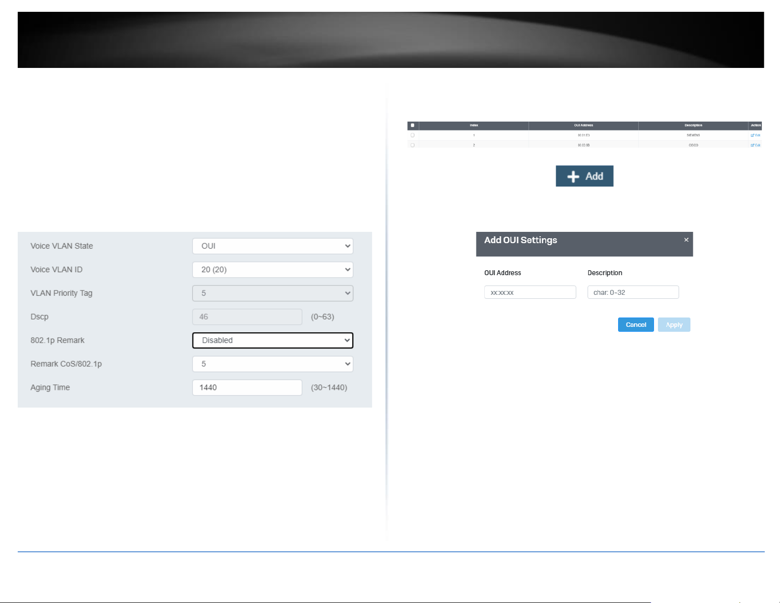
© Copyright 2022 TRENDnet. All Rights Reserved.
44
TRENDnet User’s Guide
Multi-Gig Web Smart Switch Series
• DSCP: Configure the DSCP for your switch. The range is from 0-63.
• 802.1p Remark – Enable 802.1p QoS for the assigned OUI
• Remark CoS / 802.1p - This parameter is CoS priority level
assigned to the voice data packets received on each voice VLAN
port. For the COS priority to be effective, 802.1p Remark must be
Enabled.
• Aging Time - This parameter indicates the amount of time, in
hours, after the last IP phone's OUI was received on a port, after
which this port will be removed from the voice VLAN. The range is
30 to 1440.
4. Click Apply to save the settings.
OUI Settings
Network > Voice VLAN > OUI Settings
1. Log into your switch management page (see “Access your switch management page”
on page 5).
2. Click on Network, click on Voice VLAN, and click on OUI Settings.
3. Select from the table to use a pre-defined OUI. To modify a pre-defined OUI, click Edit
on the far right of the table. To delete an OUI from this table, select the OUI Index and
click Delete.
4. To add a new OUI to the table, click on Add.
5. Input the OUI Address and the name of your OUI. Click Apply to save it to the OUI
settings table.
Port Settings
Network > Voice VLAN > Port Settings
1. Log into your switch management page (see “Access your switch management page”
on page 5).
2. Click on Network, click on Voice VLAN, and click on Port Settings.
3. Select the port and click Edit to configure the settings of that port.
4. Review the settings and click Apply to save your settings to the flash.
•
State – Select Enabled to enable COS mode or Disabled to disable this
feature.
•
CoS Mode – Select Src mode or All
Page 59
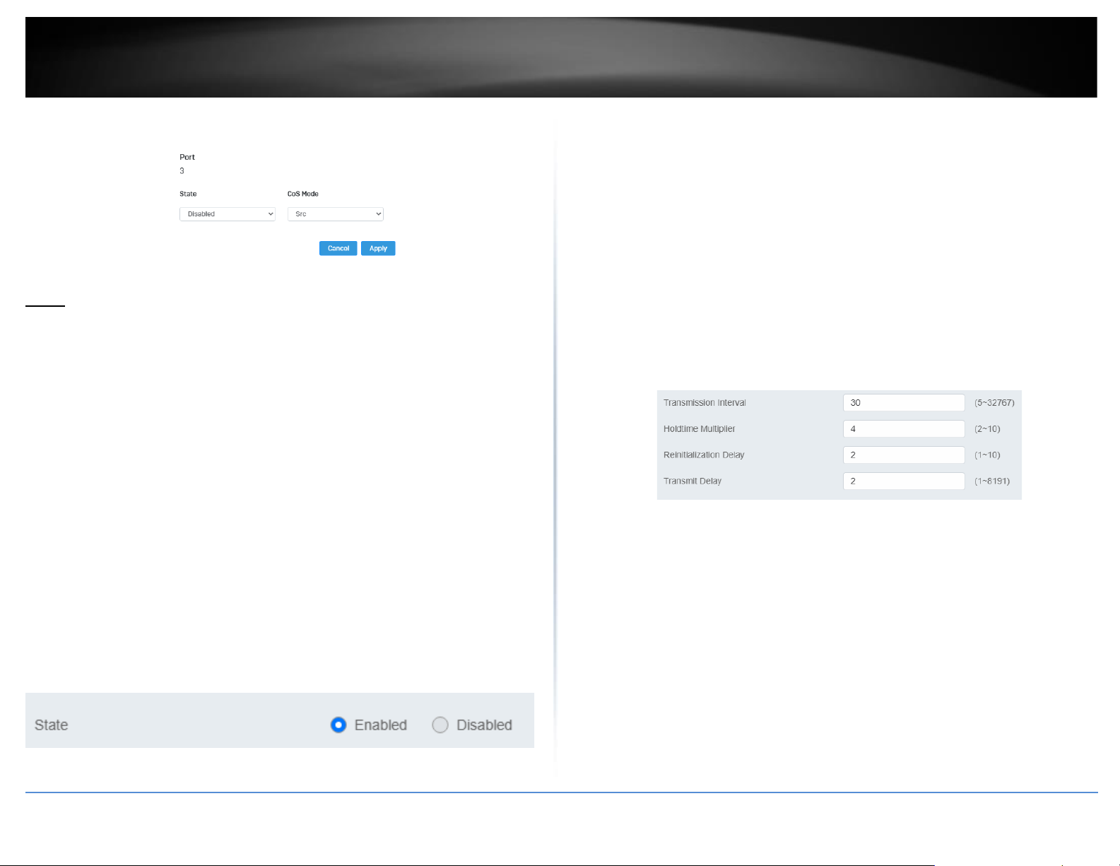
© Copyright 2022 TRENDnet. All Rights Reserved.
45
TRENDnet User’s Guide
Multi-Gig Web Smart Switch Series
LLDP
Enable and configure LLDP
Link Layer Discovery Protocol (LLDP) allows Ethernet network devices, such as switches
and routers, to receive and transmit device-related information to directly connected
devices on the network and to store data that is learned about other devices.
Settings
Network > LLDP > Global Settings
1. Log into your switch management page (see “Access your switch management page”
on page 5).
2. Click on Network, click on LLDP, and click on Settings.
3. Review the settings.
Enabling or Disabling LLDP
• From the LLDP parameter, select one of the following radio button choices and
click Apply to save the settings.
• Enable: The LLDP feature is active.
• Disable: The LLDP feature is inactive.
Configure the LLDP Parameter Settings
Transmission Interval: Sets the transmit interval, which is the interval between regular
transmissions of LLDP advertisements. The range is from 5 to 32767 seconds.
Holdtime Multiplier: Sets the hold multiplier value. The hold time multiplier is
multiplied by the transmit interval to give the Time To Live (TTL) that the switch
advertises to the neighbors. The range is from 2 to 10.
Reinitialization Delay: Sets the reinitialization delay, which is the number of seconds
that must elapse after LLDP is disabled on a port before it can be reinitialized. The range
is from 1 to 10 seconds.
Transmit Delay: Sets the value of the transmission delay timer, which is the minimum
time interval between transmissions of LLDP advertisements due to a change in LLDP
local information. The range is from 1 to 8191 seconds.
Click Apply to save the settings.
View LLDP System Information
Network > LLDP > Local Device
• Chassis ID Subtype: This parameter describes the Chassis ID subtype which is
“macAddress”. You cannot change this parameter.
• Chassis ID: This parameter lists the MAC Address of the switch. You cannot
change this parameter.
• System Name: This parameter lists the System Name of the switch. You can
assign the system name from System Settings.
• System Description: This parameter lists the product name of the switch. You
cannot change this parameter
Page 60
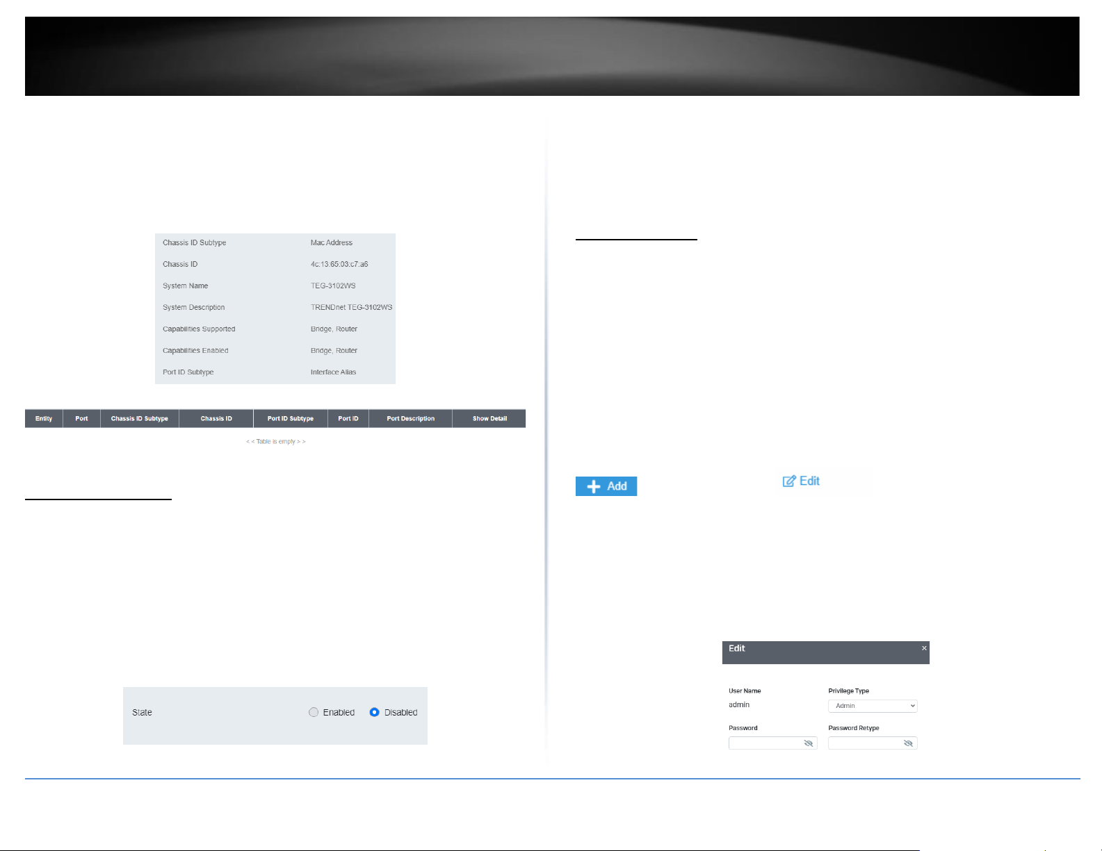
© Copyright 2022 TRENDnet. All Rights Reserved.
46
TRENDnet User’s Guide
Multi-Gig Web Smart Switch Series
• Capabilities Supported: This parameter lists the capabailities that can be
supported. You cannot change this parameter.
• Capabilities Enabled: This parameter lists the capabilities that are enabled. You
cannot change this parameter.
• Port ID Subtype: This parameter lists the Port ID. This parameter cannot be
changed.
Multicast Filtering
Enable Multicast Filtering
Network > Multicast Filtering
1. Log into your switch management page (see “Access your switch management page”
on page 5).
2. Click on Network and click on Multicast Filtering.
3. Select Enabled to enable this feature or Disabled to disable Multicast Filtering
4. At the top right panel, click the Apply button to save the changes to the Flash.
Note: This step saves all configuration changes to the NV-RAM to ensure that if the
switch is rebooted or power cycled, the configuration changes will still be applied
Administration
Changing login credentials
Network > Administration
1. Log into your switch management page (see “Access your switch management page”
on page 5).
2. Click on Network and click on Administration.
3. Click on Add on the top right corner to create a new username and password. To
modify an existing username, click Edit to modify the selected login credentials
4. Review the settings below and click apply to save the changes to your flash
•
Privilege Type: Set the privilege for the selected username to either Admin or
User.
•
Password: Set the password for this new username
•
Password Retype: Re-type your password.
Page 61
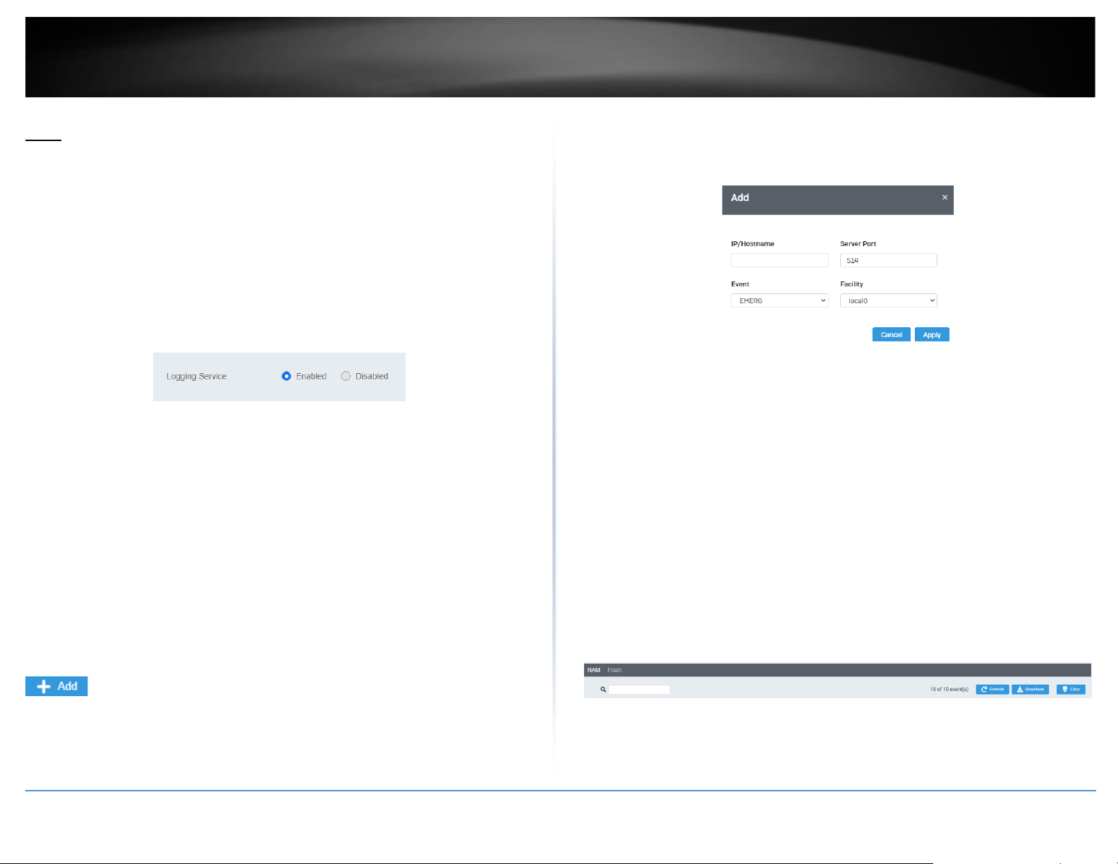
© Copyright 2022 TRENDnet. All Rights Reserved.
47
TRENDnet User’s Guide
Multi-Gig Web Smart Switch Series
Logs
Settings
Network > Logs > Global Settings
1. Log into your switch management page (see “Access your switch management page”
on page 5).
2. Click on Network, click on Logs, and click on Global Settings .
3. Select Enabled to enable logs, or Disabled to disable this feature.
Remote Logging
Network > Logs > Remote Logging
1. Log into your switch management page (see “Access your switch management page”
on page 5).
2. Click on Network, click on Logs, and click on Remote Logging .
3. Click on Add on the top right corner to create a new username and password. To
modify an existing username, click Edit to modify the selected login credentials
4. Review the settings and click Apply to save the changes to the Flash.
•
IP/Hostname: Enter the IP address of the location you want the Log files to go
to.
•
Server Port: Enter the port number of the IP address
•
Event: Select what type of log events will be sent to the IP Address
Log Table
Network > Logs > Log Table
1. Log into your switch management page (see “Access your switch management page”
on page 5).
2. Click on Network, click on Logs, and click on Log Table.
3. Review the settings below.
•
RAM: Displays only log files that are stored on the RAM
•
Flash: Displays only log files that were stored on the Flash
•
Refresh: Refreshes the page
•
Download: Download the log file. Download files can only be saved as .txt files.
•
Clear: Erases all log files
QoS (Quality of Service)
When a port on an Ethernet switch becomes oversubscribed, its egress
Page 62
© Copyright 2022 TRENDnet. All Rights Reserved.
48
TRENDnet User’s Guide
Multi-Gig Web Smart Switch Series
queues contain more packets than the port can handle in a timely manner. In this
situation, the port may be forced to delay the transmission of some packets, resulting in
the delay of packets reaching their destinations. A port may be forced to delay
transmission of packets while it handles other traffic, and, in some situations, some
packets destined to be forwarded to an oversubscribed port from other switch ports
may be discarded.
Minor delays are often of no consequence to a network or its performance. But there
are applications, referred to as delay or time sensitive applications, which can be
impacted by packet delays. Voice transmission and video conferences are two examples.
If packets carrying data in either of these cases are delayed from reaching their
destination, the audio or video quality may suffer.
This is where Cost of Service (CoS) is of value. It allows you to manage the flow of traffic
through a switch by having the switch ports give higher priority to some packets, such as
delay sensitive traffic, over other packets. This is referred to as prioritizing traffic.
Global Settings
Set QoS settings
1. Log into your switch management page (see “Access your switch management page”
on page 5).
2. Click on QoS and click on Global Settings.
3. Select Enabled to enable QoS and Disabled to disable this feature.
4. Set the scheduling method:
• Strict Priority - The port transmits all packets out of higher
priority queues before transmitting any from the lower priority
queues.
• WRR (Weighted RoundRobin) - The port transmits a set number
of packets from each queue, in a round robin fashion, so that each
has a chance to transmit traffic.
4. Select the Trust Mode:
•
DSCP – Priority of packets is based on the ToS (Types of Service) field in the IP
header
•
802.1p – Priority of packets is based off of the PRI value.
•
802.1p – DSCP -
CoS
Set CoS priority settings
QoS > CoS Mapping
Note: Before mapping the CoS priorities and the egress queues, you must disable the
Jumbo frame parameter on each port. When Jumbo frames are enabled, COS cannot be
enabled.
1. Log into your switch management page (see “Access your switch management page”
on page 5).
2. Click on QoS and click on CoS Mapping.
3. In QoS Status, select the CoS Table (0-7) that applies to your configuration and click
Edit.
4. Set each Queue ID (1-8) for the selected CoS Table. Click Apply to save the settings.
Page 63
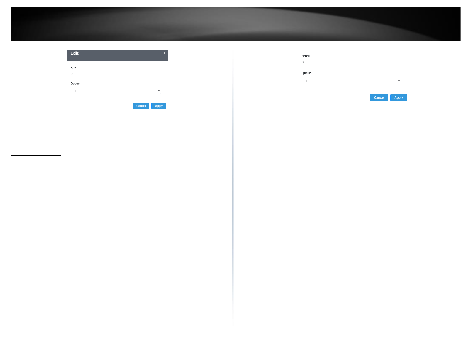
© Copyright 2022 TRENDnet. All Rights Reserved.
49
TRENDnet User’s Guide
Multi-Gig Web Smart Switch Series
Note: This step saves all configuration changes to the NV-RAM to ensure that if the
switch is rebooted or power cycled, the configuration changes will still be applied.
DSCP Mapping
Set DSCP (Differentiated Services Code Point) Class Mapping settings
QoS > DSCP Mapping
If you choose to use the DSCP tags in your Access Control policy configuration, each
DSCP value (0-63) that is relevant to your configuration needs to be mapped to one of
the four egress queues (Low, Medium, High, or Highest). The default queue for all DSCP
values is 0. To assign the queue mappings to the DSCP values, perform the following
procedure.
1. Log into your switch management page (see “Access your switch management page”
on page 5).
2. Click on QoS and click on DSCP Mapping.
3. Select the relevant DSCP value to configure and click Edit to modify the Queue ID for
the selected DSCP value. Click Apply to save the settings.
Note: This step saves all configuration changes to the NV-RAM to ensure that if the
switch is rebooted or power cycled, the configuration changes will still be applied.
Page 64
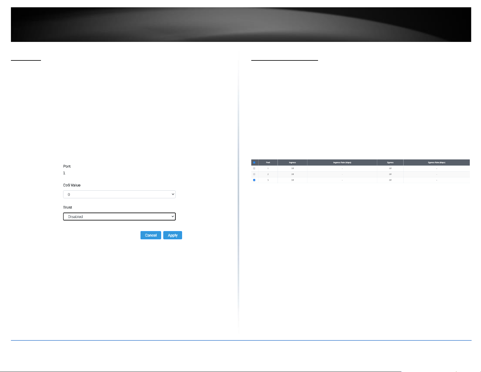
© Copyright 2022 TRENDnet. All Rights Reserved.
50
TRENDnet User’s Guide
Multi-Gig Web Smart Switch Series
Port CoS
Set Port Priority
QoS > Port CoS
The Port Priority values are assigned to an untagged frame at ingress for internal
processing in the switch. This procedure explains how to change the default mappings of
port priorities to the User Priority. This is set at the switch level. You cannot set this at
the per-port level. To change the port priority mappings, perform the following
procedure.
1. Log into your switch management page (see “Access your switch management page”
on page 5).
2. Click on QoS and click on Port CoS.
3. For each port whose priority you want to change, select a priority (0-7, Ignore) in the
CoS Value. Click Apply to save the settings.
4. At the bottom of the left hand panel, click Apply.
.
Bandwidth Control
Bandwidth Control
QoS > Bandwidth Control
This section allows you to configure the DLF (Destination Lookup Failure), broadcast,
and multicast storm settings for each switch port.
1. Log into your switch management page (see “Access your switch management page”
on page 5).
2. Click on QoS, click on Bandwidth Control
3. Select the port to modify and click the Edit button.
4. Review the settings below and click Apply to save your settings.
•
Ingress – Select Enabled to enable Ingress Rate Limiting or Disabled to disable
this feature.
•
Ingress Rate (kbps) - Enter the ingress rate limit value.
•
Egress – Select Enabled to enable Egress Rate Limiting or Disabled to disable
this feature.
•
Egress Rate (kbps) – Enter the egress rate limit value.
Page 65
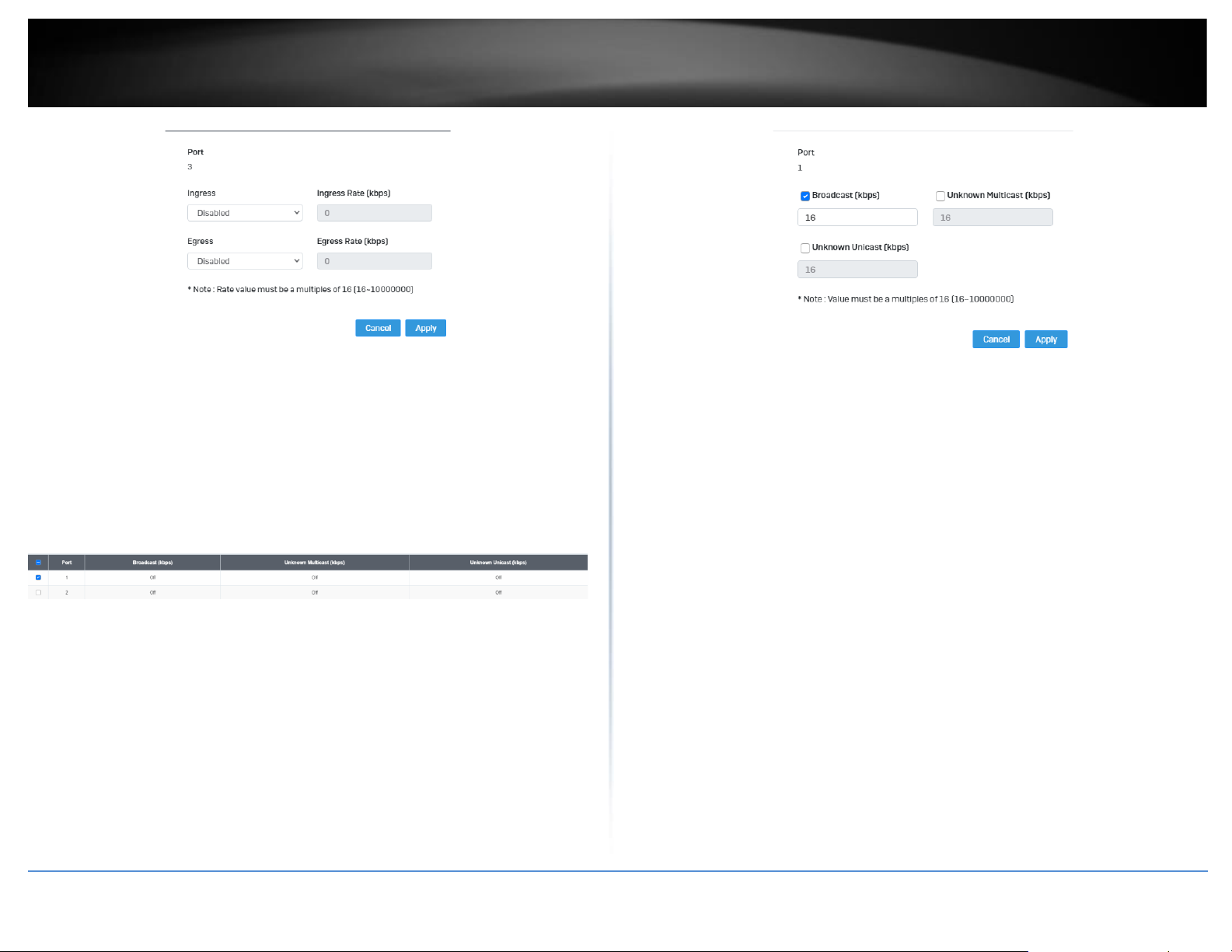
© Copyright 2022 TRENDnet. All Rights Reserved.
51
TRENDnet User’s Guide
Multi-Gig Web Smart Switch Series
Storm Control
QoS > Storm Control
1. Log into your switch management page (see “Access your switch management page”
on page 5).
2. Click on QoS, click on Storm Control
3. Select the port to and click Edit to modify.
4. Review the settings for each port. Click Apply to save the settings.
• Broadcast – Click the empty box to enable Broadcast and enter
the limit value for broadcast in kbps.
• Unknown Multicast – Click the empty box to enable Multicast and
enter the limit value for broadcast in kbps.
• Unknown Unicast – Click the empty box to enable Unicast and
enter the limit value for broadcast in kbps.
Note: Modifying settings in the row marked All, will apply the settings to all
ports.
Page 66
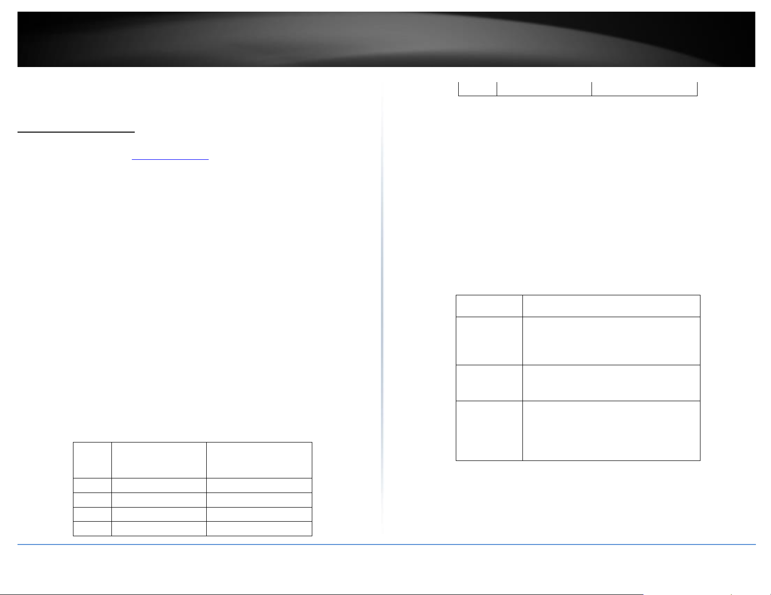
© Copyright 2022 TRENDnet. All Rights Reserved.
52
TRENDnet User’s Guide
Multi-Gig Web Smart Switch Series
PoE (Power over Ethernet)
Power over Ethernet
Note: This PoE section only applies to models with PoE. For a list of multi-gig PoE Web
Smart switches, please go to www.trendnet.com
The main advantage of PoE is that it can make installing a network easier. The selection
of a location for a network device is often limited by whether there is a power source
nearby. This constraint limits equipment placement or requires the added time and cost
of having additional electrical sources installed. However, with PoE, you can install PoE
compatible devices wherever they are needed without having to worry about whether
there is power source nearby.
Power Sourcing Equipment (PSE)
A device that provides PoE to other network devices is referred to as power sourcing
equipment (PSE). The Gigabit Web Smart PoE+ Switch is a PSE device which provides DC
power to the network cable and functions as a central power source for other network
devices.
Powered Device (PD)
A device that receives power from a PSE device is called a powered device (PD).
Examples include wireless access points, IP phones, webcams, and even other Ethernet
switches.
PD Classes PDs are grouped into five classes. The classes are based on the amount of
power that PDs require. The Gigabit Web Smart PoE+ Switch supports all five classes.
Class
Maximum Power
Output
from a Switch Port
Power Ranges of the PDs
0
15.4W
0.44W to 12.95W
1
4.0W
0.44W to 3.84W
2
7.0W
3.84W to 6.49W
3
15.4W
6.49W to 12.95W
4
34.2W
12.85W to 25.5W
Power Budget
Power budget is the maximum amount of power that the PoE switch can provide at one
time to the connected PDs. Port Prioritization As long as the total power requirements
of the PDs is less than the total available power of the switch, it can supply power to all
of the PDs.
However, when the PD power requirements exceed the total available power, the
switch denies power to some ports based on a process called port prioritization.
The ports on the PoE switch are assigned to one of three priority levels. These levels and
descriptions are listed in Table 3. Without enough power to support all the ports set to
the same priority level at one time, the switch provides power to the ports based on the
port number, in ascending order. For example, when all of the ports in the switch are set
to the low priority level and the power requirements are exceeded on the switch, port 1
has the highest priority level, port 2 has the next highest priority level and so forth.
Priority Level
Description
Critical
This is the highest priority level. Ports set to
the Critical level are guaranteed to receive
power before any of the ports assigned to
the other priority levels.
High
Ports set to the High level receive power
only when all the ports assigned to the
Critical level are already receiving power.
Low
This is the lowest priority level. Ports set to
the Low level receive power only when all
the ports assigned to the Critical and High
levels are already receiving power. This
level is the default setting.
Page 67
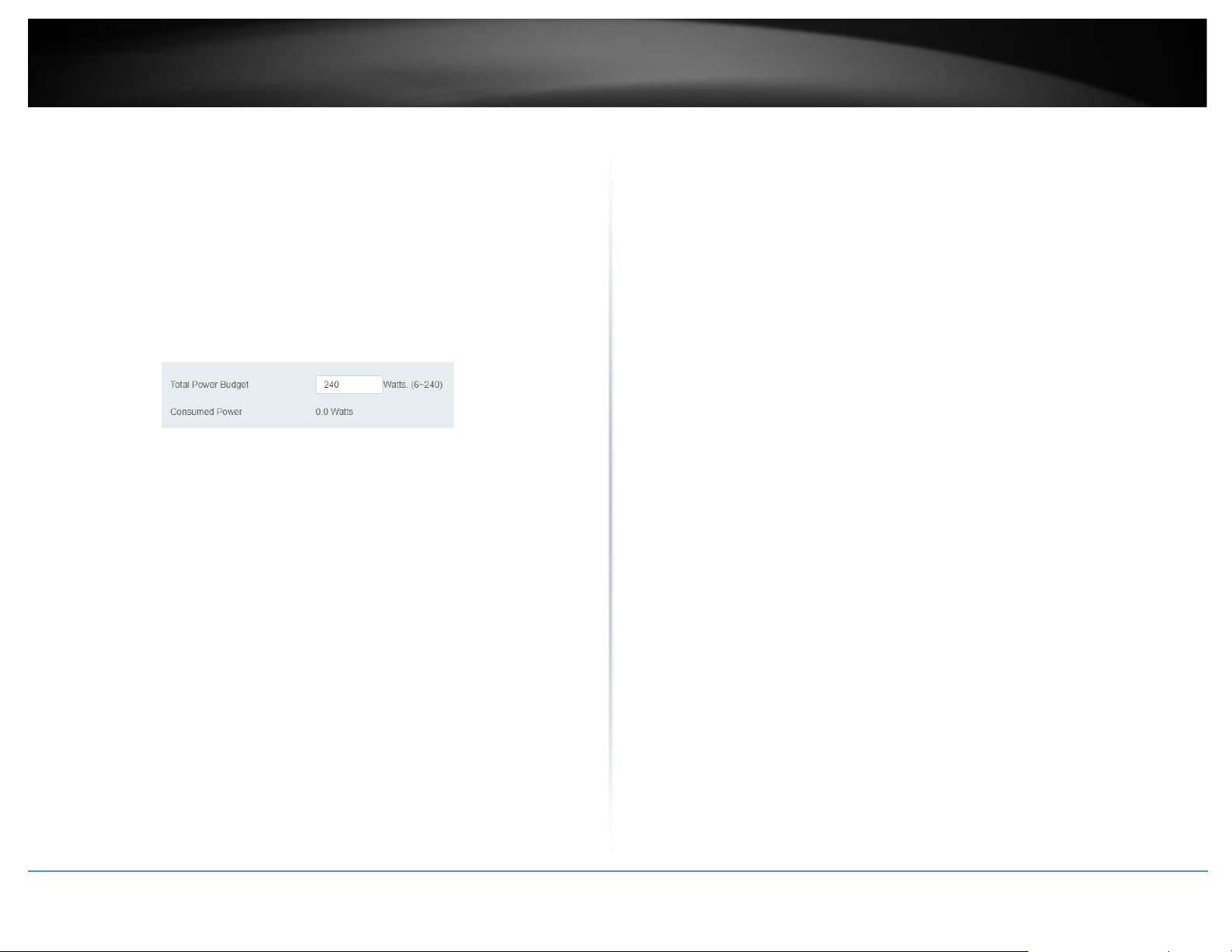
© Copyright 2022 TRENDnet. All Rights Reserved.
53
TRENDnet User’s Guide
Multi-Gig Web Smart Switch Series
Configure PoE Budget
PoE > Power Budget
1. Log into your switch management page (see “Access your switch management page”
on page 5).
2. Click on PoE and click on Power Budget.
3. Enter the max PoE budget of the switch. The total consumed wattage is also shown.
Note: By default, the PoE budget is set to 240W (maximum budget).
4. Click Apply to save your settings to the flash.
Configure PoE Port Settings
PoE > PoE Port Settings
1. Log into your switch management page (see “Access your switch management page”
on page 5).
2. Click on PoE and click on PoE Port Settings.
3. Review the settings for each port.
• State - The PoE port status is given as follows:
• ON - The port is supplying PoE power.
• OFF - The port is not supplying PoE power.
• Priority - Indicates the port priority: Low, High, or Critical.
• Power Limit Type – Indicates the power limit by class or power limit defined by
the user.
• User Power Limit(W) -
• Status – Displays the current status
• TimeRange – Select a defined PoE TimeRange. N/A will be displayed if no time
ranges have been created.
• Class - The PoE class is indicated the class of the PD. N/A is displayed when the
port is not supplying power
• Output Voltage(V) - Indicates the Voltage in volts as measured at the port
when the port is supplying power to the PD.
• Output Current(mA) - Indicates the Current in milliamps that the port is
supplying to the PD.
• Output Power(mW) - Indicates the Power in milliwatts that the port is
supplying power to the PD.
4. To modify the settings, select the port and click Edit. Review the settings below and
click Apply to save your settings to the flash.
4 State – Select Enabled to enable PoE on this port or Disabled to
disable PoE from the selected port.
5 Priority – Set the priority of this port.
6 Power Limit Type – Select Auto Class for the switch to determine
the amount of power need to power your PD or User defined to
manually define the amount of power your PD device needs.
7 Schedule Name – Select the schedule rule to follow.
Note: In order to set the schedule, the “Time Range” must first be
configured.
Page 68
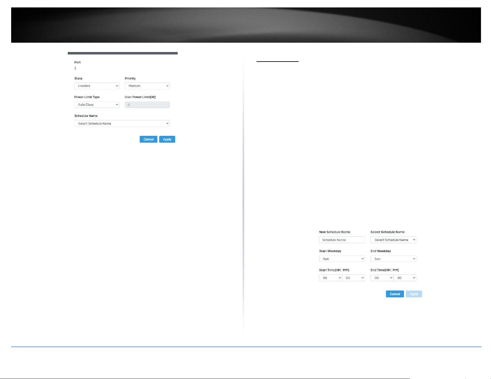
© Copyright 2022 TRENDnet. All Rights Reserved.
54
TRENDnet User’s Guide
Multi-Gig Web Smart Switch Series
4. Click Apply to save your settings to the flash.
Note: This step saves all configuration changes to the NV-RAM to ensure that if the
switch is rebooted or power cycled, the configuration changes will still be applied.
Flick Reboot
PoE > Flick Reboot
Flick Reboot allows the switch to continuously send power to PoE devices connected on
the switch while the switch reboots. This prevents any PD device connected to the
switch reboot while the switch is rebooting itself.
1. Log into your switch management page (see “Access your switch management page”
on page 5).
2. Click on PoE and click on Flick Reboot.
3. Select Enabled to enable continuous PoE to your PD device while the switch reboots,
or select Disabled to disable this feature.
Note: By default, Flick Reboot is set to Disabled.
Time Range
Configure PoE Time Range
PoE > Time Range
1. Log into your switch management page (see “Access your switch management page”
on page 5).
2. Click on PoE and click on Time Range.
3. Click Add to create a new PoE schedule. Review the settings for each port. Next to
each port entry, click Apply to save the settings.
• New Schedule Name – Enter a description for the PoE schedule.
• Select Schedule Name – Select a previous created schedule to edit.
• Start Weekday - Set the start day of the PoE time range.
• End Weekday - Set the end day of the PoE time range.
• Start Time – Set the start time of the PoE time range.
• End Time - Set the end day of the PoE time range.
4. Click Apply to save the settings to the Flash.
Note: This step saves all configuration changes to the NV-RAM to ensure that if the
switch is rebooted or power cycled, the configuration changes will still be applied
Page 69
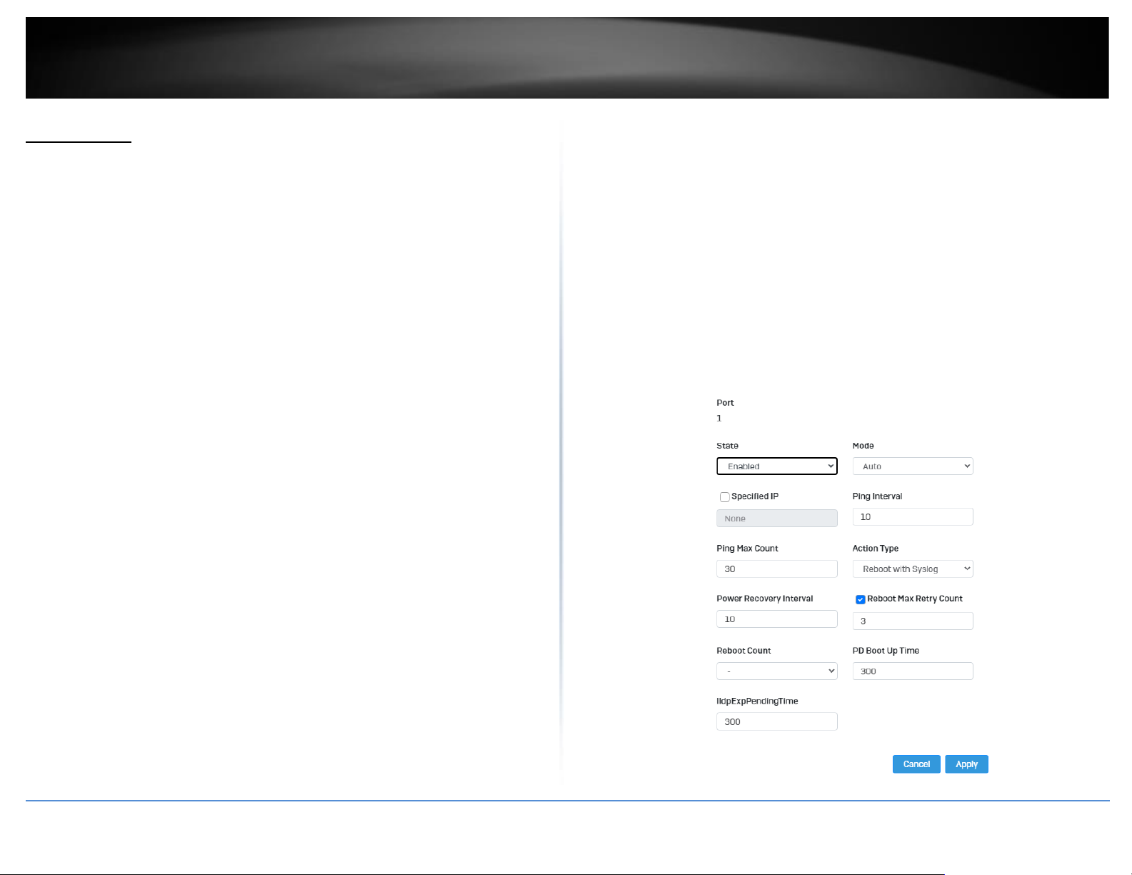
© Copyright 2022 TRENDnet. All Rights Reserved.
55
TRENDnet User’s Guide
Multi-Gig Web Smart Switch Series
PD Lifeguard
Configure PD Alive Check
PoE > PD Lifeguard > Global Settings
PD Lifeguard is used to check the connection between the switch and the device
connected to it. The switch sends a ping, and if the device does not respond, the switch
will try to revive the device by doing a power cycle of the connected device.
1. Log into your switch management page (see “Access your switch management page”
on page 5).
2. Click on PoE, click on PD Lifeguard, and click on Global Settings.
3. Select Enabled to enable PD Lifeguard and Disabled to disable this feature.
Advanced Configuration
PoE > PD Lifeguard > Advanced Configuration
1. Log into your switch management page (see “Access your switch management page”
on page 5).
2. Click on PoE, click on PD Lifeguard, and click on Advanced Configuration.
3. Review the settings for each port. Next to each port entry, click Apply to save the
settings.
1 State: Select Enabled to enable PD Alive check and Disabled to
disable it
2 Mode: Select Auto or Force Ping.
3 Specified IP: Enter the IP address of the device that is connected to
the port
4 Ping Interval: Enter the desired time for how often the switch will
send a ping to the connected device
5 Ping Max Count: Enter the max number of times the switch will ping
the PD device before the switch power cycles the PD device.
6 Action Type: Select if the switch should Reboot the PD device or save
it to the syslog.
7 Power Recovery Interval: Enter the time it takes for your PD device
to boot up. If the entered time is too short, the switch will keep
powering on and off the device.
8 Reboot Max Retry Count: Max number of reboot retries before the
switch stops
Page 70
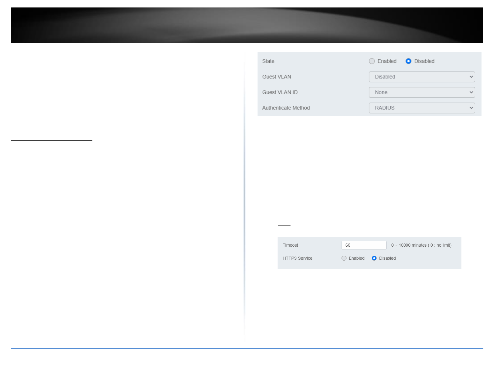
© Copyright 2022 TRENDnet. All Rights Reserved.
56
TRENDnet User’s Guide
Multi-Gig Web Smart Switch Series
4. At the bottom of the left hand panel, click Apply to save the settings to the flash. .
Note: This step saves all configuration changes to the NV-RAM to ensure that if the
switch is rebooted or power cycled, the configuration changes will still be applied.
Security
802.1X Authentication
Set 802.1X
Security > 802.1X > Global Settings
1. Log into your switch management page (see “Access your switch management page”
on page 5).
2. Click on Security, click on 802.1X, and click on Global Settings.
3. Review the settings for each port. Next to each port entry, click Apply to save the
settings.
• State: Click Enabled to enable 802.1X or Disabled to disable this feature.
• Guest VLAN: Select Enabled to enable 802.1X for Guest VLAN or Disabled to
disable this feature.
• Guest VLAN ID: Select the VLAN ID to apply this setting to.
• Authenticate Method: Select RADIUS, TACAS+ or Local as the authenticate
method.
Timeout
Security > Access > Web
1. Log into your switch management page (see “Access your switch management page”
on page 5).
2. Click on Security, click on Access, and click on Web.
3. Review the settings and click Apply to save the settings.
•
Timeout: Input the length of time before your switch times out. Regardless of
activity/inactivity, the switch will timeout in the specific time.
Note: By default, the timeout duration is set to 30 minutes.
•
HTTPS Service: Select Enabled to enable this feature or Disabled to disable it.
CLI Timeout
Security > Access > Web
1. Log into your switch management page (see “Access your switch management page”
on page 5).
Page 71
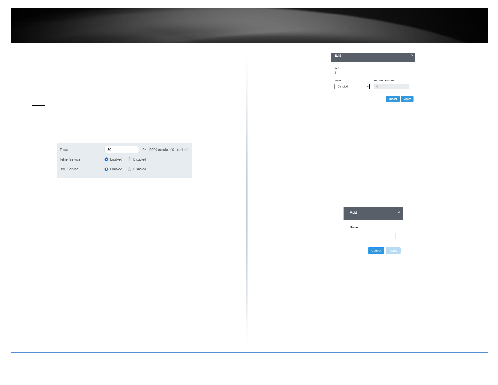
© Copyright 2022 TRENDnet. All Rights Reserved.
57
TRENDnet User’s Guide
Multi-Gig Web Smart Switch Series
2. Click on Security, click on Access, and click on CLI.
3. Review the settings and click Apply to save the settings.
•
Timeout: Input the length of time before your switch times out. Regardless of
activity/inactivity, the switch will timeout in the specific time.
Note: By default, the timeout duration is set to 30 minutes.
•
Telnet Service: Select Enabled to enable Telnet or Disabled to disable this
feature.
•
SSH Service: Select Enabled to enable Telnet or Disabled to disable this feature.
Port Security
Security > Port Security
1. Log into your switch management page (see “Access your switch management page”
on page 5).
2. Click on Security, and click on Port Security.
3. Select the port to configure, and click Edit to configure the selected port.
4. Review the settings and click Apply to save your settings.
•
State: Select Enabled from the drop down menu to enable this feature and
Disabled to disable this feature.
•
Max MAC Address: Enter the max number of MAC Addresses. The max
number is 256.
Access Control: Creating MAC ACL
Security > Access Control > MAC ACL
1. Log into your switch management page (see “Access your switch management page”
on page 5).
2. Click on Security, then click on Access Control, and click on MAC ACL.
3. Click the Add button to create a new ACL.
4. Input a name in the field and click Apply to save your new ACL name to the Flash.
Access Control: Configuring MAC ACL
Security > Access Control > MAC ACE
1. Log into your switch management page (see “Access your switch management page”
on page 5).
Page 72
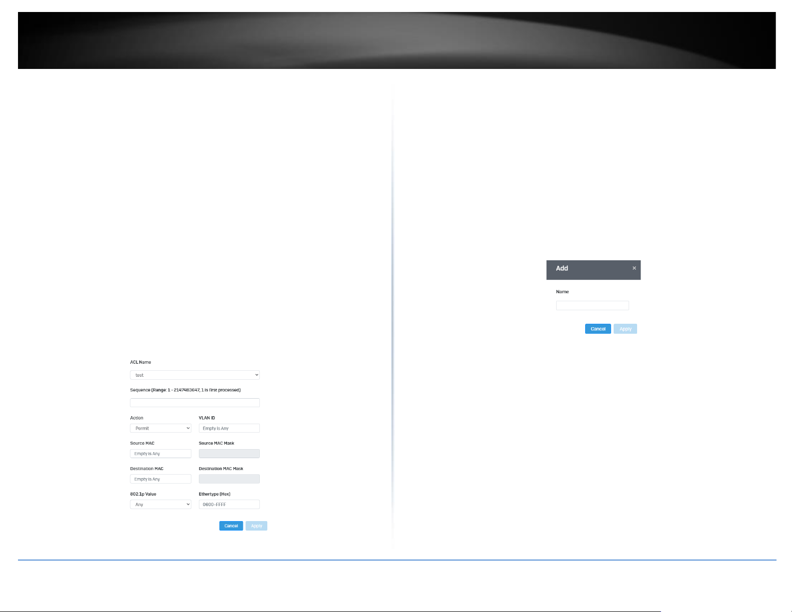
© Copyright 2022 TRENDnet. All Rights Reserved.
58
TRENDnet User’s Guide
Multi-Gig Web Smart Switch Series
2. Click on Security, then click on Access Control, and click on MAC ACE.
3. Review the settings below and click Apply to save your settings.
•
ACL Name: Select the ACL name you would like to configure.
•
Sequence:
•
Action: Defines the ACl action linked to the rule criteria.
• Permit- This selection allows ingress packets that conform to the
specified ACL criteria.
• Deny- This selection drops ingress packets that conform to the
specified ACL criteria.
1. VLAN ID: Enter the VLAN ID to associate with this MAC ACL.
•
Source MAC: Input the source of the MAC address
•
Destination MAC: Input the destination MAC address
•
Source MAC Mask & Destination MAC Mask: Enter the mask of the Source
MAC and Destination MAC.
•
802.1p Value: Select the priority to assign with 7 being the highest priority and
0 being the lowest.
•
Ethertype (Hex)- Specifies EtherType packet filtering
Access Control: Creating IPv4 ACL
Security > Access Control > IPv4 ACL
1. Log into your switch management page (see “Access your switch management page”
on page 5).
2. Click on Security, then click on Access Control, and click on IPv4 ACL.
3. Click the Add button to create a new ACL.
4. Input a name in the field and click Apply to save your new ACL name to the Flash.
Access Control: Configuring IPv4 ACL
Security > Access Control > IPv4 ACE
1. Log into your switch management page (see “Access your switch management page”
on page 5).
2. Click on Security, then click on Access Control, and click on MAC ACE.
3. Review the settings below and click Apply to save your settings.
•
ACL Name: Select the ACL name you would like to configure.
Page 73
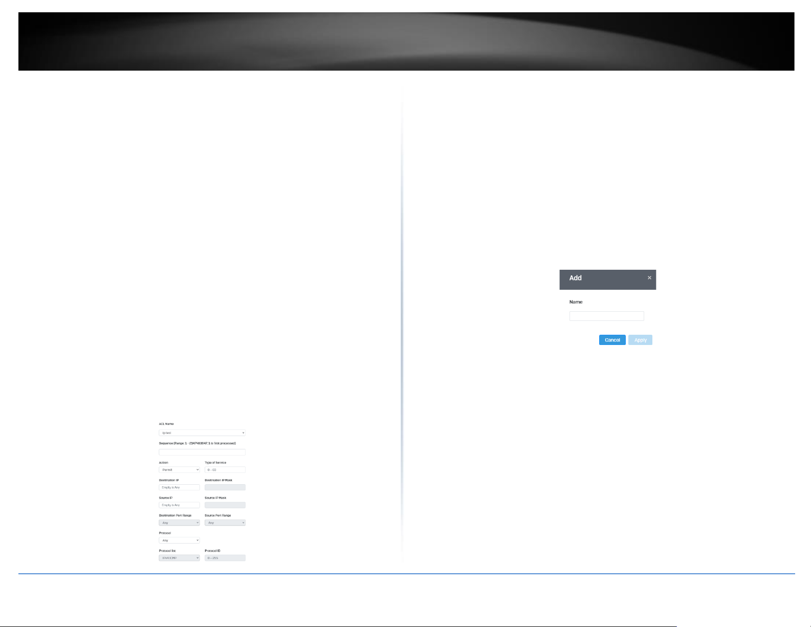
© Copyright 2022 TRENDnet. All Rights Reserved.
59
TRENDnet User’s Guide
Multi-Gig Web Smart Switch Series
•
Sequence:
•
Action: Defines the ACl action linked to the rule criteria.
• Permit- This selection allows ingress packets that conform to the
specified ACL criteria.
• Deny- This selection drops ingress packets that conform to the
specified ACL criteria.
2. Type of Service: Enter a number in the Type of Service field within the
range of 0 to 63. This field indicates the DSCP level of interest. This field is
not mandatory and you may elect to leave it blank.
•
Destination IP: Input the destination IP address
•
Source IP: Input the source of the IP address
•
Source IP Mask & Destination IP Mask: Enter the mask of the Source MAC and
Destination MAC.
•
Protocol: Select the protocol
• Select from list: Select from a pre-defined list below under “IGMP List”
• Select from Protocol ID: Input the protocol ID between the range of 0-
255.
•
IGMP: Select the from the drop down menu
• Select from list: Select from a pre-defined list below under “Protocol
List”
• Select from IGMP ID: Input the protocol ID between the range of 0-
255.
Access Control: Creating IPv6 ACL
Security > Access Control > IPv6 ACL
1. Log into your switch management page (see “Access your switch management page”
on page 5).
2. Click on Security, then click on Access Control, and click on IPv6 ACL.
3. Click the Add button to create a new ACL.
4. Input a name in the field and click Apply to save your new ACL name to the Flash.
Access Control: Configuring IPv6 ACL
Security > Access Control > IPv4 ACE
1. Log into your switch management page (see “Access your switch management page”
on page 5).
2. Click on Security, then click on Access Control, and click on IPv6 ACE.
3. Review the settings below and click Apply to save your settings.
•
ACL Name: Select the ACL name you would like to configure.
•
Sequence:
•
Action: Defines the ACl action linked to the rule criteria.
Page 74
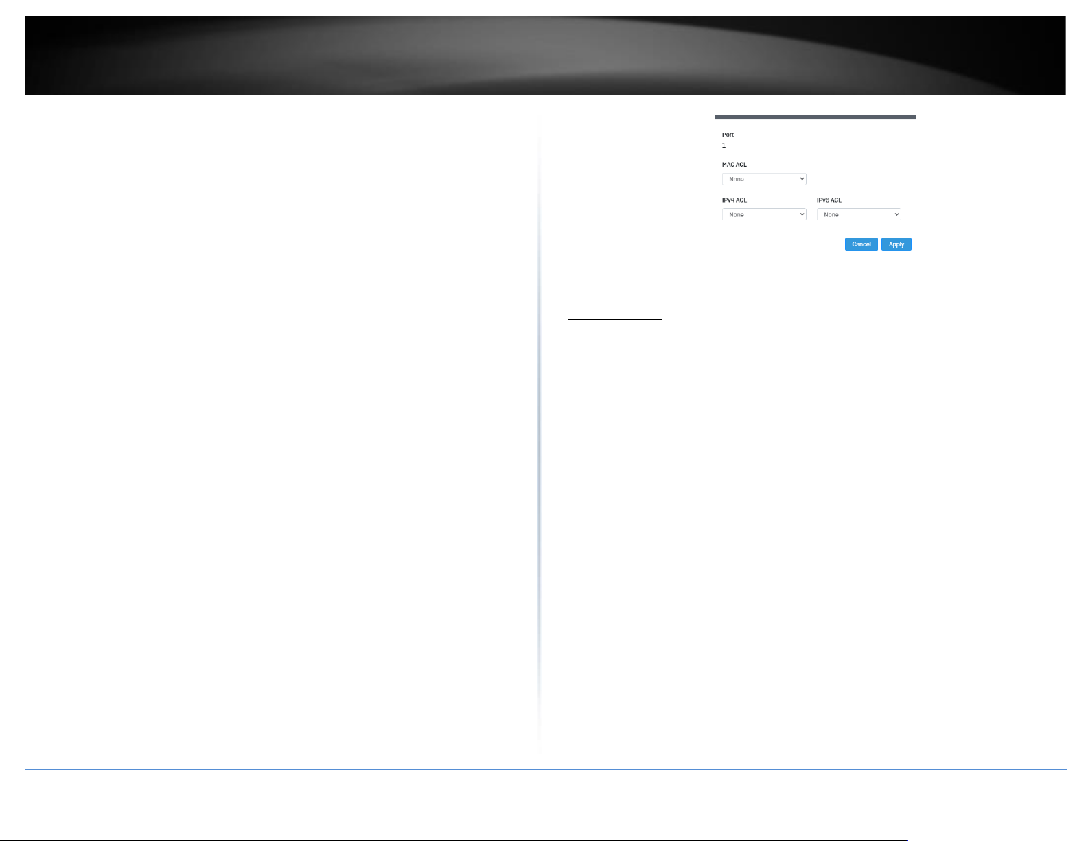
© Copyright 2022 TRENDnet. All Rights Reserved.
60
TRENDnet User’s Guide
Multi-Gig Web Smart Switch Series
• Permit- This selection allows ingress packets that conform to the
specified ACL criteria.
• Deny- This selection drops ingress packets that conform to the
specified ACL criteria.
3. Type of Service: Enter a number in the Type of Service field within the
range of 0 to 63. This field indicates the DSCP level of interest. This field is
not mandatory and you may elect to leave it blank.
•
Destination IP: Input the destination IP address
•
Source IP: Input the source of the IP address
•
Source IP Mask & Destination IP Mask: Enter the mask of the Source MAC and
Destination MAC.
•
Protocol: Select the protocol
• Select from list: Select from a pre-defined list below under “IGMP List”
• Select from Protocol ID: Input the protocol ID between the range of 0-
255.
•
IGMP: Select the from the drop down menu
• Select from list: Select from a pre-defined list below under “Protocol
List”
• Select from IGMP ID: Input the protocol ID between the range of 0-
255.
Port Binding
Security > Access Control > Port Binding
1. Log into your switch management page (see “Access your switch management page”
on page 5).
2. Click on Security, click on Access Control, and click on Port Binding.
3. Select the port you would like to bind to a specific ACL and click Edit.
4. Select from the list of ACLs and click Apply to save your settings.
Dial-in User
Create Dial-In Users (Local Authentication Method)
Security > Dial-in User
Dial-in User feature provides the local authentication server for port security when a
remote (RADIUS) server is not available.
The Dial-in User (local) authentication method allows you to set up 802.1x
authentication parameters internally in the Switch. In this case, the user name and
password combinations are entered with an optional VLAN when they are defined.
Based on these entries, the authentication process of a supplicant is done locally by the
Switch Management Utility using a standard EAPOL (EAP over LAN) transaction.
1. Log into your switch management page (see “Access your switch management page”
on page 5).
2. Click on Security and click on Dial-In User.
3. Click Add to create a dial-in user for local authentication.
4. Review the settings.
To create a dial-in user for local authentication, use the following procedure:
• In the User Name field, type a name for the user.
• In the Permission field, select Allow to allow this user to access or Deny to not
grant this user access.
Page 75
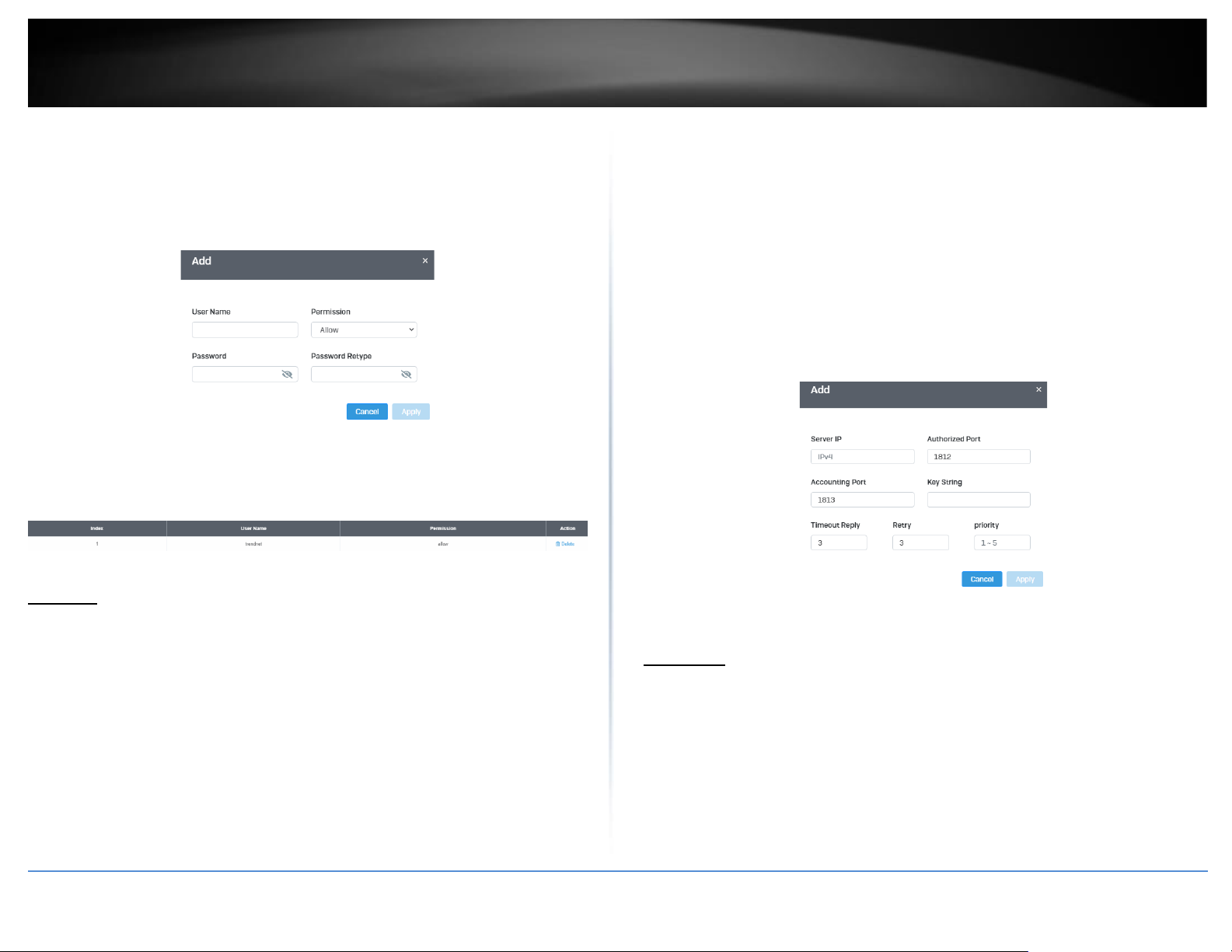
© Copyright 2022 TRENDnet. All Rights Reserved.
61
TRENDnet User’s Guide
Multi-Gig Web Smart Switch Series
• In the Password field, type a password for the user.
• In the Password Retype field, re-type the password to confirm.
Click Apply to add the entry to the table.
In the list, you can Delete the entry.
RADIUS
Add Radius Servers (RADIUS Authentication Method)
Security > RADIUS Server
1. Log into your switch management page (see “Access your switch management page”
on page 5).
2. Click on Security and click on Radius Server.
3. Click Add to create a new Radius Server.
4. Review the settings.
• Server IP–Input the IPv4 IP address of the RADIUS server you would like to add.
• Authorized Port (1 - 65535) –Set the RADIUS authentic server(s) UDP port. The
default port is 1812.
• Accounting Port (1 - 65535) –Set the RADIUS account server(s) UDP port. The
default port is 1813.
• Key String – Enter the default authentication and encryption key for RADIUS
communication between the device and the RADIUS server.
• Timeout Reply – Enter the max number of timeouts before it retries
• Retry – Enter the max number of retries before it stops trying to recover
• Server Priority – Enter the RADIUS Server priority (Highest: 1, Lowest: 5).
Click Apply to add the entry to the table.
TACACS+
Add TACACS+ Servers (TACACS+ Authentication Method)
Security > TACACS+
Terminal Access Controller Access Control System (TACACS+) provides centralized
security user access validation. The system supports up-to 5 TACACS+ servers.
TACACS+ provides a centralized user management system, while still retaining
consistency with RADIUS and other authentication processes.
The TACACS+ protocol ensures network integrity through encrypted protocol exchanges
between the client and TACACS+ server. The user-assigned TACACS+ parameters are
Page 76
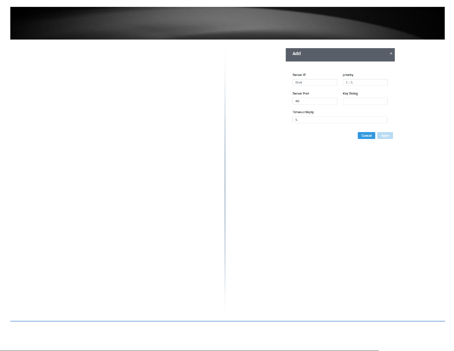
© Copyright 2022 TRENDnet. All Rights Reserved.
62
TRENDnet User’s Guide
Multi-Gig Web Smart Switch Series
applied to newly defined TACACS+ servers. If values are not defined, the system defaults
are applied to the new TACACS+ servers.
1. Log into your switch management page (see “Access your switch management page”
on page 5).
2. Click on Security and click on TACACS+.
3. Click Add to create a new TACAS+
4. Review the settings.
• Server IP– Enter the TACACS+ Server IP address.
• Server Priority – Enter the TACACS+ Server priority (Highest: 1, Lowest: 5).
• Server Port – Enter the port number via which the TACACS+ session occurs. The
default port is port 49.
• Key String – Enter the default authentication and encryption key for TACACS+
communication between the device and the TACACS+ server.
• Timeout – Enter the amount of time (in seconds) the device waits for an
answer from the TACACS+ server before retrying the query, or switching to the
next server. Possible field values are 1-255. The default value is 5.
Click Apply to add the entry to the table.
Page 77
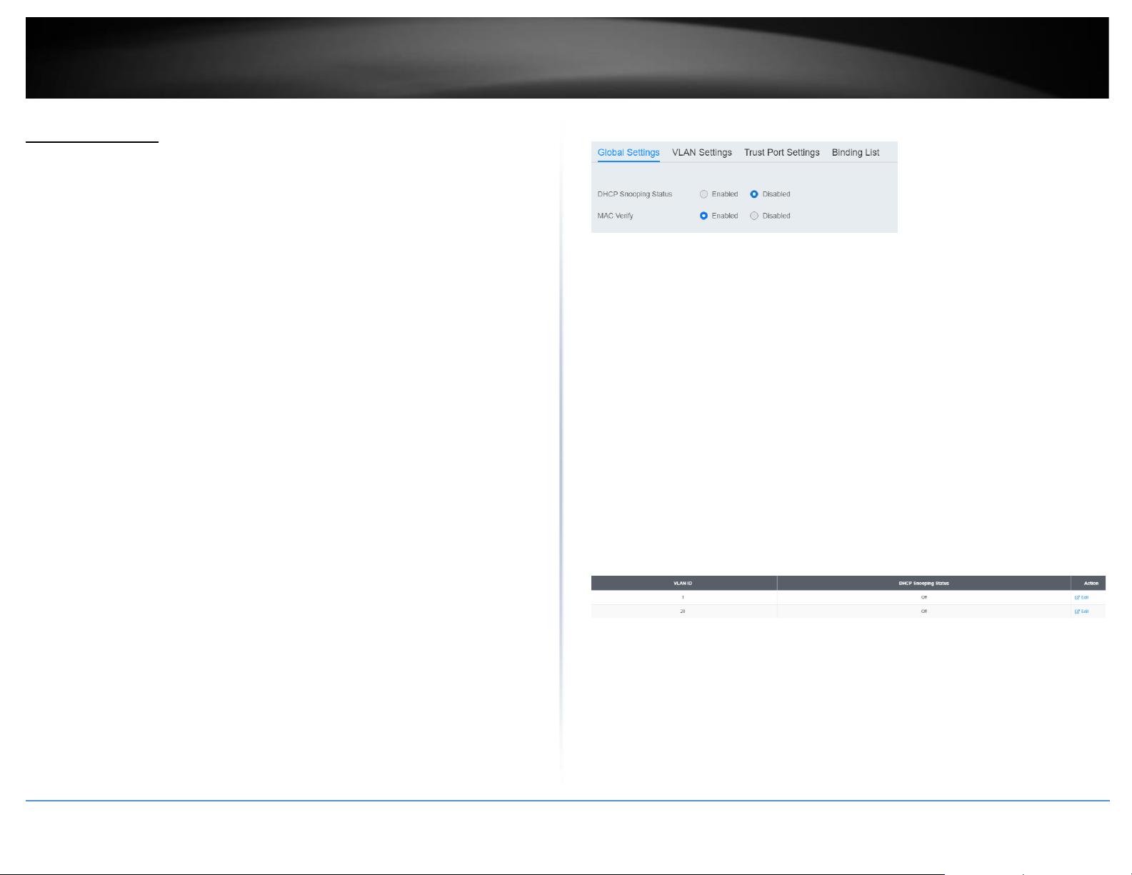
© Copyright 2022 TRENDnet. All Rights Reserved.
63
TRENDnet User’s Guide
Multi-Gig Web Smart Switch Series
DHCP Snooping
Settings
DHCP Snooping > Settings
Here is a summary of the rules to observe when you configure DHCP Snooping:
• A trusted port is connected to one of the following:
o Directly to the legitimate trusted DHCP Server.
o A network device relaying DHCP messages to and from a trusted
server.
o Another trusted source such as a switch with DHCP Snooping enabled.
o Untrusted ports are connected to DHCP clients and to traffic that
originates outside of the local area network.
• The VLANs to which the DHCP Snooping feature applies must be specified in
the DHCP Snooping VLAN Setting configuration.
• Any static IP addresses on the network must be manually added to the Binding
Database.
1. Log into your switch management page (see “Access your switch management page”
on page 5).
2. Click on Security, click on DHCP Snooping, and click on Global Settings.
3. Review the settings..
• DHCP Snooping Status - Select one of the following radio button choices:
o Enabled - This parameter activates the DHCP Snooping feature.
o Disabled - This parameter de-activates the DHCP Snooping
• MAC Verify - Select one of the following choices:
o Enable - The MAC address of each ingress ARP packet is validated
when compared against the Binding Table entries. Invalid ARP packets
are discarded.
o Disable - The MAC address of each ingress ARP packet is not validated
against the Binding Table. All ARP packets are forwarded through the
switch without regard to the IP and MAC Address information in the
packet header.
4. Click Apply to save the settings to the Flash.
Note: This step saves all configuration changes to the NV-RAM to ensure that if the
switch is rebooted or power cycled, the configuration changes will still be applied.
VLAN
Security > DHCP Snooping > VLAN Settings
In this section, you can define an existing VLAN to apply DHCP snooping.
1. Log into your switch management page (see “Access your switch management page”
on page 5).
2. Click on Security, click on DHCP Snooping, and click on VLAN Settings.
3. Select the VLAN ID to edit. You can click Edit to modify an entry.
4. From the drop down menu, select Enabled to enable DHCP Snooping, or Disabled to
disable this feature. .
Page 78
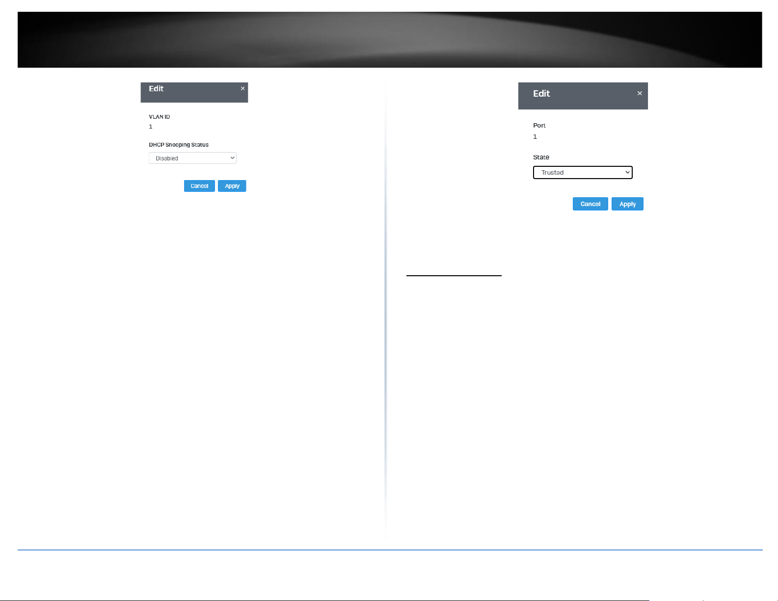
© Copyright 2022 TRENDnet. All Rights Reserved.
64
TRENDnet User’s Guide
Multi-Gig Web Smart Switch Series
4. Click Apply to save the settings to the Flash.
Note: This step saves all configuration changes to the NV-RAM to ensure that if the
switch is rebooted or power cycled, the configuration changes will still be applied.
Trusted Port Interfaces
Security > DHCP Snooping > Trust Port Settings
This section allows you to set trusted port interfaces where DHCP servers can be
connected allows or denies DHCP server information to be received on those ports.
1. Log into your switch management page (see “Access your switch management page”
on page 5).
2. Click on Security, click on DHCP Snooping, and click on Trust Port Settings.
3. Next to each port, click on the bubble to select the port to modify and click Edit.
4. Review the settings:
• Untrusted: This parameter defines the port as untrusted for the DHCP
Snooping feature.
• Trusted: This parameter defines the port as trusted for the DHCP Snooping
feature.
Note: You can select the row labeled ALL to apply settings to all ports.
5. Click Apply to save the settings to the Flash.
Note: This step saves all configuration changes to the NV-RAM to ensure that if the
switch is rebooted or power cycled, the configuration changes will still be applied.
Denial of Service
Denial of Service (DoS)
Security > DoS
The switch has built-in DoS prevention features to restrict specific type of traffic
associated denial of service attacks on your network. By default, all of the DoS settings
are set to Allow, which allow any type of traffic to pass through the switch. Setting one
of the items to Deny will set the switch to check for traffic matching the selected item
and deny any traffic matching the rule. On the other hand, setting one of rules to Deny
may deny a specific type of traffic that may prevent traffic essential to running your
network such as devices in load balancing configuration using virtual IP addresses (Ex. If
ARP MAC SA Mismatch is set to Deny, it may cause devices in load balance configuration
using shared virtual IP addresses communication issues essential for network server
load balancing.) For additional security, you can set these rules to Deny as necessary.
1. Log into your switch management page (see “Access your switch management page”
on page 5).
2. Click on Security and click on DoS
3. Select Enabled to enable DoS or Disabled to disable DoS.
Page 79
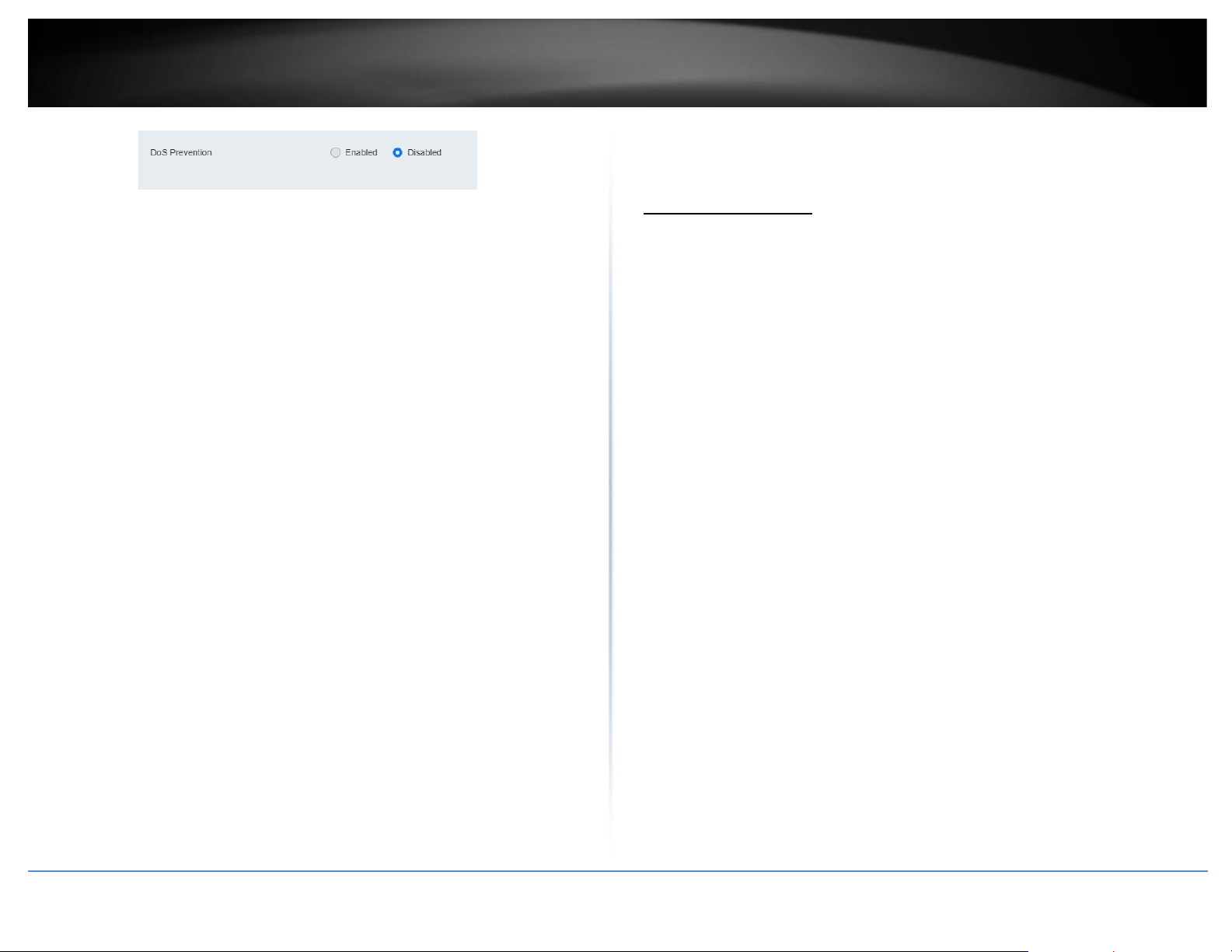
© Copyright 2022 TRENDnet. All Rights Reserved.
65
TRENDnet User’s Guide
Multi-Gig Web Smart Switch Series
4. Click Apply to save the settings to the Flash.
Note: This step saves all configuration changes to the NV-RAM to ensure that if the
switch is rebooted or power cycled, the configuration changes will still be applied.
Tools
Firmware Upgrade
Upgrade your switch’s firmware
Tools > Firmware Upgrade
TRENDnet may periodically release firmware upgrades that may add features or fix
problems associated with your TRENDnet switch model and version. To check if there is
a firmware upgrade available for your device, please check your TRENDnet model and
version using the link. http://www.trendnet.com/downloads/
In addition, it is also important to verify if the latest firmware version is newer than the
one your switch is currently running. To identify the firmware that is currently loaded on
your switch, log in to the switch, click on the System Info section or click on Tools and
click on Firmware Upgrade. The firmware used by the switch is listed as Runtime Image
or Image Version. If there is a newer version available, also review the release notes to
check if there were any new features you may want or if any problems were fixed that
you may have been experiencing.
1. If a firmware upgrade is available, download the firmware to your computer.
2. Unzip the file to a folder on your computer.
Please note the following:
• Do not interrupt the firmware upgrade process. Do not turn off the device or
press the Reset button during the upgrade.
• If you are upgrade the firmware using a laptop computer, ensure that the laptop
is connected to a power source or ensure that the battery is fully charged.
• Disable sleep mode on your computer as this may interrupt the firmware upgrade
process.
• Do not upgrade the firmware using a wireless connection, only using a wired
network connection.
• Any interruptions during the firmware upgrade process may permanently
damage your switch.
Page 80
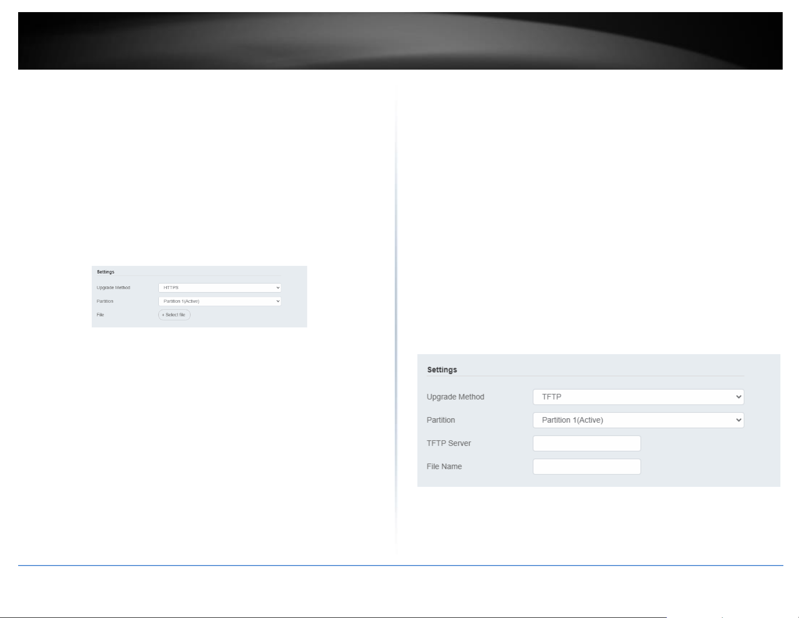
© Copyright 2022 TRENDnet. All Rights Reserved.
66
TRENDnet User’s Guide
Multi-Gig Web Smart Switch Series
Firmware Upgrade via HTTP Settings
Tools > Firmware > Firmware Upgrade
1. Log into your switch management page (see “Access your switch management page”
on page 5).
2. Click on Tools, click on Firmware, and click on Firmware Upgrade.
3. Select the firmware Upgrade Method (HTTPS or TFTP).
4. Select the Image you would like to upgrade to.
5. Select the location of the file by clicking Select file.
6. Navigate to the folder on your computer where the unzipped firmware file (.imag) is
located and select it.
5. Click Apply. If prompted, click Yes or OK.
Firmware Upgrade via TFTP Settings
Tools > Firmware Upgrade
Note: Before using this method, you will require a TFTP server. There are third party
TFTP server applications available for this function. If you are not familiar with the TFTP
protocol, it is recommended to use the HTTP method.
1. Log into your switch management page (see “Access your switch management page”
on page 5).
2. Click on Tools, click on Firmware Upgrade.
3. Make sure your TFTP server is running and note the IP address of your server and
firmware file name. The TFTP server should be in the same IP subnet as the switch.
Note: It is recommended to that the firmware file (.hex) is placed in your TFTP server
root directory.
5. Review the settings. Click Apply to start the firmware upgrade.
• Upgrade Method: Select TFTP to update the firmware via TFTP
• Partition: Select which image to update the firmware
• TFTP Server: Enter the IP address of your TFTP server.
• File Name: Enter the firmware filename with extension. (.hex)
6. Click Apply to start the firmware upgrade.
Dual Image
Tools > Firmware > Dual Image
Page 81
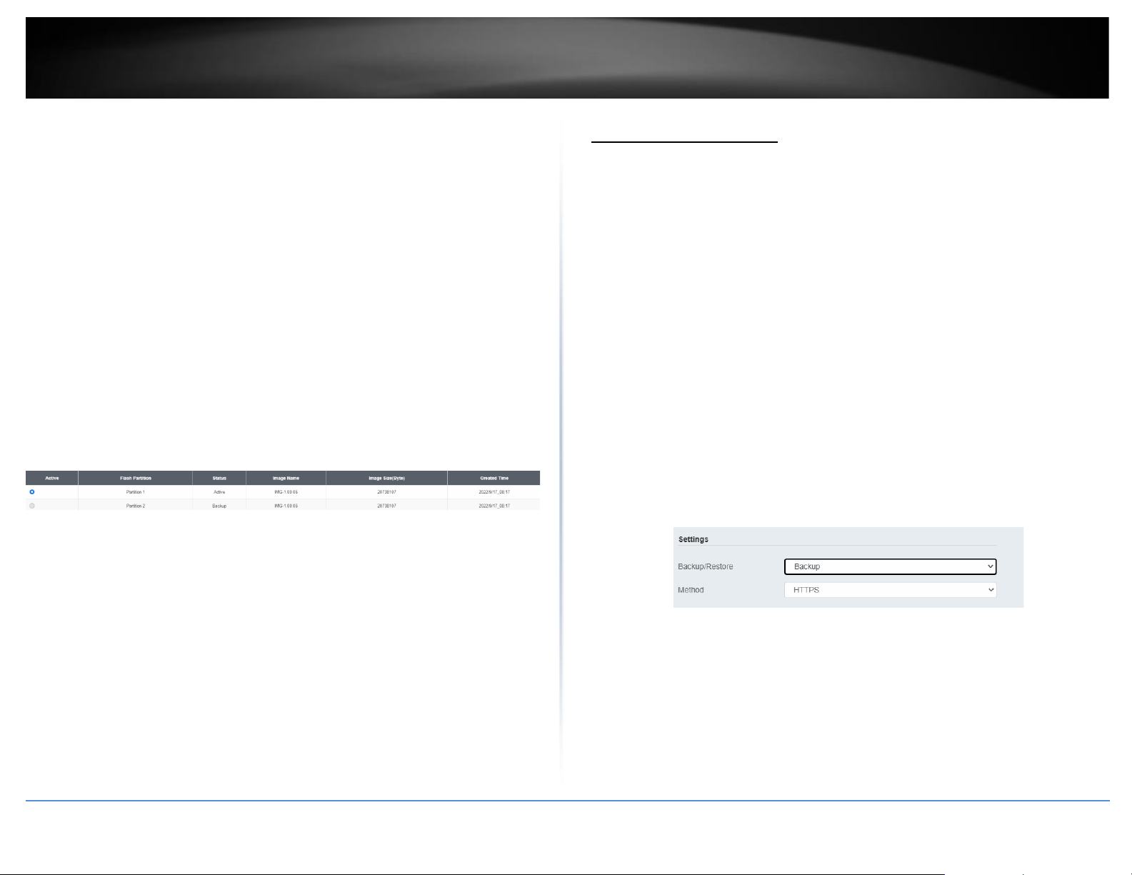
© Copyright 2022 TRENDnet. All Rights Reserved.
67
TRENDnet User’s Guide
Multi-Gig Web Smart Switch Series
Select the image to bootup on your switch from the next power cycle.
1. Log into your switch management page (see “Access your switch management page”
on page 5).
2. Click on Tools, click on Firmware, and click on Dual Image.
3. Review the settings. Click Apply to apply the changes and Save to save the changes.
•
Active: Displays the current Partition Image that is running on the
switch. You may select a different partition to boot up with here.
•
Flash Partition: Name of partition
•
Status: Displays the status of a partition. A partition that is currently
running will display Active, while one that is in standby will display
Backup.
•
Image Name: Firmware name of the partition
•
Image Size: Size of the firmware that is loaded on each partition
•
Created Time: When the firmware was loaded onto the partition
Config Backup Restore
Config Backup/Restore
Tools > Firmware > Backup/Restore
You may have added many customized settings to your switch and in the case that you
need to reset your switch to default, all your customized settings would be lost and
would require you to manually reconfigure all of your switch settings instead of simply
restoring from a backed up switch configuration file. The configuration will be backed up
or restored only to the currently used image.
Backup/Restore via HTTP Settings
To backup your switch configuration:
1. Log into your switch management page (see “Access your switch management page”
on page 5).
2. Click on Tools, click on Firmware and click on Backup/Restore.
3. Click Backup to save the configuration file (.cfg) to your local hard drive. Startup-
config refers to the configuration that was used to startup this switch.
Note: If prompted, choose the location on your local hard drive. If you are not prompted,
the configuration file (.cfg) will be saved to your default downloads folder.
To restore your switch configuration:
1. Log into your switch management page (see “Access your switch management page”
on page 5).
2. Click on Tools, click on Firmware and click on Backup/Restore.
Page 82
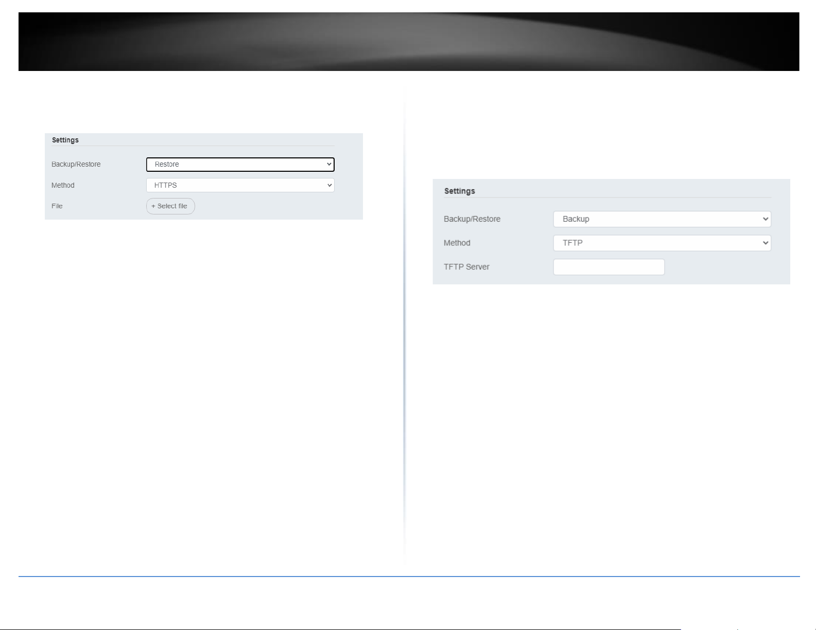
© Copyright 2022 TRENDnet. All Rights Reserved.
68
TRENDnet User’s Guide
Multi-Gig Web Smart Switch Series
3. Select Restore under Backup/Restore
Next to Select File, depending on your web browser, click on Browse or Choose File.
4. A separate file navigation window should open.
5. Select the switch configuration file to restore and click Restore. (Default File
Extension: .cfg). Click Apply to restore the settings,
6. Wait for the switch to restore settings.
Backup/Restore via TFTP Settings
Note: Before using this method, you will require a TFTP server. There are third party
TFTP server applications available for this function. If you are not familiar with the TFTP
protocol, it is recommended to use the HTTP method.
To backup your switch configuration:
1. Log into your switch management page (see “Access your switch management page”
on page 5).
2. Click on Tools, click on Firmware and click on Backup/Restore.
3. Make sure your TFTP server is running and note the IP address of your server and
firmware file name. The TFTP server should be in the same IP subnet as the switch.
4. Review the settings. Click Backup to save the configuration file (config.bin) to your
local hard drive on your TFTP server root directory.
• Backup/Restore: Select Backup to backup your configurations
• Method: Select TFTP as the method of backing up your configuration
• TFTP Server IP: Enter the IP address of your TFTP server.
To restore your switch configuration:
1. Log into your switch management page (see “Access your switch management page”
on page 5).
2. Click on Tools, click on Firmware and click on Backup/Restore.
3. Make sure your TFTP server is running and note the IP address of your server and
configuration file name. The TFTP server should be in the same IP subnet as the switch.
Note: It is recommended to put the configuration file (config.bin) is placed in your TFTP
server root directory.
4. Review the settings. Click Restore to restore the switch configuration file (config.bin)
from your local hard drive from your TFTP server root directory.
• Backup/Restore: Select Restore to restore your configurations
• Method: Select TFTP as the method of restoring up your configuration
• TFTP Server IP: Enter the IP address of your TFTP server
Page 83
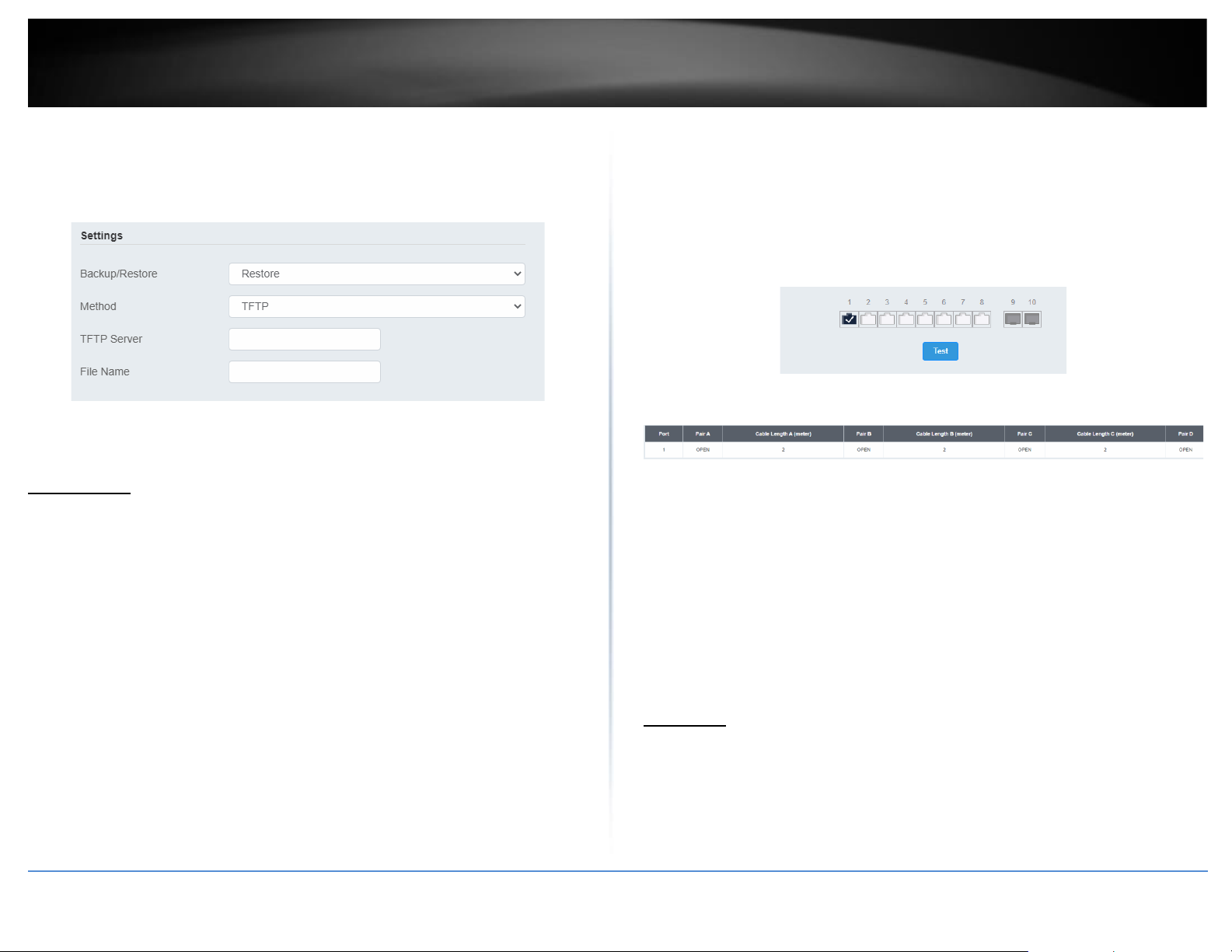
© Copyright 2022 TRENDnet. All Rights Reserved.
69
TRENDnet User’s Guide
Multi-Gig Web Smart Switch Series
• TFTP Server IP: Enter the IP address of your TFTP server.
• Config File Name: Enter the configuration file name to restore. (Default file
extension: .cfg)
5. Click Apply and wait for the switch to restore settings.
Diagnostics
Cable Diagnostics Test
Tools > Diagnostics
The switch provides a basic cable diagnostic tool in the GUI for verifying the pairs in
copper cabling and estimated distance for troubleshooting purposes.
Note:
1. If the cable length displays N/A, it means that the cable length is Not
Available. The may be due to the port being unable to determine the estimated
cable length. If length is displayed as “N/A” it means the cable length is “Not
Available”. This is due to the port being unable to obtain cable length/either
because its link speed is 10M or 100M, or the cables used are broken and/or of
bad in quality.
2. The deviation of “Cable Fault Distance” is +/- 2 meters. No cable may be
displayed in the table when the cable is less than 2 meters in length.
3. The test also measures the cable fault and identifies the fault in length
according to the distance from the switch.
1. Log into your switch management page (see “Access your switch management page”
on page 5).
2. Click on Tools and click on Cable Diagnostic.
3. Select the Port from the switch to run the cable diagnostic and click Test to run the
test.
The results will be displayed in the Cable Diagnostic Table below.
• Test Results: Displays the diagnostic results for each pair in the cable. One of
the following cable status parameters is displayed:
• OK: There is no problem detected with the cable.
• Open in Cable: There is an open wire within the cable.
• Short in Cable: Two wires are shorted together within the cable.
• Cross talk in Cable: There is crosstalk detected between one pair
• of wires and another pair within the cable.
Ping Test
Network Connectivity Test (Ping Tool)
Tools > Diagnostics > Ping Test
This chapter provides the procedure to ping a node on your network from the switch.
This procedure is useful in determining whether an active link exists between the switch
and another network device.
Page 84
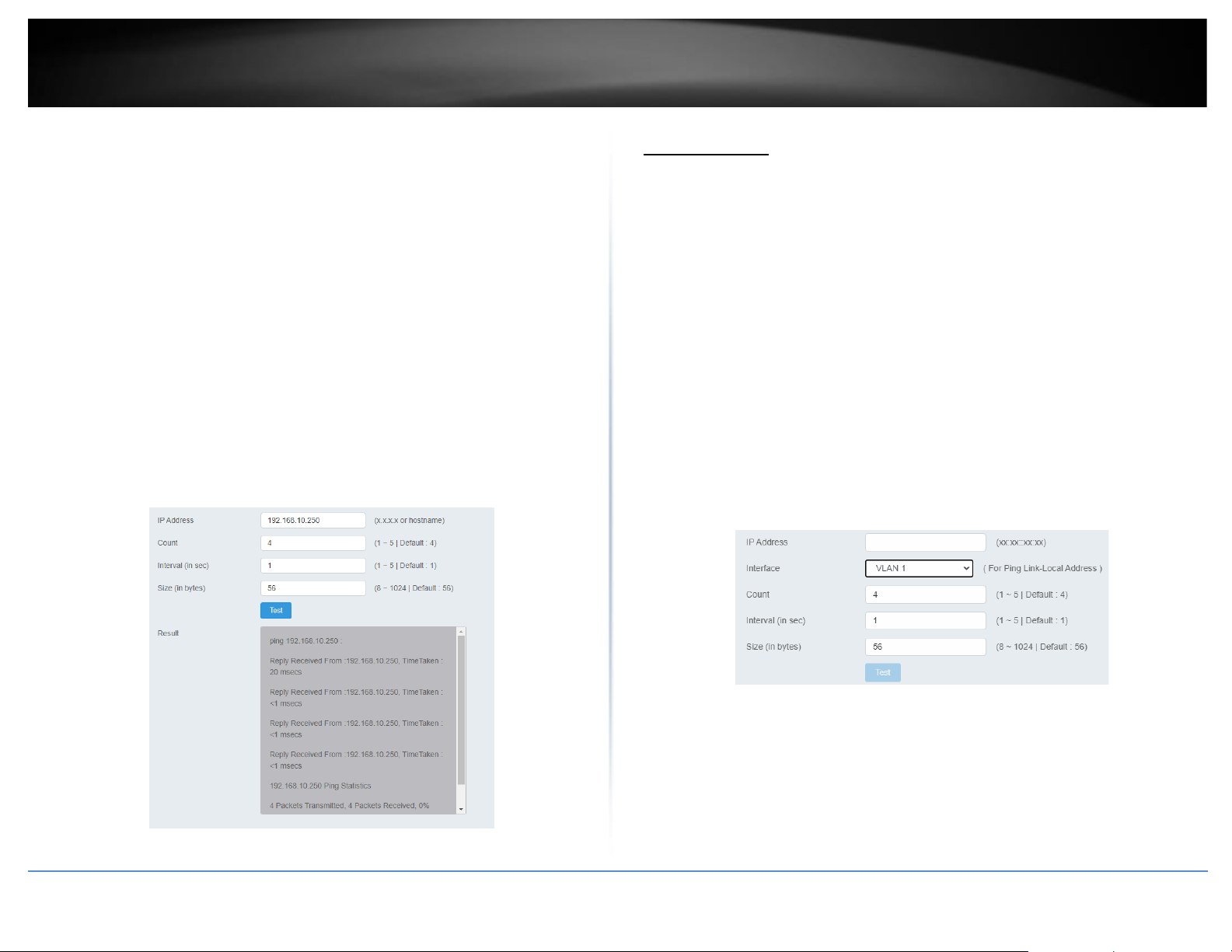
© Copyright 2022 TRENDnet. All Rights Reserved.
70
TRENDnet User’s Guide
Multi-Gig Web Smart Switch Series
The device you are pinging must be a member of the Default VLAN and within the same
local area network as your switch. In other words, the port on the switch through which
the node is communicating with the switch must be an untagged or tagged member of
the Default VLAN.
1. Log into your switch management page (see “Access your switch management page”
on page 5).
2. Click on Tools, click on Diagnostics, and click on Ping Test.
3. Review the settings. Click Start to start the network connectivity ping test. After the
ping test is activate, you can click Show Ping Results to check the ping test result.
• IP Address - The IP address of the node you want to ping in the IPv4 or IPv6
format.
• Count – Specifies the number of ping requests you want the switch to perform.
• Interval – Specifies the time between each ping request.
• Size – Specifies the size of the packet sent with each ping.
IPv6 Ping Test
Network Connectivity Test (Ping Tool)
Tools > Diagnostics > IPv6 Ping Test
1. Log into your switch management page (see “Access your switch management page”
on page 5).
2. Click on Tools, click on Diagnostics, and click on IPv6 Ping Test.
3. Review the settings. Click Start to start the network connectivity ping test. After the
ping test is activate, you can click Show Ping Results to check the ping test result.
• IP Address - The IP address of the node you want to ping in the IPv6 format.
• Interface – Select the appropriate VLAN ID
• Count – Specifies the number of ping requests you want the switch to perform.
• Interval – Specifies the time between each ping request.
• Size – Specifies the size of the packet sent with each ping.
Page 85
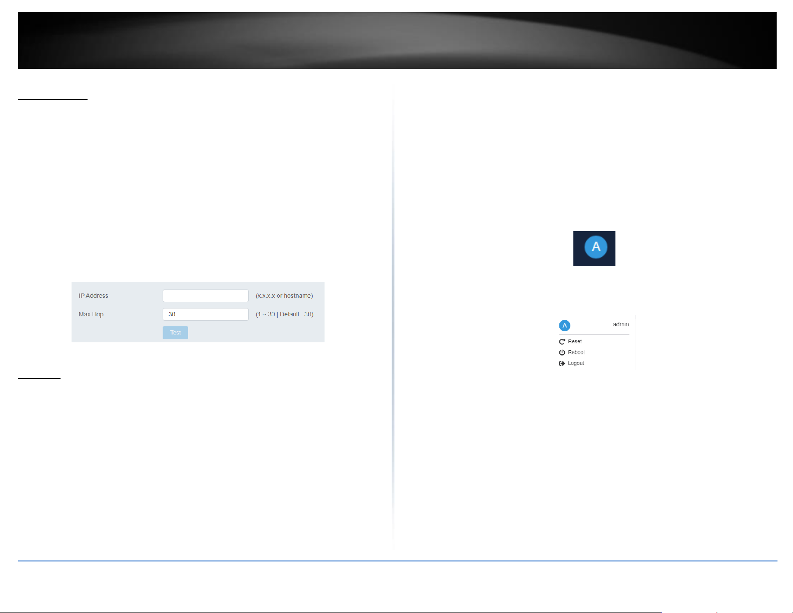
© Copyright 2022 TRENDnet. All Rights Reserved.
71
TRENDnet User’s Guide
Multi-Gig Web Smart Switch Series
Trace Route
Tools > Diagnostics > Trace Route
1. Log into your switch management page (see “Access your switch management page”
on page 5).
2. Click on Tools, click on Diagnostics, and click on Trace Route.
3. Review the settings. Click Test to start the Trace Route. After the test is completed,
you can see the result below the test.
•
IP Address - The IP address of the node you want to ping in the IPv6 format.
•
Max Hop – Enter the maximum number of hops
Reboot
Reboot/Reset to factory defaults
Tools > Reboot
This section provides the procedures for rebooting or resetting the switch to factory
default settings.
To reboot your switch:
You may want to reboot your switch if you are encountering difficulties with your switch
and have attempted all other troubleshooting.
Note: You may want to save the settings to flash before reboot the switch under Save
Settings to Flash (menu) > Save Settings to Flash (button). If you have not saved your
current configuration settings to flash first, the configuration changes will be lost after a
reboot.
There are two methods that can be used to reboot your switch.
• Hardware Method: Using a paper clip, on the front panel of the switch, push
and hold the Reset button between 1~5 seconds and release.
• Software Method (Switch Management Page):
1. Log into your switch management page (see “Access your switch management page”
on page 5).
2. Click on your profile in the top right corner.
3. Click Reboot drop-down list. Wait for the switch complete the rebooting process.
To reset your switch to factory defaults:
You may want to reset your switch to factory defaults if you are encountering difficulties
with your switch and have attempted all other troubleshooting. Before you reset your
switch to defaults, if possible, you should backup your switch configuration first, see
“Backup/Restore” on page 88.
There are two methods that can be used to reset your switch to factory defaults.
• Hardware Method: Using a paper clip, on the front panel of the
switch, push and hold the Reset button more than 6 seconds and
release. Located on the front panel of your switch, see “Product
Page 86
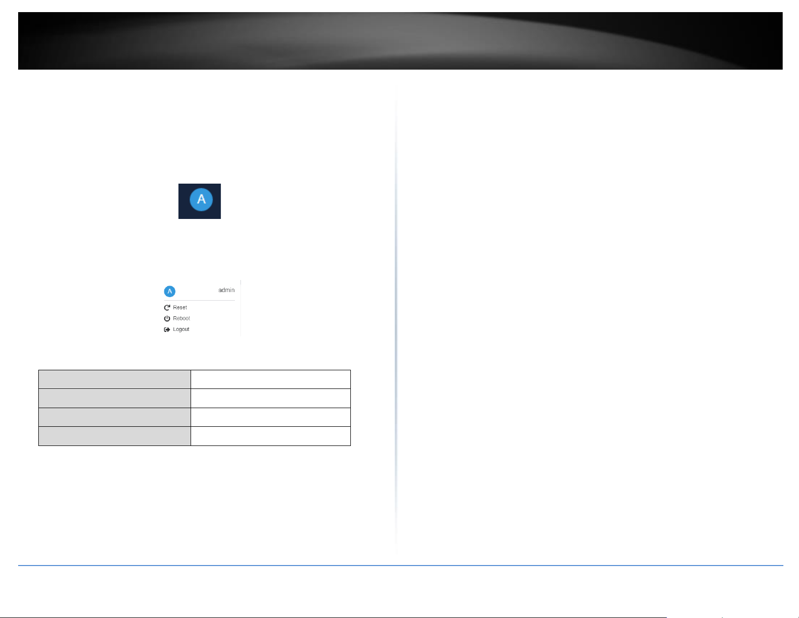
© Copyright 2022 TRENDnet. All Rights Reserved.
72
TRENDnet User’s Guide
Multi-Gig Web Smart Switch Series
Hardware Features” on page 2. Use this method if you are
encountering difficulties with accessing your switch management
page.
• Software Method (Switch Management Page):
1. Log into your switch management page (see “Access your switch management page”
on page 5).
2. Click on your profile in the top right corner.
3. Click Reset from the drop-down list. Clicking Reset, will automatically reset the switch
back to its factory default settings.
The switch’s factory default settings are below.
Administrator User Name
admin
Administrator Password
admin
Switch IP Address
192.168.10.200
Switch Subnet Mask
255.255.255.0
Page 87
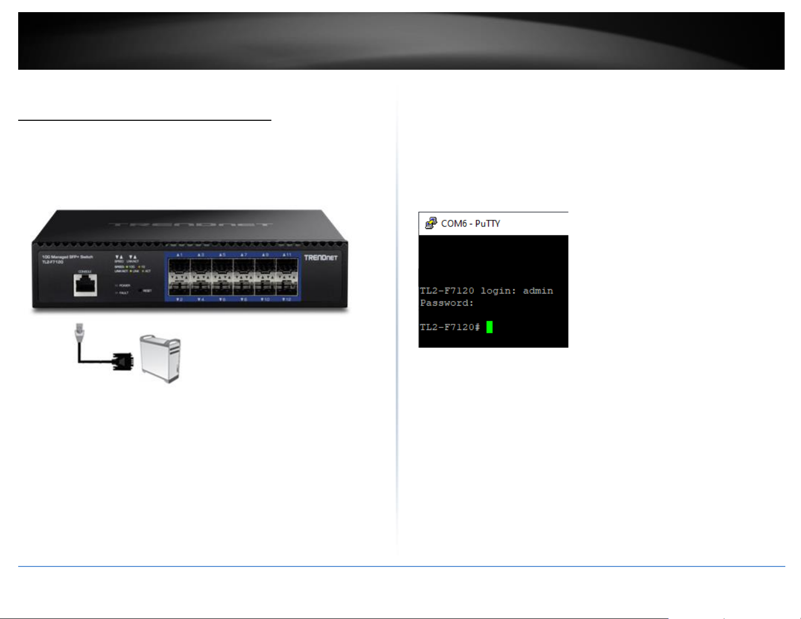
© Copyright 2022 TRENDnet. All Rights Reserved.
73
TRENDnet User’s Guide
Multi-Gig Web Smart Switch Series
Command Line Interface Reference
Access your switch command line interface
Note: The system may be managed out-of-band through the console port. The console
port is a female RJ-45 port and the included RJ-45 male to RS-232 serial DB-9 female
console cable.
1. Using the included RJ-45 to RS-232 serial DB-9 cable, connect the RJ-45 end to the
switch console port and connect the RS-232 end to your computer RS-232 DB-9 male
port.
2. On your computer, run the terminal emulation program (ex. HyperTerminal,
TeraTerm, putty etc.).
3. Select the appropriate COM port used for connecting to the switch console.
4. Use the following settings for the connection.
• Data Rate: 115200 bps
• Data Bit: 8 bits
• Parity: None
• Stop Bits: 1
• Flow Control: None
• Emulation mode: VT100
5. After you have setup all of the parameters appropriately, the terminal emulation
window should display a prompt for user name and password.
Enter the user name and password. By default:
User Name: admin
Password: admin
Note: User Name and Password are case sensitive.
You can also use Telnet or SSH protocols to access the switch command line interface
using IP address.
Page 88

© Copyright 2022 TRENDnet. All Rights Reserved.
74
TRENDnet User’s Guide
Multi-Gig Web Smart Switch Series
Command
Mode
Access Method
Pro
mpt
Privileged
EXEC
This is the initial
mode to start a
session.
<Switch Name>#
Global
Configuratio
n
The EXEC mode command
configure terminal is used
to
enter the Global
Configuration mode.
<Switch Name> (config)#
Interface
Configuratio
n
The Global
Configuration mode
command interface
<interfacetype><interfacei
d>
is used to enter
the Interface
configuration
mode.
<Switch Name> (config-if)#
Interface
Range
Mode
The Global
Configuration mode
command interface
range
( {
<interfacetype><slot/portport>}
{vlan <vlan-id(1-4094)><vlan-id(2- 4094)>}) is
used to enter the
Interface range mode.
<Switch Name> (config-if-range)#
SNTP
Configuratio
n
The SNTP Configuration
mode command sntp is
used to enter the SNTP
configuration mode.
<Switch Name> (config-sntp)#
Config-
VLAN
The Global
configuration mode
command vlan vlan-id
is used to enter the
Config-VLAN mode.
<Switch Name> (config-vlan)#
Page 89
© Copyright 2022 TRENDnet. All Rights Reserved.
75
TRENDnet User’s Guide
Multi-Gig Web Smart Switch Series
Line Configuration
The Line Configuration mode
command line cli is used to enter
the Line configuration mode.
<Switch
Name>
(configline)#
IPV4 ACL Extended
Access List Configuration
The IPV4 ACL Extended Access List
configuration mode command ip
access-list extended <name> is
used to enter the IPV4 ACL
Extended Access List configuration
mode.
<Switch
Name>
(configext-nacl)#
IPV6 ACL Extended
Access List Configuration
The IPV6 ACL Extended Access List
configuration mode command ipv6
access-list extended <name> is
used to enter the IPV6 ACL
Extended Access List configuration
mode.
<Switch
Name>
(configipv6-acl)#
MAC ACL Extended
Access List Configuration
The MAC ACL Extended Access List
configuration mode command mac
access-list extended <name> is
used to enter the MAC ACL
Extended Access List configuration
mode.
<Switch
Name>
(configext-macl)#
Policy Map
Configuration Mode
The Policy Map configuration mode
command class-policy <name> is
used to enter the Policy Map
configuration mode.
<Switch
Name>
(config-qcply)#
MSTP Configuration
Mode
The MSTP Configuration mode
command spanning-tree mst
configuration is used to enter the
MSTP configuration mode.
<Switch
Name>
(configmst)#
Page 90
Copyright 2023 TRENDnet. All Rights Reserved.
TRENDnet User’s Guide
Multi-Gig Web Smart Switch Series
Switch CLI User Manual
System
4.1.1 Help
Command Objective
This command displays a brief description for
the given command
Syntax
Help [ command ]
Mode
All Modes
4.1.1 Clear screen
Command Objective
This command clears all the contents from the
screen
Syntax
Clear screen
Mode
All Modes
4.1.1 End
Command Objective
Exit from configure mode
Syntax
End
Mode
All Modes
4.1.2 Logout
Command Objective
This command exits from Privileged EXEC/ User
EXEC mode to ISS Login Prompt in case of
console session. In case of a telnet session, this
command terminates the session.
Syntax
logout
Mode
Privileged EXEC Mode
4.1.3 Show privilege
Command Objective
Show current privilege level.
Syntax
Show privilege
Mode
Privileged EXEC Mode
4.1.3 Show CLI
Command Objective
This command displays TTY line information
such as EXEC timeout.
Syntax
Show cli
Mode
Privileged EXEC Mode
4.1.4 Exit
Command Objective
This command exits the current mode and
reverts to the mode used prior to the current
mode.
Syntax
exit
Mode
All Modes
4.1.5 Configure terminal
Command Objective
This command enters to Global Configuration
Mode which allows the user to execute all the
commands that supports global configuration
mode.
Syntax
Configure terminal
Mode
Privileged EXEC Mode
Page 91
Copyright 2023 TRENDnet. All Rights Reserved.
TRENDnet User’s Guide
Multi-Gig Web Smart Switch Series
4.1.6 listuser
Command Objective
This command lists all the default and newly
created users, along with their permissible
mode.
Syntax
listuser
Mode
Privileged EXEC Mode
4.1.7 Show users
Command Objective
This command displays the information about
the current user.
Syntax
Show users
Mode
Privileged EXEC Mode
4.1.8 lock
Command Objective
This command locks the CLI console. It allows
the user/system administrator to lock the
console to prevent unauthorized users from
gaining access to the CLI command shell. Enter
the login password to release the console lock
and access the CLI command shell.
Syntax
lock
Mode
Privileged EXEC Mode
4.1.9 show history
Command Objective
This command displays a list of recently
executed commands.
Syntax
Show history
Mode
Privileged EXEC Mode
4.1.10 username
Command Objective
This command creates a user and sets the
enable password for that user with the privilege
level.
The no form of the command deletes a user and
disables the enable password for that user.
Syntax
username <user-name> [password <passwd>]
[privilege <1-15>] no username < user-name >
Parameter Description
• <user-name> - Specifies the login user name
to be created.
• <passwd> - Specifies the password to be
entered by the user to login to the system. The
size password entered must be a minimum of 8
and maximum of 20 characters containing
atleast one uppercase, one lowercase, one
number and one special character.
• privilege <1-15> - Applies restriction to the
user for accessing the
CLI commands. This values ranges between 1
and 15. For Example, a user ID configured with
privilege level as four can access only the
commands having privilege ID lesser than or
equal to four.
Mode
Privileged EXEC Mode
4.1.1 set minimum password length
Command Objective
This command configures minimum password
length. If the given password has less than the
configured password length, it will not be
allowed This value ranges between 8 and 20.
Syntax
set minimum password length <minimum-len>
Mode
Global Configuration Mode
Page 92
Copyright 2023 TRENDnet. All Rights Reserved.
TRENDnet User’s Guide
Multi-Gig Web Smart Switch Series
4.1.2 line cli
Command Objective
This command identifies a specific line for
configuration and enters the line configuration
mode and allows the user to execute all the
commands that supports line configuration
mode
Syntax
Line cli
Mode
Global Configuration Mode
4.1.3 exec-timeout
Command Objective
This command sets a time (in seconds) for EXEC
line disconnection. This value ranges between 1
and 10000 seconds.
The no form of this command resets the EXEC
timeout to its default value.
Syntax
exec-timeout <integer (1-18000)>
no exec-timeout
Mode
Line Configuration Mode
4.1.11 ping
Command Objective
This command sends echo messages. The
Packet Internet Groper (Ping) module is built
based on the ICMP echo request and ICMP echo
response messages. The network administrator
uses this ping on a remote device to verify its
presence. Ping involves sending ICMP echo
messages repeated and measuring the time
between transmission and reception of
message. The output displays the time taken for
each packet to be transmitted, number of
packets transmitted, number of packets
received and packet loss percentage
The no form of this command resets the EXEC
timeout to its default value.
Syntax
ping [ ip ] {<ip_addr>|<string>} [ count
<integer(1-10)> ] [ size
<integer(36-2080)> ]
Parameter Description
• ip - Configures the IP address of the node to
be pinged.
• ipAddress - Configures the source IP address
of the node to be pinged.
• hostname - Configures the name of the host.
• count - Configures the number of times the
given node address is to be pinged.
• size - Configures the size of the data portion
of the PING PDU
Mode
Privileged EXEC Mode
4.1.12 traceroute
Command Objective
This command traces route to the destination.
The no form of this command resets the EXEC
timeout to its default value.
Syntax
traceroute {<ip_addr>|<string> | ipv6
<ip6_addr>} [max-ttl <short (2- 255)>]
Parameter Description
• <ip-address> - Configurest the destination IP
address to which a route has to be traced.
• <string> - Configurest the destination IP
hostname to which a
route has to be traced.
Page 93
Copyright 2023 TRENDnet. All Rights Reserved.
TRENDnet User’s Guide
Multi-Gig Web Smart Switch Series
• ipv6 <ip6_addr> - Configurest the
destination IPv6 address to which a route has to
be traced.
• [max-ttl <short (2-255)>] -Configures the
maximum value of the TTL field to be filled up in
the IP packets used for the trace route.
Mode
Privileged EXEC Mode
4.1.13 clear counters
Command Objective
This command clears all the current interface
counters from the interface unless the optional
arguments type and number are specified to
clear only a specific interface type (serial,
Ethernet, Token Ring, and so on).
Syntax
clear counters [ <interface-type> <interface-id>
]
Parameter Description
• <interface-type>- Configures the specified
type of interface.
• <interface-id> - Configures the IP interface
configuration for the specified interface
identifier. This is a unique value that represents
the specific interface. This value is a
combination of slot number and port number
separated by a slash. For Example: 0/1
represents that the slot number is 0 and port
number is 1.
Mode
Privileged EXEC Mode
4.1.14 jumbo-frame
Command Objective
This command configures the maximum
transmission unit frame size for all the frames
transmitted and received on all the interfaces in
a switch. The size of the jumbo frame size can
be increased using this command. The value
ranges between 1522 and 9216. The no form of
this command sets the maximum transmission
unit to the default value in all interfaces. This
value defines the largest PDU that can be
passed by the interface without any need for
fragmentation. This value is shown to the
higher interface sub-layer and should not
include size of the encapsulation or header
added by the interface.
The no form of this command resets the EXEC
timeout to its default value.
Syntax
jumbo-frame <frame-size(1522-9216)>
Mode
Global Configuration Mode
4.1.15 interface range
Command Objective
This command selects the range of physical
interfaces and VLAN interfaces to be
configured.
The no form of the command selects the range
of VLAN interfaces to be removed.
Syntax
interface range ( { <interface-type> <slot/portport>} {vlan <vlan- id(1-4094)> - <vlan-id(2-
4094)>})
no interface range vlan <vlan-id(1-4094)> -
<vlan-id(2-4094)>
Parameter Description
• <interface-type> - Selects the range of the
specified interface.
• <slot/port-port> - Selects the range of the
specified interface identifier. This is a unique
value that represents the specific interface. This
value is a combination of slot number and port
number separated by a slash.
Page 94
Copyright 2023 TRENDnet. All Rights Reserved.
TRENDnet User’s Guide
Multi-Gig Web Smart Switch Series
• vlan <vlan-id(1-4094)> - <vlan-id(2-4094)> Selects the range of the specified VLAN ID. This
is a unique value that represents the specific
VLAN created and activated. This value ranges
between 1 and 4094.
Mode
Global Configuration Mode
4.1.1 configure
Command Objective
This command enters the configuration mode.
Configuration from memory or network is not
supported, when entered into the configuration
mode using this command.
Syntax
configure
Mode
Privileged EXEC Mode
4.1.2 mac-address-table static unicast
Command Objective
This command configures a static unicast MAC
address in the forwarding database.
The no form of the command deletes a
configured static Unicast MAC address from the
forwarding database.
Syntax
mac-address-table static unicast
<aa:aa:aa:aa:aa:aa> vlan <vlan-id > interface
([<interface-type> <0/a-b, 0/c, ...>] [<interfacetype> <0/a-b, 0/c, ...>] [port-channel <a,b,c-d>])
no mac-address-table static unicast
<aa:aa:aa:aa:aa:aa> vlan <vlan-id >
Parameter Description
• <aa:aa:aa:aa:aa:aa> - Configures the static
unicast destination MAC address. The received
packets having the specified MAC address are
processed.
• vlan <vlan-id> - Configures the static unicast
destination
MAC address for the specified VLAN. This value
ranges between 1 and 4094.
• <vlan –id> - VLAN ID is a unique value that
represents the specific VLAN. This value ranges
between 1 and 4094
• interface - Configures the member ports
interface type and
ID. The details to be provided are:
• <interface-type> - Configures the member
ports for the specified type of interface. The
interface can be:
•gigabitethernet – A version of LAN standard
architecture that supports data transfer up to 1
Gigabit per second.
• port-channel – Logical interface that
represents an aggregator which contains
several ports aggregated together.
• <0/a-b, 0/c, ...> - Configures the member
ports for the specified interface identifier. This
is a unique value that represents the specific
interface. This value is a combination of slot
number and port number separated by a slash.
Port-channel ID is provided, for interface type
port-channel. Use comma as a separator
without space while configuring list of
interfaces.
Example: 0/1, 0/3 or 1, 3.
Mode
Global Configuration Mode
4.1.16 mac-address-table aging-time
Command Objective
This command configures the timeout period
(in seconds) for aging out dynamically learned
Page 95
Copyright 2023 TRENDnet. All Rights Reserved.
TRENDnet User’s Guide
Multi-Gig Web Smart Switch Series
forwarding information entry and static entry in
the MAC address table. That is, the entry is
deleted once the aging timer expires. High
value for the aging time helps to record
dynamic entries for a longer time, if traffic is
not frequent. This reduces the possibility of
flooding.
The no form of the command resets the
maximum age of an entry in the MAC address
table to its default value.
Syntax
mac-address-table aging-time <10-630
seconds> no
mac-address-table aging-time
Mode
Global Configuration Mode/ Switch
Configuration Mode
4.1.17 set switch-name
Command Objective
This command sets the name of the switch..
Syntax
set switch-name <switchname>
Mode
Global Configuration Mode
4.1.18 set ip http
Command Objective
This command enables/disables HTTP in the
switch.
Syntax
set ip http {enable | disable}
Parameter Description
• enable - Enables HTTP in the switch.
• disable - Disables HTTP in the switch.
Mode
Global Configuration Mode
4.1.19 ip telnet service
Command Objective
This command enables the telnet service in the
system. The no form of this command disables
the telnet service.
Syntax
ip telnet service no
ip telnet service
Mode
Global Configuration Mode
4.1.20 copy startup-config
Command Objective
This command copies a file from a source
remote site /flash to a destination remote
site/flash. The entire copying process takes
several minutes and differs from protocol to
protocol and from network to network.
Syntax
copy startup-config { tftp://ip-address/filename
}
Parameter Description
•tftp://ip-address/filename - Configures the
TFTP details for taking back up of initial
configuration in TFTP server.
■ ip-address - The IP address or host
name of the server.
■ filename - The name of the file in
which the initial configuration should
be stored. Filenames and directory
names are case sensitive
Mode
Privileged EXEC Mode
4.1.21 copy
Command Objective
This command copies the configuration from a
remote site to flash.
Syntax
copy { tftp://ip-address/filename startupconfig}
Page 96
Copyright 2023 TRENDnet. All Rights Reserved.
TRENDnet User’s Guide
Multi-Gig Web Smart Switch Series
Parameter Description
• tftp://ip-address/filename startup-config Configures the address from which the file is to
be copied and the file name from which
configuration is to be copied. This option
configures the TFTP server details Filenames
and directory names are case sensitive
Mode
Privileged EXEC Mode
4.1.22 save
Command Objective
This command copies variables from the
running configuration to the startup
configuration file in NVRAM, where the
running-config is the current configuration in
the router and the startup config is the
configuration that is loaded when the switch
boots up.
Syntax
save
Mode
Privileged EXEC Mode
4.1.23 copy logs
Command Objective
This command writes the system logs to a
remote site.
Syntax
copy logs { tftp://ip-address/filename }
Parameter Description
• tftp://ip-address/filename startup-config Configures the address from which the file is to
be copied and the file name from which
configuration is to be copied. This option
configures the TFTP server details Filenames
and directory names are case sensitive
Mode
Privileged EXEC Mode
4.1.24 clock set
Command Objective
This command manages the system clock.
Syntax
clock set hh:mm:ss <day (1-31)>
{january|february|march|april|may|june|july|
august|september|oct
ober|november|december} <year (2000 -
2035)>
Parameter Description
• hh:mm:ss - Sets the current time. The format
is hour, minutes and seconds.
■ <day (1-31)> - Sets the current day. It ranges
between 1 and 31.
■ january - Sets the month as January.
■ february - Sets the month as February
■ march - Sets the month as march
■ april - Sets the month as april
■ may - Sets the month as may
■ june - Sets the month as June
■ july - Sets the month as July
■ august - Sets the month as August
■ september - Sets the month as September
■ october - Sets the month as October
■ november - Sets the month as November
■ december - Sets the month as December
■ <year (2000 - 2035)> - Sets the year. It ranges
between 2000 and 2035
Mode
Global Configuration Mode
4.1.25 show clock
Command Objective
This command displays the system date and
time.
Syntax
Show clock
Page 97
Copyright 2023 TRENDnet. All Rights Reserved.
TRENDnet User’s Guide
Multi-Gig Web Smart Switch Series
Mode
Privileged EXEC Mode
4.1.26 show jumbo-frame
Command Objective
This command displays the maximum
transmission unit frame size for all the frames
transmitted and received on all the interfaces in
a switch.
Syntax
show jumbo-frame
Mode
Privileged EXEC Mode
4.1.27 show system information
Command Objective
This command displays system information.
Syntax
show system information
Mode
Privileged EXEC Mode
4.1.28 reboot
Command Objective
This command restarts the switch.
Syntax
reboot
Mode
Privileged EXEC Mode
4.1.29 restore-defaults
Command Objective
This command restore default configuration.
Syntax
restore-defaults
Mode
Privileged EXEC Mode
4.1.1 show telnet server
Command Objective
This command displays the telnet server status.
Syntax
show telnet server
Mode
Privileged EXEC Mode
4.1.2 show telnet server
Command Objective
This command displays the http server status
and HTTP port.
Syntax
reboot
Mode
Privileged EXEC Mode
4.1.30 port speed - duplex
Command Objective
This command configures the speed and duplex
operation.
Syntax
speed { 10 | 100 | 1000 | 10000 } duplex { full |
half }
Parameter Description
• 10 - Port runs at 10Mbps
• 100 - Port runs at 100Mbps
• 1000 - Port runs at 1000Mbps
• 10000 - Port runs at 10000Mbps
• full - Port is in full-duplex mode, that is data
simultaneously communicates in both
directions.
• half - Port is in half-duplex mode, that is data
can communicate in
both directions, but only in one direction at a
time.
Mode
Interface Configuration
4.1.31 negotiation
Command Objective
This command enables auto-negotiation on the
interface.
Page 98
Copyright 2023 TRENDnet. All Rights Reserved.
TRENDnet User’s Guide
Multi-Gig Web Smart Switch Series
The no form of the command disables autonegotiation on the interface.
The port in which auto-negotiation is enabled,
negotiates with the other end for port
properties like speed, duplexity and so one. The
normal port uses the port property values
configured by the administrator.
Syntax
negotiation no
negotiation
Mode
Interface Configuration
4.1.32 port-isolation
Command Objective
This command set the status of the traffic to be
allowed in these configured egress ports when
the ingress is this interface.
Syntax
port-isolation {enable|disable}
Parameter Description
• enabled - Enables the Port Isolation rule in
this ingress interface.
• disabled - Disables the Port Isolation rule in
this ingress interface.
Mode
Interface Configuration
4.1.33 show port-isolation status
Command Objective
This command displays the Port Isolation table.
Syntax
show port-isolation status
Mode
Privileged EXEC Mode
4.1.34 clock utc-offset
Command Objective
This command sets the system time zone with
respect to UTC.
The no form of command resets the system
time zone to GMT.
Syntax
clock utc-offset <UTC-offset value as (+HH:MM
/-HH:MM)(+00:00 to
+14:00)/ (-00:00 to -12:00)> Eg: +05:30
Parameter Description
• +/- - Sets the client time zone as after or
before UTC. Plus indicates forward time zone
and minus indicates backward time zone.
• UTC- offset value as - Sets the UTC offset
value in hours.
- +00:00 to +14:00
- -00:00 to -12:00
Mode
Global Configuration Mode
4.1.35 show clock properties
Command Objective
This command displays the PTP clock
properties.
Syntax
show clock properties
Mode
Privileged EXEC Mode
4.1.36 interface
Command Objective
This command allows to configure interface
such as VLAN.
Syntax
interface {vlan < vlan-id > [switch <string(32)>] |
port-channel <integer (1-8)> | <iftype>
<ifnum>}
no interface {vlan < vlan-id > [switch
<string(32)>] | port-channel
<integer (1-8)> | <iftype> <ifnum>}
Page 99
Copyright 2023 TRENDnet. All Rights Reserved.
TRENDnet User’s Guide
Multi-Gig Web Smart Switch Series
Parameter Description
• vlan <vlan-id> - VLAN ID is a unique value
that represents the specific VLAN. This value
ranges between 1 and 4094.
• switch<switch-name>- Configures interface
for the specified context. This value represents
unique name of the switch context. This value is
a string whose maximum size is 32. This
parameter is specific to multiple instance
feature. This feature has been included to
adhere to the Industry Standard CLI syntax.
• port-channel<port-channel-id (1-8)>Configures the port to be used by the host to
configure the router. This value ranges between
1 and 8. The port channel identifier can be
created or port channel related configuration
can done, only if the LA feature is enabled in
the switch.
• <interface-type>- Configures the specified
type of interface.
■ gigabitethernet – A version of LAN
standard architecture that supports
data transfer upto 1 Gigabit per
second.
■ port-channel – Logical interface that
represents an aggregator which
contains several ports aggregated
together.
Mode
Global Configuration Mode
4.1.37 ip address
Command Objective
This command sets the IP address for an
interface.
Syntax
ip address <ucast_addr> <ip_mask>
no ip address <ucast_addr>
Parameter Description
• ucast_addr - Sets the IP address for an
interface. If the network in which the switch is
implemented contains a server such as DHCP
server, dynamically allocating IP address, the
configured IP address should not be within the
range of the addresses that will be allocated by
the server to the other switches.
• ip_mask - Sets the subnet mask for the
configured IP address. The configured subnet
mask should be in the same subnet of the
network in which the switch is placed.
Mode
Interface Configuration Mode
This command is applicable in VLAN Interface
Mode / OOB Interface Mode.
4.1.38 ip address
Command Objective
This command sets the DHCP/BOOTP IP address
for an interface.
Syntax
ip address dhcp
ip address bootp
no ip address
Parameter Description
•dhcp – Get IP by using DHCP protocol.
•botp – Get IP by using BOOTP protocol.
Mode
Interface Configuration Mode
4.1.1 shutdown
Command Objective
Set the AdminStatus of Interface down/up.
Syntax
shutdown
no shutdown
Parameter Description
Set the AdminStatus of Interface down/up.
Page 100
Copyright 2023 TRENDnet. All Rights Reserved.
TRENDnet User’s Guide
Multi-Gig Web Smart Switch Series
Mode
Interface Configuration Mode
4.1.2 description
Command Objective
Descriptions about the interface.
Syntax
description <description of this interface>
no description
Description
Descriptions about the interface. Or
Cancel the descriptions about the interface.
Mode
Interface Configuration Mode
4.1.39 description
Command Objective
This command shows the maximum number of
learning address and lock mode.
Syntax
show interface port-security [<iftype> <ifnum>]
Parameter Description
• <interface-type> - Displays the IP interface
configuration for the specified type of interface.
The interface can be:
■ gigabitethernet – A version of LAN
standard architecture that supports
data transfer upto 1 Gigabit per
second.
Mode
Privileged EXEC Mode
4.1.10 show interface cable-diag
Command Objective
Used to diagnose the copper cable. If there is
an error on the cable, it can determine the type
of error and the position where the error
occurred.
Syntax
show interface cable-diag Gigabitethernet
[<iftype> <ifnum>]
Parameter Description
• OK- This pair has been connected to partner
network device and the link is up.
OPEN–This pair is left open.
SHORT–This pair has been shorted between
two lines of its own. Unknown–The last
diagnosis do not obtain the cable’ status, please
try it again.
Mode
Privileged EXEC Mode
4.1.11 show ip interface
Command Objective
This command displays the IP interface
configuration.
Syntax
show ip interface [{[Vlan <vlan-id(1-4094)> |
[<interface- type><interface-id>]
Parameter Description
• Vlan<vlan-id(1-4094)> - Displays the IP
interface configuration for the
specified VLAN ID. This is a unique value that
represents the specific VLAN created. This value
ranges between 1 and 4094.
• <interface-type> - Displays the IP interface
configuration for the
specified type of interface. The interface can
be:
■ gigabitethernet – A version of LAN
standard architecture that supports
data transfer upto 1 Gigabit per
second.
•<interface-id> - Displays the IP interface
configuration for the specified interface
identifier. This is a unique value that represents
the specific interface. This value is a
 Loading...