

Page 1

TE100-DM/DS Series
Dual-Speed Hub
User’s Guide
Rev. 01 (May, 1998)
6012-0165001
Printed In Taiwan
RECYCLABLE
Page 2

Wichtige Sicherheitshinweise
1. Bitte lesen Sie sich diese Hinweise sorgf? tig durch.
2. Heben Sie diese Anleitung f? den sp? ern Gebrauch auf.
3. Vor jedem Reinigen ist das Ger? vom Stromnetz zu trennen. Vervenden Sie keine Fl? sigoder Aerosolreiniger. Am besten dient ein angefeuchtetes Tuch zur Reinigung.
4. Um eine Besch? igung des Ger? es zu vermeiden sollten Sie nur Zubeh? teile verwenden,
die vom Hersteller zugelassen sind.
5. Das Ger? is vor Feuchtigkeit zu sch? zen.
6. Bei der Aufstellung des Ger? es ist auf sichern Stand zu achten. Ein Kippen oder Fallen k?
nte Verletzungen hervorrufen. Verwenden Sie nur sichere Standorte und beachten Sie die
Aufstellhinweise des Herstellers.
7. Die Bel? tungs? fnungen dienen zur Luftzirkulation die das Ger? vor ? erhitzung sch? zt.
Sorgen Sie daf? , daß diese ? fnungen nicht abgedeckt werden.
8. Beachten Sie beim Anschluß an das Stromnetz die Anschlu? erte.
9. Die Netzanschlu? teckdose muß aus Gr? den der elektrischen Sicherheit einen
Schutzleiterkontakt haben.
10. Verlegen Sie die Netzanschlu? eitung so, daß niemand dar? er fallen kann. Es sollete auch
nichts auf der Leitung abgestellt werden.
11. Alle Hinweise und Warnungen die sich am Ger? en befinden sind zu beachten.
12. Wird das Ger? ? er einen l? geren Zeitraum nicht benutzt, sollten Sie es vom Stromnetz
trennen. Somit wird im Falle einer ? erspannung eine Besch? igung vermieden.
13. Durch die L? tungs? fnungen d? fen niemals Gegenst ? de oder Fl? sigkeiten in das Ger?
gelangen. Dies k? nte einen Brand bzw. Elektrischen Schlag ausl? en.
14. ? fnen Sie niemals das Ger? . Das Ger? darf aus Gr? den der elektrischen Sicherheit nur
von authorisiertem Servicepersonal ge? fnet werden.
15. Wenn folgende Situationen auftreten ist das Ger? vom Stromnetz zu trennen und von einer
qualifizierten Servicestelle zu ? erpr? en:
a– Netzkabel oder Netzstecker sint besch? igt.
b– Fl? sigkeit ist in das Ger? eingedrungen.
c– Das Ger? war Feuchtigkeit ausgesetzt.
d– Wenn das Ger? nicht der Bedienungsanleitung ensprechend funktioniert oder Sie mit
Hilfe dieser Anleitung keine Verbesserung erzielen.
e– Das Ger? ist gefallen und/oder das Geh? se ist besch? igt.
f– Wenn das Ger? deutliche Anzeichen eines Defektes aufweist.
ii
Page 3

16. Bei Reparaturen d? fen nur Orginalersatzteile bzw. den Orginalteilen entsprechende Teile
verwendet werden. Der Einsatz von ungeeigneten Ersatzteilen kann eine weitere Besch?
igung hervorrufen.
17. Wenden Sie sich mit allen Fragen die Service und Repartur betreffen an Ihren
Servicepartner. Somit stellen Sie die Betriebssicherheit des Ger? es sicher.
iii
Page 4

Trademarks
Contents subject to change without prior notice.
All trademarks belong to their respective proprietors.
Copyright Statement
No part of this publication may be reproduced in any form or by any
means or used to make any derivative such as translation, transformation, or adaptation without permission from the manufacturer, as
stipulated by the United States Copyright Act of 1976.
FCC Warning
This equipment has been tested and found to comply with the limits
for a Class A digital device, pursuant to Part 15 of the FCC Rules.
These limits are designed to provide reasonable protection against
harmful interference when the equipment is operated in a commercial environment. This equipment generates, uses, and can radiate
radio frequency energy and, if not installed and used in accordance
with this user’s guide, may cause harmful interference to radio
communications. Operation of this equipment in a residential area is
likely to cause harmful interference in which case the user will be
required to correct the interference at his own expense.
CE Mark Warning
This is a Class A product. In a domestic environment, this product
may cause radio interference in which case the user may be required
to take adequate measures.
VCCI A Warning
iv
Page 5
v
Page 6

TABLE OF C ONTENTS
ABOUT THIS GUIDE.................................................................xi
Models Covered........................................................................xi
Conventions .............................................................................xi
Overview of the User's Guide ..................................................xii
CHAPTER 1 : INTRODUCTION.....................................................1
Product Description..................................................................1
Product Features......................................................................2
Dual-Speed Ethernet Hub..........................................................4
Technology Overview ................................................................4
100BASE-TX Technology Overview............................................5
100Mbps Fast Ethernet Introduction.........................................................5
Cables and Connectors...................................................................................6
Topology.............................................................................................................6
Network Diameter...........................................................................................7
Hub Types.........................................................................................................7
CHAPTER 2 : UNPACKING AND SETUP......................................9
Unpacking ................................................................................9
Identifying External Components ............................................ 10
Front Panel.....................................................................................................10
Rear Panel.......................................................................................................12
Installing the Hub ...................................................................13
About This Guide vi
Page 7

Installation.....................................................................................................13
Rack Mounting...............................................................................................14
Replacing the Power Supply .................................................... 15
CHAPTER 3 : UNDERSTANDING INDICATORS ..........................17
Hub State Indicators............................................................... 18
Module Indicators (SLOT1 & 2) .............................................. 19
Port State Indicators .............................................................. 20
SNMP Indicator ..................................................................... 21
Port Speed Indicators ............................................................. 21
Console Port Indicator (CON).................................................. 22
CHAPTER 4 : MAKING CONNECTIONS.....................................23
Hub Cascad ing/Building a Stack ............................................23
Connectivity Rules.................................................................. 25
The Diagnostic Port................................................................ 26
Diagnostic Port Connection.........................................................................26
Hub to End-Station Connection............................................... 27
Hub-to-Hub Uplink ................................................................. 29
Optional Module Connections ..................................................31
Module Installation......................................................................................31
Switch Module................................................................................................32
Fiber Optic Module.......................................................................................33
Fast Ethernet Module..................................................................................34
CHAPTER 5 : MASTER HUB SETUP AND MANAGEMENT.........37
Navigation and Conventions ................................................... 38
In-Band Setup Instructions..................................................... 39
vii
Page 8

Dual-Speed Stackable Hubs User’s Guide
Backup Master Function ......................................................... 40
Segmenting Hubs.................................................................... 41
Logging in to the Hub Console ................................................ 43
Logging In ........................................................................................................43
Changing Your Password.............................................................................45
Setting Up the Master Hub ..................................................... 47
TCP/IP Settings .............................................................................................47
Out-of-Band Management and Console Settings ..................................49
Software Update on Boot.............................................................................50
SNMP Information........................................................................................52
SNMP Traps...................................................................................................53
SNMP Security (Community Names)......................................................55
Adding and Deleting Users .........................................................................56
Primary/Backup Master..............................................................................58
Hub Stack Management.......................................................... 59
Controlling Hubs in the Hub Stack...........................................................59
Controlling Individual Ports.......................................................................62
Monitoring the Hub Stack....................................................... 64
Displaying Port and Group Statistics.......................................................64
Displaying Segment Statistics...................................................................68
Node Trackin g................................................................................................70
Per-Port Intrusion Security.........................................................................71
Bridge Information........................................................................................71
Resetting the Hub................................................................... 72
System Reset..................................................................................................73
Factory Reset..................................................................................................74
APPENDIX A : CABLES AND CONNECTORS ............................75
100BASE-TX Ethernet Cable and Connectors........................... 75
Crossover Cables .....................................................................76
Diagnostic Port Specifications................................................. 77
RS-232 (DB9) Pin Specification.................................................................77
viii
Page 9

APPENDIX B : BOOT CONFIGURATION FILE...........................79
APPENDIX C : SPECIFICATIONS ..............................................83
General................................................................................... 83
Hub-to-Hub Cascading............................................................ 84
LED Indicators....................................................................... 84
Environmental and Physical ................................................... 84
APPENDIX D : GLOSSARY .......................................................87
INDEX.........................................................................................96
ix
Page 10

Page 11

0 A BOUT THIS GUIDE
This guide discusses how to install and use the TE100-DM/DS series
dual-speed, managed/unmanaged, stackable Ethernet/ Fast Ethernet
Hubs.
Models Covered
Unmanaged Models: TE100-DS16, TE100-DS16X, TE100-DS24,
TE100-DS24X.
Managed Models: TE100-DM16, TE100-DM16X, TE100-DM24,
TE100-DM24X.
All “X” models include a switch module in Slot 1 of the rear panel.
All “M” models are intelligent (that is, “managed”) hubs capable of
managing an entire hub stack.
The model numbers also indicate how many ports a particular hub
has, thus: DM16/DS16 hubs have 16 ports and DM24/ DS24 hubs
have 24 ports.
Conventions
References in this manual to the TE100-DS16, TE100-DS16X,
TE100-DS24, TE100-DS24X; TE100-DM16, TE100-DM16X, TE100DM24, and TE100-DM24X hubs are frequently written simply as
“hub” or “hubs” where the text applies to all models. Model numbers
About This Guide xi
Page 12

Dual-Speed Stackable Hubs User’s Guide
xii
are normally used only to differentiate between them where necessary.
At points in this document, master models are differentiated by referring to, “TE100-DM/DS series master hubs.”
Unless differentiated by model number or other specific reference, all
information applies to all models.
Overview of the User’s Guide
? ?Chapter 1, Introduction. Provides information on Fast
Ethernet networks, and introduces the features of the TE100DM/DS series hubs.
? ?Chapter 2, Unpacking and Setup. Helps you get started in
setting up the hub.
? ?Chapter 3, Understanding Indicators. Describes all LED in-
dicators on the hub’s front panel. Understanding these
indicators is essential to effectively using the hub.
? ?Chapter 4, Making Connections. Provides information on
connecting to the hub’s twisted-pair and console ports, stacking hubs, and linking with other 100BASE-TX hubs.
? ?Chapter 5, Master Hub Setup and Management. Provides
information on using the management agent built into master
models in the DH series.
? ?Appendix A, Cables and Connectors. Provides specifications
on the cables and connectors used with the hubs.
? ?Appendix B, Boot Configuration File. Describes the TE100-
DM/DS series master hub boot configuration file.
About This Guide
Page 13

xiii
? ?Appendix C, Specifications. Lists the hubs’ specifications.
? ?Appendix D, Glossary. Provides the meaning for some net-
working terms used in this manual.
About This Guide
Page 14

Page 15

1
1 INTRODUCTION
This chapter introduces the TE100-DM/DS series dual-speed stackable hubs, as well as giving some background information about the
technology the hubs use.
Product Description
The TE100-DM/DS series dual-speed stackable Ethernet/Fast
Ethernet hubs are designed to allow easy migration and integration
between 10Mbps Ethernet and 100Mbps Fast Ethernet, while providing manageability and flexibility in cable connections.
The TE100-DM/DS hubs can operate with either IEEE 802.3
10BASE-T connections (twisted-pair Ethernet operating at 10 meg abits per second), or IEEE 802.3u 100BASE-TX connections (twistedpair Fast Ethernet operating at 100 megabits per second). All of the
twisted-pair ports support NWay auto-negotiation, allowing the hub
to automatically detect the speed of a network connection. This
means you can connect all of your Ethernet and Fast Ethernet hosts
to a TE100-DM/DS series hub stack, without any rewiring required
when a host is upgraded from 10Mbps to 100Mbps.
The TE100-DM/DS series hubs, available in 16-port and 24-port
models, can be stacked with up to five hubs in a stack. A stack of
five 24-port hubs gives a total of 120 Ethernet or Fast Ethernet ports.
Introduction 1
Page 16

Dual-Speed Stackable Hubs User’s Guide
A TE100-DM/DS series hub stack operates as a Class II Fast
Ethernet repeater, allowing it to be linked to another Class II Fast
Ethernet stack in the same collision domain.
In the basic configuration, the 10Mbps and 100Mbps segments are
separate and do not intercommunicate. An optional switch module
(included with the TE100-DS16X, TE100-DS24X, TE100-DM16X, and
TE100-DM24X) can be installed in any hub in the stack, making it
possible to transparently bridge between the 10Mbps and 100Mbps
segments. In a managed hub stack, more than one switch module
can be used to provide redundancy if the two modules are both in the
primary master hub segment.
Other add-in modules are also available, providing switched
100BASE-TX, or switched 100BASE-FX connections. TE100-DM/DS
series hubs each have two slots for accepting slide-in modules.
Product Features
The list below highlights the features and specifications of the
TE100-DM/DS series hubs.
? ?Compatible with the IEEE 802.3 10BASE-T Ethernet and
802.3u 100BASE-TX Fast Ethernet industry standards for interoperability with other Ethernet/Fast Ethernet network
devices.
? ?Ethernet connections support Category 3 or better twisted-pair
cables.
? ?Fast Ethernet connections support both shielded twisted pair
and Category 5 unshielded twisted-pair cables.
? ?Fast Ethernet connections support a maximum distance of 100
meters from end-station to hub, and a total network diameter
of 205 meters.
Introduction 2
Page 17

? ?Sixteen (TE100-DS16, TE100-DS16X, TE100-DM16, TE100-
DM16X) or twenty-four (TE100-DS24, TE100-DS24X, TE100DM24, TE100-DM24X) NWay RJ-45 ports for connecting stations to the network.
? ?Full hub stack and network management provided via a
SNMP management agent (TE100-DM16, TE100-DM16X,
TE100-DM24, TE100-DM24X).
? ?An optional slide-in switch module allows bridging between
10Mbps and 100Mbps segments. Only one switch module is
needed per stack, but managed hub stacks can make use of
additional switch modules for redu ndancy.
? ?LED indicators for power, collisions, link, network activity,
partitioning status, disable, operating speed (10 or 100Mbps)
and network utilization .
? ?Digital hub ID number front panel display.
? ?Auto-partition protection.
? ?Data collision detection and handling.
? ?Preamble regeneration, signal re-timing.
? ?Two proprietary daisy-chain ports for cascading up to five hubs
to form one logical hub; management provided via a master
hub.
? ?Standby backup master capability when two master model
hubs are present within a single stack.
? ?Uplink port allows easy linking of two Fast Ethernet hub
stacks to further expand your network.
? ?Standard-size (19”, 1.25U height), rack mountable
? ?Built-in, removable power supply, replaceable without opening
the hub. Power supply is easily removed and replaced. Auto-
Introduction 3
Page 18
Dual-Speed Stackable Hubs User’s Guide
4
matic voltage selection (100V to 240V, 50 or 60Hz) without
fuses to change or a voltage switch to set.
? ?Optional slide-in modules: Switch, 100BASE-TX, and
100BASE-FX (see Chapter 4 : Making Connections).
Dual-Speed Ethernet Hub
Technology Overview
Dual-speed Ethernet hubs have been developed to make it simpler to
plan networks containing both 10Mbps Ethernet and 100Mbps Fast
Ethernet technologies, especially when network hosts are being
gradually migrated to new Fast Ethernet connections.
10Mbps Repeater
100Mbps Repeater
NWay Detection
RJ-45 Ports
100Mbps
Ethernet
Station
100Mbps
Ethernet
Station
10Mbps
Ethernet
Station
10Mbps
Ethernet
Station
100Mbps
Ethernet
Station
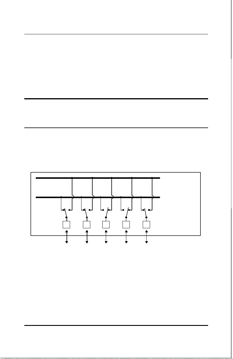
A dual-speed hub is actually two repeaters in one enclosure. The
10Mbps repeater receives Ethernet transmissions from any of its
ports, and retransmits them to all other ports operating at 10Mbps.
Similarly, the 100Mbps repeater retransmits Fast Ethernet transmissions from ports operating at 100Mbps to all other ports operating
at the same speed.
Introduction
Page 19
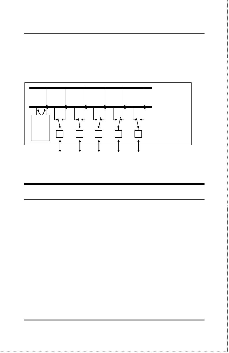
If there is a switch module, or a TE100-DS16X, TE100-DM16X,
TE100-DS24X or TE100-DM24X hub presents in the stack, then the
switch module serves as a bridge between the two indepen dent segments.
10Mbps Repeater
100Mbps Repeater
NWay Detection
TE100-DSM
Switch
Module
RJ-45 Ports
100Mbps
Ethernet
Station
100Mbps
Ethernet
Station
10Mbps
Ethernet
Station
10Mbps
Ethernet
Station
100Mbps
Ethernet
Station
100BASE-TX Technology Overview
100Mbps Fast Ethernet Introduction
Computers today have become increasingly powerful, with the capability to accommodate very sophisticated applications such as
multimedia applications, video-conferencing, and CAD/CAM. To utilize these technologically advanced applications more efficiently, there
is also a growing demand for faster networks that can handle heavy
network traffic.
Recognizing this need for greater bandwidth and lower latency, a
variety of technologies such as FDDI, ATM, and Fast Ethernet
(100Mbps) have been adopted by many vendors. Fast Ethernet tec hnology stands out as the most inexpensive and smoothest migration
Introduction 5
Page 20

Dual-Speed Stackable Hubs User’s Guide
path for existing 10Mbps Ethernet users in part because it doesn’t
require a protocol translation when sharing data with 10Mbps
Ethernet.
Fast Ethernet is a relatively new standard specified by the IEEE
802.3 LAN committee. It is an extension of the 10Mbps Ethernet
standard with the ability to transmit and receive data at 100Mbps,
while maintaining the CSMA/CD Ethernet protocol. Since Fast
Ethernet is compatible with all 10Mbps Ethernet environments, it
provides a straightforward upgrade without wasting the company’s
existing investment in hardware, software, and trained personnel.
Cables and Connectors
Category 5 unshielded twisted-pair (UTP) cables and shielded
twisted-pair (STP) cables are both supported. Category 5 UTP cable
uses the same RJ-45 connector used with 10BASE-T, wired in the
same configuration.
Topology
A Fast Ethernet workgroup is configured in a star topology and is
built around a maximum of two repeaters. Each workgroup forms a
separate LAN (also known as a segment or collision domain), and
these workgroups can be easily interconnected through switches,
bridges, or routers to form one LAN large enough to encompass a
high-rise building or campus environment. Recent innovations in
LAN hub technology such as stackable hubs, coupled with the decreasing cost of switches, bridges, and routers, allow the design of
low-cost, efficient Fast Ethernet workgroups and enterprise LANs.
The following factors strongly influence the architecture of Fast
Ethernet networks:
Introduction 6
Page 21

?? The EIA/TIA 568 Wiring Standard imposes a 100 meter limit
on horizontal runs of twisted-pair cables; that is, connections
from the wiring closet to the end-station.
?? Fast Ethernet’s increased operational speed reduces the
maximum distance between all elemen ts of the LAN (see below).
?? The EIA/TIA 568 Wiring Standard does not support the use of
coaxial cables for horizontal wiring.
Network Diameter
Network diameter, which is the distance between two end-stations in
the same collision domain, is the primary difference between traditional Ethernet and Fast Ethernet. Due to the increased speed in
Fast Ethernet and adherence to the EIA/TIA 568 wiring rules, the
network diameter of a Fast Ethernet collision domain is limited to
205 meters; in contrast, the maximum 10BASE-T Ethernet collision
domain diameter can be up to 500 meters.
Hub Types
Unlike 10BASE-T hubs which are all functionally identical, Fast
Ethernet hubs are divided into two distinct types: Class I and Class
II. A Class I hub repeats all incoming signals on one port to the
other ports by first translating them to digital signals and then retranslating them back to line signals. These translations are
necessary when connecting various network media to the same collision domain, such as when combining two wire-pair 100BASE-TX
media with four wire-pair 100BASE-T4 media. Only one Class I hub
can exist within the same collision domain, thus this type of hub
cannot be directly inter-linked. A Class II repeater, on the other
hand, immediately repeats all incoming line signals on one port to
the other ports; no translations are performed. This type of hub connects identical media within the same collision domain; for example,
Introduction 7
Page 22

Dual-Speed Stackable Hubs User’s Guide
TX to TX. At most, two Class II hubs can exist within the same collision domain.
As mentioned earlier, stackable Class II hubs can be used to increase
the number of available nodes in a collision domain. An entire hub
stack counts as a single repeater. TE100-DM/DS series hubs are
Class II devices.
Introduction 8
Page 23

2
2 U NPACKING AND
S ETUP
This chapter provides information on the unpacking and initial installation of your hub stack.
Unpacking
Open the shipping carton of your hub and carefully unpack the contents. The carton should contain the following items:
? ?One dual-speed stackable hub
? ?One AC power cord, suitable for your area’s electrical power
connections
? ?One daisy-chain cable
? ?Four rubber feet to be used for shock cushioning
? ?Six screws and two mounting brackets
? ?Management module diskette (master models only)
? ?This User’s Guide
Unpacking and Setup 9
Page 24
Dual-Speed Stackable Hubs User’s Guide
Inspect the hub and all accompanying items. If any item is damaged
or missing, report the problem to your dealer.
Identifying External Components
This section identifies all the major external components of the hub.
Both the front and the rear panels are shown, followed by a description of each panel feature. The indicator panel is described in detail
in the next chapter.
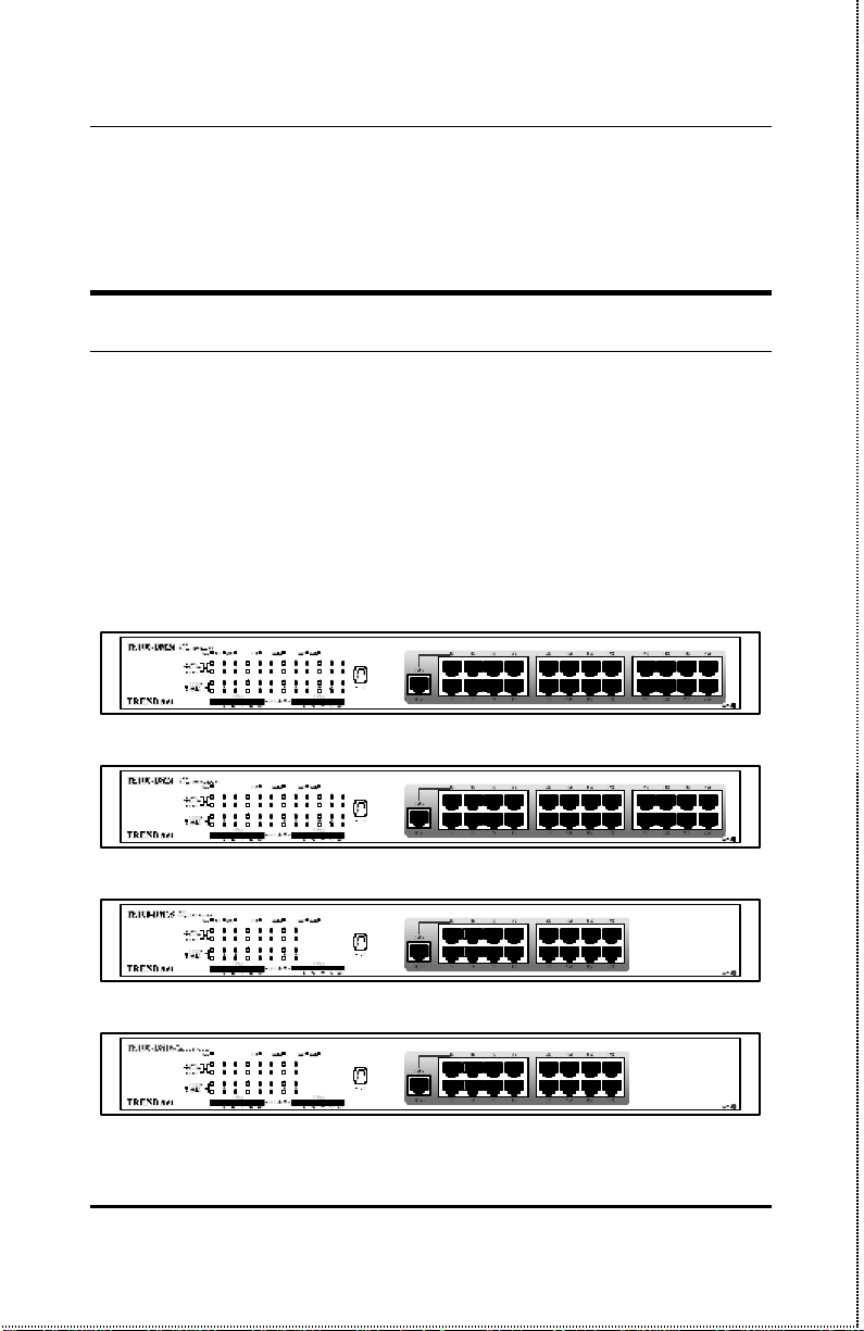
Front Panel
TE100-DM24 / TE100-DM24X Front Panel
TE100-DS24 / TE100-DS24X Front Panel
TE100-DM16 / TE100-DM16X Front Panel
TE100-DS16 / TE100-DS16X Front Panel
Unpacking and Setup 10
Page 25

? ?LED Indicator Panel
Refer to the next chapter, Understanding Indicators, for detailed
information about each of the hub’s LED indicators.
? ?Twisted-Pair Ports
Use any of these ports to connect stations to the hub. The ports
are MDI-X Nway ports, which means you can use ordinary
straight-through twisted-pair cable to connect the hub to PCs,
workstations, or servers through these ports, and the speed of the
connection will be detected automatically. If you need to connect
to another device with MDI-X ports such as another hub or an
Ethernet switch, you should use a crossover cable, or connect using the Uplink port (described below). For more information
about crossover connection, see the Crossover Cables section on
page 76.
? ?Uplink Port
The Up-link port is an MDI port, which means you can connect
the hub (or hub stack) to another device with MDI-X ports using
an ordinary straight-through cable, making a crossover cable unnecessary.
Port 1 and the Up-link port are the same logical port, except
their pin-outs are different. Do not use both Port 1 and the
Up-link port at the same time.
Unpacking and Setup 11
Page 26
Dual-Speed Stackable Hubs User’s Guide
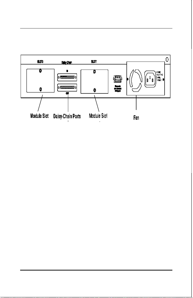
Rear Panel
(Note that the figure shows the rear panel for “Master” model.)
? ?Module Slots
Used to install module options for various kinds of additional con-
nections, as well as the switching 10Mbps/100Mbps bridge
module. (In the TE100-DS16X, TE100-DM16X, TE100-DS24X
and TE100-DM24X, module slot 1 is already occupied by the
“switch module” which is standard on these models.)
? ?Daisy-Chain IN Port
When cascading a set of stackable dual-speed hubs, this port
should be connected to the Daisy-Chain OUT port of the prev ious
hub in the stack (usually placed immediately above it). A cascade
of five hubs can be created in this way. The first and last hubs in
the stack use only one of the daisy-chain ports, while the others
use both.
? ?Daisy-Chain OUT Port
Works in conjunction with the Daisy-Chain IN Port (see above).
Connect this port to the Daisy-Chain IN Port of the next hub in
Unpacking and Setup 12
Page 27

the stack (usually placed immediately below it), using the enclosed daisy-chain cable.
? ?Diagnostic (Console) Port -- Master Models Only
This 9-pin serial connector is used for connecting a console to the
TE100-DM/DS series master hubs for out-of-band management of
this particular hub or the entire stack.
? ?Fan
Provides air circulation and heat dissipation. Be sure to leave
adequate space at the rear of the unit for proper ventilation.
? ?AC Power Connector
For the power cord.
Installing the Hub
Installation
The site where you install the hub stack may greatly affect its performance. When installing, consider the following pointers:
? ?Install the hub stack in a fairly cool and dry place. See Ap-
pendix D, Specifications, for the acceptable temperature and
humidity operating ranges.
? ?Install the hub stack in a site free from strong electromagnetic
field generators (such as motors), vibration, dust, and direct
exposure to sunlight.
Unpacking and Setup 13
Page 28
Dual-Speed Stackable Hubs User’s Guide
14
? ?Leave at least 10cm of space at the front and rear of the hub
for ventilation. For more information see, “Environmental and
Physical” on page 84.
? ?Install the hub on a sturdy, level surface that can support its
weight, or in an EIA standard-size equipment rack. For information on rack installation, see the next section, Rack
Mounting.
When installing the hub stack on a level surface, attach the rubber
feet to the bottom of each device. The rubber feet cushion the hub
and protect the hub case from scratching.
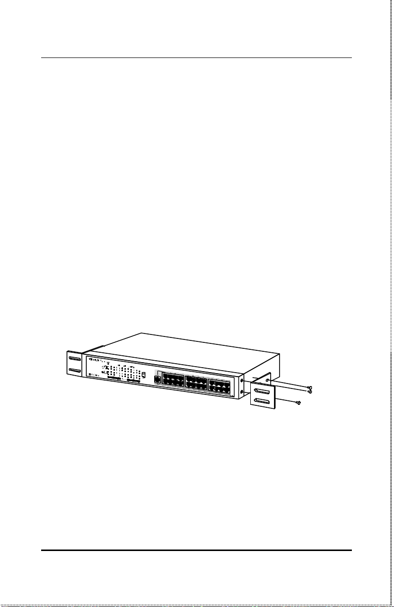
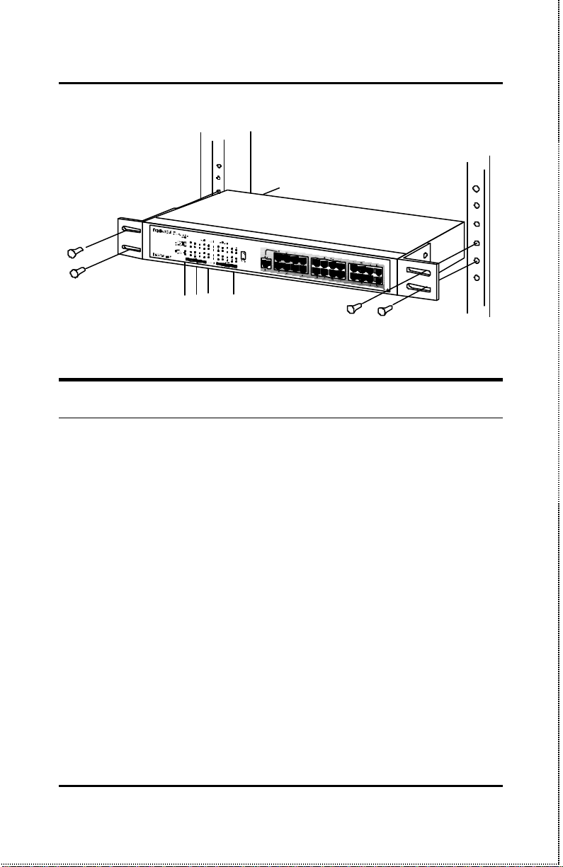
Rack Mounting
The hub can be mounted in an EIA standard-size, 19-inch rack,
which can be placed in a wiring closet with other equipment. Attach
the mounting brackets at the hub’s front panel (one on each side),
and secure them with the pr ovided screws.
Then, use screws provided with the equipment rack to mount each
hub in the rack.
Unpacking and Setup
Page 29
Replacing the Power Supply
The hub comes with a removable power supply for easy replacement.
In the unlikely event that the power supply fails or is damaged, follow the steps below to replace it:
1. Disconnect the power cord from the AC outlet.
2. Disconnect the power cord from its connector on the rear of the
hub.
3. Using a Phillips screwdriver, remove the screws securing the
power supply to release the unit.
4. Remove the power supply by sliding it out the rear of the chas-
sis. Do not plug in the power supply when it is outside the
chassis! Doing so could cause personal injury or damage to the
power supply.
Unpacking and Setup 15
Page 30

Dual-Speed Stackable Hubs User’s Guide
5. Slide the replacement power supply into the chassis, engaging
the connector carefully.
6. Attach the power cord to the connector of the power supply and
connect the other end of the power cord to the AC supply
source.
Unpacking and Setup 16
Page 31

3
3 U NDERSTANDING
INDICATORS
Before connecting network devices to the hub, take a few minutes to
look over this section and familiarize yourself with the front panel
LED indicators of your dual-speed hub, depicted below.
TE100-DM24 / TE100-DM24X Indicator Panel
TE100-DM16 / TE100-DM16X Indicator Panel
TE100-DS24 / TE100-DS24X Indicator Panel
Understanding Indicators 17
Page 32

Dual-Speed Stackable Hubs User’s Guide
TE100-DS16 / TE100-DS16X Indicator Panel
Hub State Indicators
? ?Power Indicator
This indicator lights green when the hub is receiving power ; oth-
erwise, it is off.
? ?Collision Indicators (COL10 and COL100)
These indicators indicate data collisions on the respective 10Mbps
Ethernet or 100Mbps Fast Ethernet segments of the hub. (If several hubs are stacked or linked together, all of them should detect
and indicate the same collision, since collisions span the entire
network segment.) Whenever a collision is detected, the respective COL indicator will briefly blink amber.
Understanding Indicators 18
Page 33

? ?Segment Utilization % (10Mbps and 100Mbps)
The utilization bar graphs provide a quick reference on the cur-
rent traffic load relative to the total available 10Mbps or 100Mbps
network bandwidth. The graphs display a measure of the percentage of bandwidth in use on the respective network segment.
All data packets are counted, whether valid or not.
? ?Hub ID Indicator
The Hub ID readout shows the ID (group) number of the hub
within the hub stack. The first time a hub is powered on within
a hub stack, the master hub in the stack assigns that hub an
available ID number which is then added to each hub’s factory serial number (encoded on an EEPROM memory chip). The hub ID
is then permanently assigned.
In an unmanaged stack (all slave models), all IDs will read “0”
and no permanent ID assignment is made. In a stack with a
master (intelligent) model, the master hub will detect the other
hubs in the stack and automatically assign ID numbers which
are then permanently saved by each hub.
Module Indicators (SLOT1 & 2)
The two module indicators, SLOT1 and SLOT2, indicate a good link
to a module installed in the respective slot. For the switch module
the indicator will come on when the module is installed. For other
modules, the slot link indicator should light whenev er the module is
installed and there is a valid link.
Understanding Indicators 19
Page 34

Dual-Speed Stackable Hubs User’s Guide
Port State Indicators
There is one port state indicator for each of the twisted-pair ports on
the hub. Each port? LED status indicator reports the port? link
and activity status, and shows whether or not the port has been partitioned.
The following describes each indicator and the meaning of each condition:
? ?Link (green)
The indicator of a port lights green when the port is connected to
a powered Ethernet or Fast Ethernet station. If the station to
which the hub is connected is powered off, or if there is a problem
with the link, the LED will remain off.
? ?Receive (blinking green)
When information is received on a port, its indicator will blink off
briefly. Upon reception, the data will be transmitted to all other
connected ports.
? ?Auto-partition (blinking amber)
The indicator of a port blinks amber when the port is automati-
cally partitioned due to an abnormal network condition.
The hub will temporarily partition a port when too many line er-
rors or too many collisions are detected on the port. While the
segment is automatically partitioned, the port will be isolated
from the rest of the network segment. When the problem is corrected or a valid data packet is received through the port, the port
is automatically reconnected.
? ?Disabled (steady amber)
Understanding Indicators 20
Page 35

The indicator of a port is orange when the port has been manually
disabled. No packet transmission or reception can occur on the
port.
If there is a TE100-DM16, TE100-DM16X, TE100-DM24, or
TE100-DM24X master hub in the stack, then ports can be manually disabled and enabled via the on -board console interface or via
an SNMP -based network management pr ogram. You can choose
to partition a port even when there is nothing wrong with it, for
example, to prevent a certain device from accessing the network.
SNMP Indicator
(Master models only.)
This indicator comes on when the SNMP agent of a TE100-DM/DS
series master hub is active. In a stack with both a Primary and a
Backup Master, the SNMP LED of the Primary master will be lit
and will flash to indicate SNMP activity. The SNMP LED of the
Backup Master will remain off at all times.
Port Speed Indicators
There is also a port speed indicator for each of the twisted-pair ports
on the hub. The port? speed indicator should light green when a
100BASE-TX device is connected to the port, it will remain dark if
the port is unconnected or if a 10BASE-T device is connected.
Understanding Indicators 21
Page 36

Dual-Speed Stackable Hubs User’s Guide
Console Port Indicator (CON)
(Master models only.)
This indicator lights continuously under the following two conditions:
1. A good connection has been established with a console (for example, a PC or other computer). The diagnostic port of a
TE100-DM/DS series master hub must be connected to the
console's RS-232 serial port using a normal serial cable.
OR
2. The console computer is on -line and connected to the on-board
console program either through terminal emulation or a
TELNET session.
Refer to Chapter 4, Making Connections, for directions on establishing a connection with the diagnostic port, and Chapter 5, Master
Hub Setup and Management, for information about how to use the
console interface.
Understanding Indicators 22
Page 37

4
4 MAKING C ONNECTIONS
This chapter discusses how to make connections to the hub’s?
twisted-pair ports and console port, cascading hubs to create a stack,
and linking with other hubs (or hub stacks).
Hub Cascading/Building a Stack
You can stack up to five hubs using the daisy-chain ports to form one
logical hub. In this configuration, the interconnected hubs constitute
a single logical unit, providing a maximum of 120 twisted-pair ports.
Use the provided daisy-chain cable to connect the Daisy-Chain OUT
port on the rear panel of one hub to the Daisy-Chain IN port on the
hub below it, as shown in the figure below. Repeat this pr ocedure for
each hub to be included in the stack.
Each time a new hub is added to the stack, all hub IDs will temporarily revert to 0, indicating a system reset. After the reset, the hub
IDs should return to their previous values.
Making Connections 23
Page 38

Dual-Speed Stackable Hubs User’s Guide
24
Hubs should not be added to the stack or removed from the stack
while the power is on at any hub in the stack.
Note: Always turns off power to the entire
stack before adding or removing hubs.
Making Connections
Page 39

Connectivity Rules
Ethernet (10Mbps) networks have the following connectivity rules:
? The maximum length of a twisted-pair cable segment is 100
meters. Cabling should be Category 3 or better (Category 5 for
100Base-TX connections).
? Between any two end-stations in a collision domain, there may
be up to five cable segments and four intermediate repeaters
(hubs, hub stacks, or other repeaters).
? If there is a path between any two end-stations containing five
segments and four repeaters, then at least two of the cable
segments must be point-to-point link segments (e.g., 10BASET or 10BASE-FL), while the remaining segments may be populated (mixing) segments (e.g., 10BASE-2 or 10BASE-5).
Fast Ethernet (100Mbps) networks have the following connectivity
rules:
? The maximum length of a twisted-pair segment (that is, the
distance between a port in the hub to a single-address network
device such as a PC, server, or Ethernet switch) is 100 meters.
Cabling and other wiring should be certified as Category 5
UTP or shielded twisted-pair (STP).
? The maximum diameter in a collision domain is about 205
meters using two Class II hubs (or hub stacks).
? Between any two end-stations in a collision domain, there may
be up to three cable segments and two Class II hubs or hub
stacks.
Making Connections 25
Page 40

Dual-Speed Stackable Hubs User’s Guide
The Diagnostic Port
The diagnostic port on the rear panel of the master hub is used to
establish a connection with a device to allow out-of-band management of the TE100-DM/DS series hubs stacked with it. The console
device connected to the diagnostic port can be a terminal (or a computer running terminal-emulating software) or a PC running
TCP/IP TELNET .
Diagnostic Port Connection
The diagnostic port is an RS-232 DCE interface. To establish a
physical line connection with an RS-232 serial port (DTE) on a PC
acting as a console, all you need is a straight serial cable, as shown
in below. Note that a DCE-to-DTE connection requires a straight
serial cable, not a null-modem cable.
You can use the diagnostic port on a TE100-DM/DS series master
hub to connect a VT100-compatible terminal or a computer running
an ordinary terminal emulation program (such as the Terminal Program included with the Windows operating system). In all cases,
your terminal parameters will need to be set to:
? VT-100/ANSI compatible,
? Arrow keys enabled,
? 9600 baud,
? 8 data bits,
? No parity,
? 1 stop bit.
Making Connections 26
Page 41

You can also access the same functions over a TELNET link. Once
you have set an IP address for your hub (see the beginning of this
chapter), you can use a TELNET program (in a VT -100 compatible
terminal mode) to access and control the hub. All of the screens are
for the most part identical, whether accessed from the diagnostic port
or from TELNET.
A console device can manage a TE100-DM/DS series master hub
operating in a stack master or stand-alone master role. Use the
on-board console program for out-of-band management or a SNMP
management software for in-band or out-of-band management.
A console device can only manage a TE100-DM/DS series hub if it
is cascaded to a TE100-DM/DS series master hub. Use either the
on-board console program or an SNMP-based network management program to manage the stack.
Hub to End-Station Connection
After installing the hub properly, it can support up to sixteen
(TE100-DS16, TE100-DS16X, TE100-DM16, TE100-DM16X) or
Making Connections 27
Page 42

Dual-Speed Stackable Hubs User’s Guide
twenty-four (TE100-DS24, TE100-DS24X, TE100-DM24, TE100DM24X) end-station connections. Fast Ethernet connections require
either a Category 5 UTP cable or a STP cable. These cables can be
up to 100 meters long.
Each Ethernet connection requires a Category 3 or better UTP cable.
It is recommended that you use Category 5 cabling for all connections. This makes it easier to upgrade all stations to 100Mbps.
You can connect any combination of PCs, servers, and other singleaddress network devices to the twisted-pair ports using straightthrough twisted-pair cables. These cables should not be crossed over.
The following figure illustrates the pin assignments for a straightthrough cable:
When connecting a PC or a server, the system being connected
should have an Ethernet or Fast Ethernet network interface card
with a twisted-pair port. The following figure shows a typical connection between the hub and end-stations:
Making Connections 28
Page 43

Hub-to-Hub Uplink
You can link two hubs or hub stacks to each other using any of the
twisted-pair ports or the Up-link port. Linking hubs using ordinary
twisted-pair ports requires crossover twisted-pair cables; linking using one ordinary twisted-pair port and the Up-link port requires an
ordinary straight-through twisted-pair cable. The Up-link port is
shared with Port 1, and you should not use both Port 1 and the Uplink port at the same time.
When connecting two hubs or hub stacks in this fashion, the maximum distance between any two end-stations in a collision domain is
205 meters. If each link between the hub and an end-station is 100
meters, then the hub-to-hub connection is limited to 5 meters. However, if the longest hub-to-end-station connection is less than 100
meters, then the hub-to-hub connection can be up to 100 meters as
long as 205-meter total network diameter rule is followed.
The following table describes different methods of linking hubs (or
hub stacks):
Making Connections 29
Page 44

Dual-Speed Stackable Hubs User’s Guide
HUB PORT
USED
Normal Switch or
Uplink Straight-Through (||)
Server (or PC) Straight-Through (||)
Uplink Switch or
Uplink Crossover (X)
Server (or PC) Crossover (X)
A crossover cable is a straight-through twisted-pair cable in which
the wires have been crossed. The figure below shows the pin assignments for an Ethernet or Fast Ethernet crossover cable:
DEVICE PORT
TYPE
Non-
Hub
Hub
Uplink
NonUplink
CABLE TO USE
Crossover (X)
Straight-Through (||)
NOTE: The first twisted-pair port (Port 1) is logically
shared with the Up-link port. If you connect
a hub to the Up-link port, then do not use
Port 1.
Making Connections 30
Page 45

Optional Module Connections
There are three optional modules that may be added to any of the
TE100-DM/DS series hubs. Each hub can accommodate two modules. Each of the modules offers a different additional network
interface that allows for greater flexibility in how these hubs may be
used in a network.
The sections that follow provide a brief overview of the module and
basic instructions on any settings and indicators.
Module Installation
The installation procedure for each module is the same. Additional
information about each module is provided below.
To install any of the modules:
1. Locate one of the module slots in the hub’s rear panel. (Note
that the TE100-DSM Switch Module can only be installed in Slot
1 – the center slot.)
2. Using a screwdriver, undo the two screws and remove the dust
cover on the module slot.
3. Holding the module component-side up and connector-side in,
gently slide the module along the guides and seat it in the internal connector.
4. Using a screwdriver, replace the two screws and tighten until
snug.
Making Connections 31
Page 46

Dual-Speed Stackable Hubs User’s Guide
We recommend that you retain the dust cover in case you need to
remove the module for an extended period sometime in the future.
Switch Module
The switch module is used to allow interconnection between the
10Mbps and 100Mbps segments in the hub or hub stack. Each hub
stack should have one switch module (such as the one included in the
TE100-DS16X, TE100-DM16X, TE100-DS24X or TE100-DM24X) to
allow 10Mbps and 100Mbps stations to intercommunicate. Note that
the switch module can only be installed in Slot 1 – the center slot.
Also the presence of switch modules and their operational status can
be viewed on the ”Network Monitoring – Bridge Information” screen.
NOTE: In a stack containing a TE100-DM16,
TE100-DM24, TE100-DM16X, or TE100DM24X intelligent master hub, more than
one switch module may be used to provide
increased reliability through redundancy.
The Spanning Tree Protocol implemented in
the management agent can control the
switch modules to provide link redundancy
and prevent network loops but only when
Making Connections 32
Page 47

multiple modules are installed in hubs on the
primary master segment.
Fiber Optic Module
The Fiber Optic module provides a standard Fast Ethernet
100BASE-FX fiber optic connector. A fiber optic connection of this
kind is particularly useful for creating a link between two TE100DM/DS series hub stacks, placing them in separate collision domains. A link of this sort eliminates the need for an external switch
to divide stacks into separate domains. Dividing the stacks into
separate collision domains overcomes the Fast Ethernet two-repeater
limitation, and effectively doubles overall bandwidth.
The Fiber Optic module includes the following LED indicators:
?? Power/Tx? this LED is lit when the hub is on and blinks when
the module is transmitting packets.
?? Link/Rx? this LED is lit when the fiber optic ports are properly
connected to a powered-on device and blinks when the module is
receiving packets.
?? Collision? this LED blinks when there are packet collisions on
the fiber optic link.
Making Connections 33
Page 48

Dual-Speed Stackable Hubs User’s Guide
34
?? FDX? this LED is lit when the fiber optic port is set for Full
Duplex transmit and receive. When the LED is off, the fiber optic port is in Half Duplex mode.
The duplex mode DIP switch allows you to set the fiber optic lines to
Full Duplex mode operation. Only the right-hand switch (number 2)
is active. Use it to set the duplex mode.
Fast Ethernet Module
The Fast Ethernet module provides one additional twisted-pair Fast
Ethernet connection. A twisted-pair connection of this kind is particularly useful for creating a link between two TE100-DM/DS series
hub stacks, placing them in separate collision domains. A link of this
sort eliminates the need for an external switch to divide stacks into
separate domains. Dividing the stacks into separate collision domains overcomes the Fast Ethernet two-repeater limitation, and
effectively doubles overall bandwidth.
The Fast Ethernet module uses a MDI-X connector (not a straight
MDI) and, therefore, a crossover cable must be used when connecting
the module to another module (and under most other circumstances).
See Appendix A for pin-out information.
The Fast Ethernet module includes the following LED indicators:
?? Power/Tx? this LED is lit when the hub is on and blinks when
the module is transmitting packets.
?? Link/Rx? this LED is lit when the port is properly connected to
a powered-on device and blinks when the module is receiving
packets.
Making Connections
Page 49

?? Collision? this LED blinks when there are packet collisions on
the module line.
?? FDX ? this LED is lit when the port is set for Full Duplex
transmit and receive. When the LED is off, the port is in Half
Duplex mode.
NOTE: Because the Fast Ethernet module? port is
a NWay UTP port, once the hub is powered
on, it will automatically detect the duplex and
speed modes of any device connected to it.
The DIP switch may then be set to force the
duplex mode into a particular state. After the
DIP switch is set, the module will only operate at 100Mbps in the duplex mode selected.
The duplex mode DIP switch allows you to set the port to Full Duplex mode operation. Only the right-hand switch (number 2) is
active. Use the DIP switch to set the duplex mode.
Making Connections 35
Page 50

Page 51

5
5 MASTER H UB SETUP
AND MANAGEMENT
The TE100-DM16, TE100-DM16X, TE100-DM24, and TE100DM24X master hubs (hereafter and elsewhere referred to as
“SNMP master hubs”) provide an on -board console program that
allows you to set up and control all TE100-DM/DS hubs stacked
with it. This program can be accessed either with an ordinary
terminal (or terminal emulator) or over the network using the
TCP/IP TELNET protocol. You can use this program to perform
many basic network management functions.
The console program also allows you to prepare the hub for management using an SNMP-based network management system.
This chapter describes how to use the console pr ogram to access
the hub, change its settings, and monitor its operation.
Note that if you want to manage the hub in-band you need to follow the instructions in the first section of this chapter (below) to
prepare the hub for in-band management. If you need information about connecting a console device to the diagnostic port for
out-of-band management, see the relevant sections of Chapter 4.
Master Hub Setup and Management 37
Page 52

Dual-Speed Stackable Hubs User’s Guide
Navigation and Co nventions
This section describes how to navigate the master hub management software and the conventions used in that software.
Navigation
The Tab keys move the cursor from field to field. Note that they
are uni-directional (i.e., Shift+Tab is not a functional combination). Up and Down arrow keys allow cursor movement between
some fields.
The Spacebar is a toggle switch for all variables that can be
changed but wherein possible values are preset.
The Delete and Backspace keys remove entered text as in most
software packages.
Pressing Ctrl-r refreshes the current screen.
Screen Conventions
A colon(“:”) precedes fields that cannot be changed.
Toggle changed fields are surrounded by angle brackets <>.
Variables with values that must be keyed-in are surrounded by
square brackets [].
Uppercase letters are reserved for command items such as SAVE
or LOGOFF. Highlighting the item and pressing Enter activates
the command.
Note: Both the navigation and screen conven-
tions information can be obtained under
HELP in the system management software.
Master Hub Setup and Management 38
Page 53

In-Band Setup Instructions
This section describes how to setup the hub for in-band management.
Getting Started
Physically install and cascade the hubs and power on the hub
stack according to the directions in other parts of this manual. At
this point, the hub stack is ready for use as an ordinary
unmanaged repeater.
The master hubs in the series come without IP addresses assigned (IP = 0.0.0.0). Without a valid IP address, the master hub
will show a POST error indication and repeatedly restart itself
once every minute or so. If you want to manage your hub using a
network management system, you will have to assign an IP address to the hub. There are two different ways to configure the
hub with a new address, as described below.
Assigning an IP Address Using BOOTP
If your Fast Ethernet network has a BOOTP (BOOTstrap Protocol) server, you can add the hub’s Ethernet (MAC) address (which
is printed on a sticker on the bottom of the hub, or you can obtain
it using the master hub console interface), IP address, subnet
mask, and boot filename to your BOOTP server’s configuration
tables. The boot filename field of the hub’s BOOTP configuration
should contain the filename of a TE100-DM/DS series master hub
boot configuration file accessible on your local TFTP (Trivial File
Transfer Protocol) server. This file can be empty. For more detailed information about the boot configuration file contents, see
Appendix C : Boot Configuration File of this manual.
Assigning an IP Address Using the Diagnostic Port
To assign an IP address manually,
Master Hub Setup and Management 39
Page 54

Dual-Speed Stackable Hubs User’s Guide
1. Connect a VT -100 compatible terminal or a personal com-
puter running a VT-100 compatible terminal emulation
program to the DB-9 console port at the rear of the master
hub. The cable should be an ordinary RS-232C cable. The
terminal communications parameters should be set to
9600bps, 8 bits, no parity, and 1 stop bit.
2. As the hub begins its boot process, hit Control-C to enter
the PROM System Menu.
3. Choose TCP/IP Parameters Configuration, and enter a
valid IP address, network mask, and (optional) gateway
router IP address. Choose SAVE and press <Enter> to let
the changes take effect, and then choose EXIT.
4. If you will not be using TFTP to download a hub configura-
tion file, choose Software Update and toggle the Software
Update Control to “Disable” using the Space Bar. Again,
choose SAVE and then EXIT.
5. Choose Execute Bootstrap to restart the hub.
You are now ready to use your TE100-DM/DS series hub stack,
and to manage it from a network management station on your
network. See the Stack Management User’s Guide for more information about how to manage the stack using a network
management pr ogram.
Backup Master Function
Within a TE100-DM/DS series hub stack, in addition to a master
hub for management purposes, a standby backup master can also
be installed. If a hub stack has two master units, the first powered-on Master unit or the unit that is higher in the stack will
Master Hub Setup and Management 40
Page 55

manage the stack and be designated as the ”Primary Master.”
Master hubs in the series include a built-in contention algorithm
which determines which hub will manage the stack and which
will operate in standby mode. If, during power -on, the two master
hubs in the stack both attempt to initialize as the Primary Master, this collision will result in an automatic stack reset indicated
by all hub ID numbers changing to 0 temporarily. If the current
Primary Master Hub fails or loses power, the standby master will
take over and manage the hub stack.
Segmenting Hubs
Switching hub technology has made it more common to segment
local area networks into smaller pieces to reduce congestion.
Segmenting makes it easier to balance network loads, since fewer
users are sharing the available bandwidth.
A hub stack makes network management convenient, but too
many stations on a single network segment may give slow response at peak network loads. Therefore, this hub series provides
a way to segment hubs from the stack into their own collision
domains. Segmenting hubs can be accomplished with a simple
management command and does not require any hardware or wiring changes.
Though the hubs continue to be cascaded together and are managed as a single unit, each hub can either be a part of the collision
domain of the rest of the stack, or can be separated into its own
network segment. These separate segments can be bridged by
connecting them through a compatible switching hub.
Master Hub Setup and Management 41
Page 56

Dual-Speed Stackable Hubs User’s Guide
The figure above shows an unsegmented hub stack. All hubs in
the stack are in the same collision domain because they are connected together through the daisy-chain ports.
The figure below shows a stack of hubs that is divided into three
separate collision domains. Hub three and four are isolated from
the main segment (collision domain one) using the hub's segmentation capability, putting them into their own isolated collision
domains two and three respectively. A switch, bridge or router
can be used to connect the three collision domains so that traffic
can pass between them, yet keeping them isolated to reduce congestion on each segment.
For information about segmenting hubs using the network management module for the hub, see the ”Hub Stack Management:
Controlling Hubs in the Hub Stack” section later in this chapter.
Master Hub Setup and Management 42
Page 57

NOTE: Hub Segmentation is controlled by the
master hub. When the master hub completes its initialization, it will restore any
prior segmentation of the hubs. Therefore, if you are using a switch or bridge to
join different segments, be sure to enable
the IEEE 803.1d Spanning Tree Protocol
to prevent temporary network loops
Logging in to the Hub Console
The TE100-DM/DS series master hubs support user-based security that allows you to prevent unauthorized users from accessing
the hub or changing its settings. This means that before you can
access the functions of the hub, you will need to first log into the
hub, providing a password. This section tells how to log onto the
hub, and how to change your password.
Logging In
When you first connect to the hub, it will display the login screen:
Master Hub Setup and Management 43
Page 58

Dual-Speed Stackable Hubs User’s Guide
44
To log in, complete these steps:
1. Type in your user name and press <Enter>.
2. Type in your password and press <Enter>.
3. With the cursor on the OK selection, press <Enter>.
NOTE: When the hub is shipped, the default user
name is TREND, and the default password is also TREND. You will need to use
this user name and password when you
first set up your hub or if you use the Factory Reset NVRAM to Default Value
menu selection. Change this user name
and password to protect the security
of your hub.
There are two levels of user privilege: Super User and General
User. The default user (TREND) has Super User privileges.
Some functions available to Super Users are not available to General Users. The main menu below is the menu for Super Users:
Master Hub Setup and Management
Page 59

Changing Your Password
To change your user password, follow these steps:
1. Choose User Account Change from the main menu.
2. Select Change Password. The following screen will be
displayed:
Master Hub Setup and Management 45
Page 60

Dual-Speed Stackable Hubs User’s Guide
Type in your user name and press <Enter>.
3. Type in your old password and press <Enter>.
4. Type in the new password you have chosen, and press <En-
ter>. Type in the same new password again in the next
blank space to verify what you typed.
5. Choose SAVE to put the new password into effect.
6. Choose EXIT to exit this screen.
This method can also be used by a Super User to change another
user’s password.
Master Hub Setup and Management 46
Page 61

Setting Up the Master Hub
This section describes how to set the hub’s console parameters for
various management options it supports. Note that the hub can
be managed in-band or out-of-band, and either through the builtin console program , or using an SNMP-management program.
TCP/IP Settings
The hub needs to have an IP address assigned to it so that the
network management system or TELNET client can communicate with it over the network. The TCP/IP Parameters
Configuration Menu allows you to change the settings for the two
different interfaces used by the hub: the internal Fast Ethernet
interface used for in-band communication, and the SLIP interface
used through the diagnostic port for out-of-band communication.
Note: if you need to set an IP address so that you can access the
hub console through a network, please see the first section of this
chapter.
Saved changes to any of the fields on this menu take effect the
next time the system is restarted. Fields that can be set include:
? ?Interface. This parameter displays the type of interface the
hub will use for management communications.
? IP Address. This parameter determines the IP address
used by the hub for receiving SNMP and TELNET messages. The address should be of the form xxx.xxx.xxx.xxx,
where each xxx is a number (represented in decimal) between 0 and 255. This address should be a unique address
on the network assigned to you by a network administrator.
The same IP address is shared by both the SLIP and
Ethernet network interfaces.
Master Hub Setup and Management 47
Page 62

Dual-Speed Stackable Hubs User’s Guide
? Subnet Mask. This parameter sets the subnet mask that
determines the level of the subnet that the hub is on. It
should be of the form xxx.xxx.xxx.xxx, where each xxx is a
number (represented in decimal) between 0 and 255. If no
subnetting is being done, the value should be 255.0.0.0 for a
Class A network, 255.255.0.0 for a Class B network, and
255.255.255.0 for a Class C network.
? Default Gateway. This parameter specifies the IP ad-
dress for a gateway or a router where frames with
destinations outside the current subnet should be sent. If
your network is not part of an inter -network, or you do not
want the hub to be accessible outside your local network,
you can leave this field blank.
? Send BOOTP Request upon Power Up. This parame-
ter determines whether or not the hub should send out a
BOOTP request when it is powered up. The BOOTP pr otocol allows IP addresses, network masks, and default
gateways to be assigned from a central BOOTP server; if
this option is set to “Yes”, the hub will first look for a
BOOTP server to provide it with this information before using local settings.
Master Hub Setup and Management 48
Page 63

The default setting for all TCP/IP variables is 0.0.0.0.
Out-of-Band Management and Console
Settings
You can use the Out-of-Band/Console Setting menu to choose
whether to use the hub’s RS-232 serial port for console management or for out-of-band TCP/IP communication using SLIP , and
to set the baud rate used for SLIP communications.
The following fields can be set:
? System Restart Out-of-Band Baud Rate. This pa-
rameter determines the serial port baud rate that will be
used the next time the hub is restarted. It applies only
when the serial port is being used for out-of-band (SLIP)
management; it does not apply when the port is used as a
console port. Available speeds are 1200, 2400, 9600, and
19200 bits per second.
Master Hub Setup and Management 49
Page 64

Dual-Speed Stackable Hubs User’s Guide
? Out-of-Band Dial-Up Phone Number . This information
is stored as a reference for the benefit of the system manager and does not cause the hub to dial out.
? System Restart Serial Port Setting. This parameter
determines whether the serial port should be used for out-ofband (SLIP ) management or for console management, starting from the next time the hub is restarted. It can be set to
either “Console” or “Out-of-Band.”
Software Update on Boot
The hub is capable of obtaining its boot-time configuration information, as well as updated versions of its internal firmware,
using TFTP (the Trivial File Transfer Protocol) and BOOTP (the
BOOT strap Protocol). You can use the Software Update menu to
control this feature.
The fields you can set on this menu are:
Master Hub Setup and Management 50
Page 65

? Software Update. This parameter determines whether or
not the hub will try to look for the configuration file over the
network. If set to Disable, the parameters below become irrelevant.
? Software Update Mode. This variable can be set to ei-
ther Network or Out-of-band. Determines whether the
configuration file should be obtained through the Ethernet
network or through the console port.
? Boot Protocol. This parameter can be set to either TFTP
ONLY or BOOTP & TFTP. Applies only if the S/W Update
control is enabled.
? Boot Server IP Address. This variable is the IP address
of the TFTP server where the configuration file is located.
This entry is used only if the S/W Update Control is en-
abled and your boot protocol is TFTP only ; if you are using
BOOTP&TFTP mode, or if Send BOOTP Request on Power
Up is enabled, the address will be obtained from the
BOOTP server.
? Boot File Name. The pathname of the configuration file
on your TFTP server. Normally, this is the pathname of
the .CFG file on your hard disk. This entry is used only if
your boot protocol is TFTP ONLY; if you are using BOOTP
& TFTP mode, or if Use BOOTP to get IP after start up is
enabled, the pathname will be obtained from the BOOTP
server. For more information about the TE100-DM/DS Series Master Hub configuration file, please see Appendix C,
Boot Configuration File.
Master Hub Setup and Management 51
Page 66

Dual-Speed Stackable Hubs User’s Guide
SNMP Information
The System Configuration Menu screen shows a variety of information about your hub, and allows you to set the System Name,
System Location, and System Contact. These settings can be retrieved from the hub using SNMP requests, allowing them to be
used for network management purposes. Each of these fields is
restricted to 64 characters:
? System Name. This parameter corresponds to the MIB-II
object sysName, and is used to assign a name to the hub for
administrative purposes. The hub’s domain name is often
used, provided a name has been assigned.
? System Location. This parameter corresponds to the
MIB-II object sysLocation, and is used to indicate the physical location of the hub for administrative pu rposes.
? System Contact. This parameter corresponds to the
MIB-II object sysContact, and is used to note the name and
Master Hub Setup and Management 52
Page 67

contact information of the person responsible for administering the hub.
? Display Timeout. An additional setting, the console
time-out, may be used to automatically log out the console
interface after a predetermined period of inactivity. This
feature increases hub security by preventing access to the
hub after the interface has been inadvertently left logged
on. A setting of 0 disables this feature.
SNMP Traps
The hub sends out SNMP traps to network management stations
whenever certain exceptional events occur, such as when the hub
is powered on or when an SNMP request is made using an unknown community name. An SNMP trap sent to another
network management site provides a warning about, for example,
an attempted unauthorized access to the network or hub, or
changes to a network hub’s configuration that may effect other
Master Hub Setup and Management 53
Page 68

Dual-Speed Stackable Hubs User’s Guide
54
parts of the network. Traps are sent only to selected network
management hosts. The hub allows up to four different hosts to
receive traps from the system.
The following trap parameters can be set:
? IP Address. This parameter specifies the IP address of the
network management station which will receive traps from the
hub.
? SNMP Community String. This parameter specifies
the SNMP community name to be included in the trap request.
? Status. This determines whether this trap entry is valid
or invalid. You can delete an entry by changing its status
to Invalid.
Master Hub Setup and Management
Page 69

SNMP Security (Community Names)
SNMP (version 1) implements a rudimentary form of security by
requiring that each request includes a community name. A
community name is an arbitrary string of characters used as a
”Password” to control access to the hub. If the hub receives a request with a community name it does not recognize, it will trigger
an authentication trap, provided this feature has not been disabled.
The TE100-DM/DS series master hubs allow up to four different
community names to be defined, and the access rights for each
community can be separately set to either read only or read/write.
The status for each string can be toggled to either valid or invalid.
The community names public and private are defined by default;
you can change these names in addition to adding others. You
will need to coordinate these names with the community name
settings you use in your network management system.
Master Hub Setup and Management 55
Page 70

Dual-Speed Stackable Hubs User’s Guide
Adding and Deleting Users
Access to the console program, whether using the diagnostic port
or TELNET, is controlled by user names and passwords. Up to
three user names can be defined. One user, named TREND, is
defined by default; this user name can be removed if desired.
However, the console program will not let you delete the currently
logged-in user to prevent you from accidentally deleting all users
with Super User privileges – making it impossible to change important hub settings.
Only users with Super User privileges can add and delete users.
Add a User
To add a new user, perform these steps:
1. Choose User Account Change from the main menu. The
following screen will appear:
Master Hub Setup and Management 56
Page 71

2. Choose Create New User fr om the User Account Change
menu.
3. Enter the new user name, and assign an initial password.
Determine whether the new user should have Super User
or General User privileges.
4. Choose SAVE and press <Enter> to let the user addition
take effect.
5. Choose EXIT to leave the Create New User menu.
Delete a User
To delete a user, follow these steps:
1. Choose User Account Change from the main menu.
2. Choose Change Access/Delete Users from the User Ac-
count Change menu.
Master Hub Setup and Management 57
Page 72

Dual-Speed Stackable Hubs User’s Guide
3. Toggle the Status field of the user you wish to remove to
N/A. (To temporarily restrict a user’s access to the hub
console, you can toggle that user’s Status to Inactive.)
4. Choose SAVE and press <Enter> to let the user deletion
take effect.
5. Choose EXIT to leave the Delete Users menu.
Primary/Backup Master
The Primary/Backup Master Hub screen, accessible from the
Network Monitoring menu, is used to display the stack management status of each master hub in the stack. Fields in this
screen are for information only and cannot be changed. The
group ID, primary/backup status, IP address, and MAC address
for master hubs in the stack are displayed.
Master Hub Setup and Management 58
Page 73

Hub Stack Management
Several important hub parameters useful in the day-to-day management of the hub can be viewed and controlled using the Group
Configuration and Port State menus.
Controlling Hubs in the Hub Stack
The Group Configuration Menu screen, found under the Network
Monitoring menu, displays information about each of the hubs in
the stack.
Note: In this context, “Group” means “Hub.”
Master Hub Setup and Management 59
Page 74

Dual-Speed Stackable Hubs User’s Guide
The items displayed on this screen are:
? Group ID . This field indicates which hub is being dis-
played.
? Group Serial Number. Displays the hub’s factory
assigned serial number.
? Group Position Number. Displays the hub’s stack
position relative to the other hubs (1 is the highest in the
stack, 5 the lowest).
? Group Description. This field gives a description of the
given hub, showing its model number .
? Group Role. Shows what role the hub is currently play-
ing in the hub stack (primary master , standby master, or
slave).
? Group Port Capacity. This field shows the total num
ber of network ports on the hub.
Note: When modules with additional ports are
installed in TE100-DM/DS series hubs,
the Port Capacity number will
automatically adjust to reflect the added
ports. The management software does
not discriminate, any type of added or
removed port will change the Port
Capacity number.
? Group Hardware Revision. This field shows the de-
signed version of the hub hardware.
? Group Master Revision. Displays the designed version
for master hubs.
Master Hub Setup and Management 60
Page 75

? Group Status. This field shows whether the hub is up-
and-running or down.
? Group Last Oper Change. This field shows the time
when the hub was last added to or removed from the stack.
The format is hh:mm:ss.xx, with hh representing hours
since the master hub was turned on, mm the minutes, ss
the seconds, and xx representing 100ths of a second.
? Group Slot (1). Shows the status of module slot 1. If
there is a module installed in slot 1, this field will display:
MII, TP, FX, or Switch as determined by the type of module
installed. If there is no module installed, the field will display ”None.”
? Group Slot (2). Shows the status of module slot 2. If
there is a module installed in slot 2, this field will display:
MII, TP, FX, or Switch as determined by the type of module
installed. If there is no module installed, the field will display “None.”
? Group Isolate. Provides control of the hub’s current
network connection status and allows the system manager
to manually isolate a particular hub as needed and reconnect it later. Toggling the field to ”Isolate” separates the
hub’s data connection from the other hubs. Toggling the
field to ”Reconnect” re-establishes the connection. See
”Segmenting Hubs” earlier in this chapter for more information.
Master Hub Setup and Management 61
Page 76

Dual-Speed Stackable Hubs User’s Guide
You can use PREV GROUP and NEXT GROUP to display information about another hub, or you can enter the hub’s? Group
ID number directly in the Group ID field.
Controlling Individual Ports
The Port State Menu, accessible from the Network Monitoring
menu, allows you to view the status of individual ports and control their settings. The information displayed includes:
? Group ID. This field determines which hub’s ports are
displayed.
? Port ID . This field determines which port is displayed.
? Connector Type. This field shows the port connector
type.
Master Hub Setup and Management 62
Page 77

? Link Test. This field displays “Up” if there is a station
connected to the port; otherwise, it displays “Down”.
? Link Test State. This field displays “Enable” if the port
link status is to be auto-detected and displayed, otherwise it
displays “Disable”. This variable is user configurable.
? Receive Polarity. This field always displays “Normal” if
the hub is operating properly.
? Auto Partition. This field displays “Yes” if the port has
been automatically partitioned off from the rest of the network due to excessive errors on the segment. The field
displays “No” for normal oper ation.
? Admin State. This toggle determines whether the port
should be enabled or disabled (manually partitioned). Setting the Admin State to “Disabled” will isolate the port from
the rest of the network. This variable is user configurable.
? Port Speed. This field displays the port current operating
speed (100M or 10M) relative to the speed of the device connected to it.
? Speed Capability. This field displays the port current
speed setting, “Auto” for auto-detect/correct, “100M” for
100Mbps connections only, or “10M” for 10Mbps connections
only. This variable is user configurable.
Master Hub Setup and Management 63
Page 78

Dual-Speed Stackable Hubs User’s Guide
64
You can use PREV GROUP and NEXT GROUP to switch to
another hub, or PREV PORT and NEXT PORT to switch to an-
other port. You can also enter the port Group ID a Port ID
numbers to go directly to a different port.
Monitoring the Hub Stack
The hub supports several monitoring functions, allowing you to
keep statistics on the operation of each port, each hub, and the
entire network segment, as well as to monitor the addresses of the
packets received at each port.
Displaying Port and Group Statistics
The hub stack collects network transmission statistics for each
port, and each hub (group) in the stack. Statistics collected for
segments are tabulated differently and are explained in the next
section. You can choose which to view from the Statistics menu,
accessible under the Network Monitoring menu.
Master Hub Setup and Management
Page 79

The data categories provided for both port and group statistics are
the same. They are:
? Frames Too Long. This statistic counts frames longer
than the 1518-byte (octet) limit set by the Ethernet standard. This problem is likely caused by software errors.
? Very Long Events. This statistic counts events where a
signal is received that is longer than the jabber lockup pr otection timer setting. A high count in this field may
indicate noise on the line or a bad Ethernet interface.
? Short Events. This statistic counts events where less
than 10 bytes are received and the frame start delimiter is
invalid, or where the start frame delimiter is valid but less
than 2 bytes are received. This type of error may indicate
noise on the line.
? Late Events. This statistic counts collisions that occurred
at or after the 64th byte (octet) in the frame. A high count
here may indicate that delays on your Ethernet are too
long, and you have either exceeded the repeater count or cable length specified in the Fast Ethernet standard.
? Runt Frames . This statistic counts frames shorter than
the 64-byte (octet) minimum defined by the Fast Ethernet
standard. Runts are often caused by collisions.
? Collisions. This statistic counts collisions on the Ethernet
segment.
Master Hub Setup and Management 65
Page 80

Dual-Speed Stackable Hubs User’s Guide
? FCS Er rors. This statistic counts otherwise valid frames
that fail the CRC check.
? Alignment Errors. This statistic counts otherwise valid
frames that did not end on a byte (octet) boundary.
? Readable Frames . This statistic counts valid frames.
? Multicast. This statistic counts the number of good mul-
ticast packets received. Multicast events are messages sent
from one node to multiple nodes on the segment.
? Broadcast. This statistic counts the number of good
broadcast packets received. Broadcast events are messages
sent to all nodes on the segment.
? Auto Partitions. This statistic counts events where the
port was partitioned off from the rest of the network due to
excessive collisions or cabling problems.
? DRM (Data Rate Mismatch). This statistic counts
events where there is a frequency mismatch between the
received signal and the hub’s internal clock. A high count
in this field may indicate a hardware problem in the hub or
in an Ethernet interface.
? SA Changes. This statistic counts the number of times
the source address has changed.
? Isolates (only for 100Mbps connections). Counts the
number of times a port auto isolates.
? Symbol Error (only for 100Mbps connections). Counts
the number of times a received packet contained symbol errors. Only one symbol error is counted per packet
regardless of the number of symbol errors within the
packet.
Master Hub Setup and Management 66
Page 81

? Total Errors. This statistic is the sum of the FCS Error,
Alignment Error, Too Long Frame, Short Event, Late
Event, Very Long Event, and Data Rate Mismatch counters.
? Readable Octs. This statistic counts the total number of
bytes (octets) included in valid (readable) frames.
You can use PREV GROUP, NEXT GROUP, PREV PORT,
and NEXT PORT to switch hubs or ports. CLEAR COUNTER
resets all counters back to zero.
NOTE: The CLEAR COUNTER action only re-
sets the counters for the statistics
display; the underlying counters (i.e., MIB
variables) are not cleared.
Master Hub Setup and Management 67
Page 82

Dual-Speed Stackable Hubs User’s Guide
Displaying Segment Statistics
The hub stack collects network transmission statistics for each
segment in the stack. You can choose to view them from the Statistics menu, accessible under the Network Monitoring menu.
? StatsPkts. This statistic displays the number of packets
received from the network, including error packets.
? BroadcastPkts. This statistics counts the number of
good broadcast packets received on the segment.
? MulticastPkts. This statistics counts the number of good
multicast packets received on the segment.
? CRCAlignErrors. This statistic counts the number of
valid length packets (64 to 1518 bytes) that had a bad
Frame Check Sequence (FCS).
? UndersizePkts. This statistic counts the number of well-
formed packets that were smaller than 64 octets.
? OversizePkts. This statistic counts the number of well-
formed packets that were longer than 1518 octets.
? Fragments. This statistic counts the number of ill-
formed packets less than 64 octets and all events without a
start-of-frame delimiter regardless of their length.
? Jabbers. This statistic counts the number of jabber
events on the segment.
Master Hub Setup and Management 68
Page 83

? Collisions. This statistic counts the number of collisions
on the segment.
? 64 Octs. This statistic displays the number of packets
(both good and bad) that were 64 octets long.
? 65-127 Octs. This statistic displays the number of packets
(both good and bad) that were 65 - 127 octets long.
? 128-255 Octs. This statistic displays the number of pack-
ets (both good and bad) that were 128 - 255 octets long.
? 256-511 Octs. This statistic displays the number of pack-
ets (both good and bad) that were 256 - 511 octets long.
? 512-1023 Octs. This statistic displays the number of
packets (both good and bad) that were 512 - 1023 octets
long.
? 1024-1518 Octs. This statistic displays the number of
packets (both good and bad) that were 1024 - 1518 octets
long.
Master Hub Setup and Management 69
Page 84

Dual-Speed Stackable Hubs User’s Guide
? StatsOctets. This statistic displays the number of data
octets including those in bad packets and octets in FCS
fields but does not include preamble or other framing bits.
? Total Octs. This statistic displays the total number of
octets contained in valid frames received on this segment.
Node Tracking
The Node Tracking screen displays the origination MAC addresses of packets received by each node connected to the hub for
the last 12 receives.
Master Hub Setup and Management 70
Page 85

Group and port can be selected by entering the appropriate number(s) in the Group ID and Port ID fields or using the navigation
commands at the bottom of the screen.
Per-Port Intrusion Security
Each port on this hub can have intrusion security enabled. Intrusion security preven ts unauthorized individuals from accessing
the network. Through the network management software,
Ethernet addresses that represent authorized users can be assigned to each hub port. If a port receives a packet using a source
address other than those used by authorized users, the port is disabled and the network manager is notified.
Bridge Information
The bridge information screen allows the network administrator
to view the install and operation status of all bridging modules
within a segment. To avoid non -terminating network data loops,
Master Hub Setup and Management 71
Page 86

Dual-Speed Stackable Hubs User’s Guide
only one bridging module at a time can be active. The hub stack
management software always enables the module installed in the
highest hub in the stack. The management program can only
test for the presence or absence of an installed bridge and not
whether it is functional. Under the Bridge Present column, “N/A”
indicates no bridging module pr esent in that hub.
Resetting the Hub
You can use the console program to reset the hub stack, either
doing a system reset (which restarts the hubs and is identical to
powering them off and back on again) or a factory reset (which
resets the master hub, reverts all of its parameters back to their
factory default values, and restarts the entire hub stack).
Important Note: If it is necessary for you to
power-off the hub (or hub stack)
Master Hub Setup and Management 72
Page 87

and then restart it instead of using the reset functions, the hub
MUST BE POWERED-OFF for
a MINIMUM of TEN SECONDS.
If the hub stack has a backup master, the time required to complete the reset process will be longer than without one. Generally,
a stack reset should be complete within about two minutes.
System Reset
To perform a system reset, follow these steps:
1. Choose System Reset from the main menu. The following
confirmation message will appear:
Master Hub Setup and Management 73
Page 88

Dual-Speed Stackable Hubs User’s Guide
74
2. Move the cursor to Yes to confirm the reset and press <En-
ter>. After a few seconds delay, the hub should restart.
Factory Reset
Before performing a factory reset, be absolutely certain that this
is what you want to do. Once the reset is done, all of the master
hub’s stored settings (including TCP/IP parameters, SNMP parameters, the enabled/disabled settings of ports, etc.) will be
erased and restored to their factory default settings.
1. Choose Factory Reset NVRAM to Default Value from
the main menu. A confirmation message similar to that for
the System Reset will appear.
2. Move the cursor to Yes to confirm the reset and press <En-
ter>. After a few sec onds delay, the hub should restart,
and all of its parameters will revert to their default values.
Note: Doing a factory reset to the Primary Mas-
ter also resets the Backup Master
variables except for the Backup Master
IP address.
Master Hub Setup and Management
Page 89

A
6 C ABLES AND
C ONNECTORS
100BASE-TX Ethernet Cable and
Connectors
? Cable characteristics: 0.4 to 0.6 mm (22 to 26 AWG) 4- pair
(only two pairs/four wires are used for 100BASE-TX); Category
5 unshielded twisted-pair or EIA/TIA-568 compliant, 100-ohm
shielded twisted-pair
? Maximum segment length: 100 meters
? Maximum network diameter: 205 meters
? Connectors: RJ-45
Cables and Connectors 75
Page 90

Dual-Speed Stackable Hubs User’s Guide
Straight Twisted -Pair Cable Pinouts
Contact MDI-X Signal MDI Signal
1 RD+ (receive) TD+ (transmit)
2 RD- (receive) TD- (transmit)
3 TD+ (transmit) RD+ (receive)
4 Not used Not used
5 Not used Not used
6 TD- (transmit) RD- (receive)
7 Not used Not used
8 Not used Not used
Crossover Cables
When cascading or connecting the hub to another switch, bridge, or
hub through the UTP port, a modified crossover cable is necessary.
With a crossover cable, two pairs of wires are switched at one connector end. Carry out the following steps to create a customized,
crossover twisted-pair cable:
1. Leave one end of the cable as is, with the RJ-45 connector in-
tact. The wiring at just one end of the cable needs to be
modified.
Cables and Connectors 76
Page 91

2. At the other end of the cable, connect wires 1 and 2 to contacts
3 and 6 respectively. Likewise, connect wires 3 and 6 to contacts 1 and 2. Refer to the following diagram:
Diagnostic Port Specifications
This section provides supplemental information that concerns diagnostic port connections. Information on RS-232 DB-25 connectors is
provided for connections with 25-pin console devices.
RS-232 (DB9) Pin Specification
The RS-232 serial port of the hub uses a 9-pin female connector. The
port can be connected to a VT -100 terminal, a PC, or a workstation
emulating a VT -100 terminal. The figures below show the connections necessary for connection to 9-pin and 25-pin RS-232 devices.
Cables and Connectors 77
Page 92

Dual-Speed Stackable Hubs User’s Guide
Terminal/PCSerialPort
ConsolePort
Terminal/PCSerialPort
ConsolePort
(DCE, DB-9)
DCD (1)
RXD (2)
DTR (4)
DSR (6)
RTS (7)
CTS (8)
(DCE, DB-9)
DCD (1)
RXD (2)
TxD (3)
DTR (4)
DSR (6)
RTS (7)
CTS (8)
TxD (3)
SG (5)
- (9)
SG (5)
- (9)
(DTE, DB-9)
DCD (1)
RXD (2)
TxD (3)
DTR (4)
SG (5)
DSR (6)
RTS (7)
CTS (8)
- (9)
(DTE, DB-25)
DCD (8)
RXD (3)
TxD (2)
DTR (20)
SG (7)
DSR (6)
RTS (4)
CTS (5)
Cables and Connectors 78
Page 93

B
A BOOT CONFIGURATION
F ILE
TE100-DM/DS series master hubs support a powerful configuration
file which allows many of the hub stack? configuration parameters
to be stored on a centralized server. When the master hub starts up,
it can be configured to read its configuration file from the server using the TFTP protocol. This can make it easier to manage a large
number of hub stacks, since all of the configuration parameters for
all of the hubs can be managed in a single place.
The configuration file is a text file, usually stored on the server with
a .CFG extension. It can be up to 10 KB long. Lines beginning with
# are considered comments which are ignored by the hub. All other
lines are commands, which are interpreted by the master hub.
The configuration file commands accepted by the hub are:
? sysname string
Takes string as the System Name, corresponding to the SNMP
MIB-II object sysName. This field is used to assign a name to the
hub for administrative purposes. The hub’s? fully qualified do-
main name is often used, provided a name has been assigned.
The string can be up to 64 characters long.
? syscontact string
Boot Configuration File 79
Page 94

Dual-Speed Stackable Hubs User’s Guide
Takes string as the System Contact, corresponding to the
SNMP MIB-II object sysContact. This field is used to give the
name and contact information of the person responsible for the
hub. The string can be up to 64 characters long.
? syslocation string
Takes string as the System Location, corresponding to the
SNMP MIB-II object sysLocation. This field is used to indicate the
physical location of the hub for administrative purposes. The
string can be up to 64 characters long.
? baud-rate n
Sets the serial port communication rate used when the port is
being used in out-of-band mode. Legal values for the param eter n
are: 2400, 4800, 9600, and 19200.
? SNMP-image string
Takes string (which may be up to 64 characters long) as the
filename of the image file to be downloaded from the TFTP server.
When the hub boots, it will load the given image file from the
server and execute it. This command may be used to update the
hub’s software when a new version is available from the manufacturer.
? ip-netmask mask
Uses mask as the network mask for the local network. For a
Class C network with no subnetting, the netmask should be
255.255.255.0.
? ip-default address
Boot Configuration File 80
Page 95

Uses address as the hub’s default gateway address. The ad-
dress should be in the form xxx.xxx.xxx.xxx, where each xxx is
a number between 0 and 255.
? auth-trap enable/disable
Enables or disables authentication failure traps for invalid SNMP
community names. The argument for this field is either enable
or disable.
? clear-SNMP-comm-table
Clears the hub’s SNMP community name table.
? SNMP-community community permissions
Adds a community to the hub’s list of SNMP communities, with
access permissions. Four entries are the maximum allowed. The
community name can be up to 32 characters long. Permissions
can be read for read-only community access, or write or read-write
community access.
? clear-ip-trap-manager-table
Deletes all entries from the hub’s trap manager list.
? ip-trap-manager address community
Adds the host at address to the hub’s SNMP trap manager list.
Four entries are the maximum allowed. Traps sent to the host
will use the community name variable community, which may
be up to 32 characters long.
? telnet-idle-time n
Boot Configuration File 81
Page 96

Dual-Speed Stackable Hubs User’s Guide
Sets the hub’s maximum allowed console interface idle time to
n minutes.
? node-age-time n
Sets the hub’s node age timer to n seconds. Node aging is used
with the hub’s security option to determine how long to keep entries in the node tracking table.
Boot Configuration File 82
Page 97

C
7 S PECIFICATIONS
General
Standards: IEEE 802.3 10BASE-T Ethernet repeater, IEEE 802.3u
100BASE-TX Fast Ethernet repeater (Class II); ANSI X3T9.5
Twisted-Pair Transceiver
Topology: Star
Protocol: CSMA/CD
Network Data Transfer Rate: Fast Ethernet, 100Mbps;
Ethernet, 10Mbps
Number of Ports: 16 ( TE100-DM16 / TE100-DM16X / TE100-
DS16 / TE100-DS16X) or 24 (TE100-DM24 / TE100-DM24X / TE100DS24 / TE100-DS24X ) 10BASE-T / 100BASE-TX ports
Network Media: Ethernet: Category 3 or better UTP cable, 100m
maximum; Fast Ethernet: UTP/STP Cat 5, 100-ohm twisted-pair
(100m maximum) for hub-to-station links; UTP Cat 5, 100-ohm
UTP/STP (5m maximum) for hub-to-hub linking
Specifications 83
Page 98

Dual-Speed Stackable Hubs User’s Guide
84
Hub-to-Hub Cascading
Number of Daisy-Chained Hubs: Maximum of 5 hubs per stack
Daisy-Chain Port: Mini SCSI-type connector ? 2
Daisy-Chain Cable: SCSI-type cable (supplied)
LED Indicators
Hub Status: Power, 10Mbps collision, 100Mbps collision, 10Mbps
utilization, 100Mbps utilization, module link
Port Status (per port): Link/Activity, Auto Partition/Manual Par-
tition, Speed (10/100Mbps)
Environmental and Physical
Power Supply: 100 to 240 VAC, 50 or 60 Hz internal universal
power supply
Power Consumption:
TE100-DS16 = 25.5 watts maximum
TE100-DS16X = 27 watts maximum
TE100-DS24 = 34 watts maximum
TE100-DS24X = 35 watts maximum
Specifications
Page 99

TE100-DM16 = 31 watts maximum
TE100-DM16X =32.5 watts maximum
TE100-DM24 = 39 watts maximum
TE100-DM24X = 40 watts maximum
Dimensions: 441mm ? 237mm ? 55mm (1.25 U height), 19-inch
rack-mountable
Weight: 3.87kg (8.53 lbs.)
Operating Temperature: -10 to 55?C
Storage Temperature: –25 to 55?C
Humidity: 5% to 95% non -condensing
DC Fan: 40mm ? 40mm
Emissions: FCC Class A, CE, VCCI Class A, C-Tick
Safety: UL, CSA, CE Mark, TUV/GS
Specifications 85
Page 100

 Loading...