

Trend Micro TPS TX Series, TPS 8200TX, TPS 2200T, TPS 440T, TPS 8400TX Hardware Specification And Installation Manual

Privacy and Personal Data Collection Disclosure
Certain features available in Trend Micro products collect and send feedback regarding product usage and detection information to Trend Micro.
Some of this data is considered personal in certain jurisdictions and under certain regulations. If you do not want Trend Micro to collect personal
data, you must ensure that you disable the related features.
The following link outlines the types of data that the Security Management System collects and provides detailed instructions on how to disable the
specific features that feedback the information.
https://success.trendmicro.com/data-collection-disclosure
Data collected by Trend Micro is subject to the conditions stated in the Trend Micro Privacy Policy:
https://www.trendmicro.com/en_us/about/legal/privacy-policy-product.html
Legal Notice
© Copyright 2018 Trend Micro Incorporated. All rights reserved.
Trend Micro, the Trend Micro t-ball logo, TippingPoint, and Digital Vaccine are trademarks or registered trademarks of Trend Micro Incorporated.
All other product or company names may be trademarks or registered trademarks of their owners.
Publication: July 2018
Overview
The TippingPoint Threat Protection System (TPS) is a high-performance, enterprise-class solution that protects your network
by scanning, detecting, and responding to network traffic according to the filters, action sets, and global settings maintained
on each device by a client.
The TPS offers improved technology that is optimized for higher throughput, high resiliency, high availability, and network
segment protection from both external and internal attacks.
You can install as many TPS security devices as you need to strategically protect your network enterprise zones. A local client
on the device monitors and manages activity. Alternatively, you can manage devices by using the Security Management System
(SMS) console.
Learn more about each TPS product in the following sections:
• TPS TX Series devices
• TPS 2200T device
• TPS 440T device
For information about the Virtual Threat Protection System (vTPS) virtual appliance, refer to that product documentation.
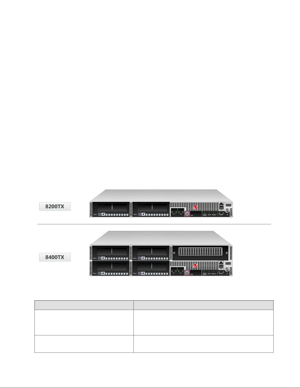
TPS TX Series devices
The TPS 8200TX and 8400TX security devices provide the following hardware features.
eature TX Series devices
F
Ports Two fixed QSFP+ special purpose (SP) ports
One RJ-45 console port
One 1 GbE copper management port
Slots • Model 8200TX – two I/O slots
• Model 8400TX – four I/O slots
1
TPS Hardware Specification and Installation
Feature TX Series devices
Power supply Two hot-swappable 750W AC power supplies
External storage One 32 GB SSD
Replaceable fans 7 hot-swappable fans
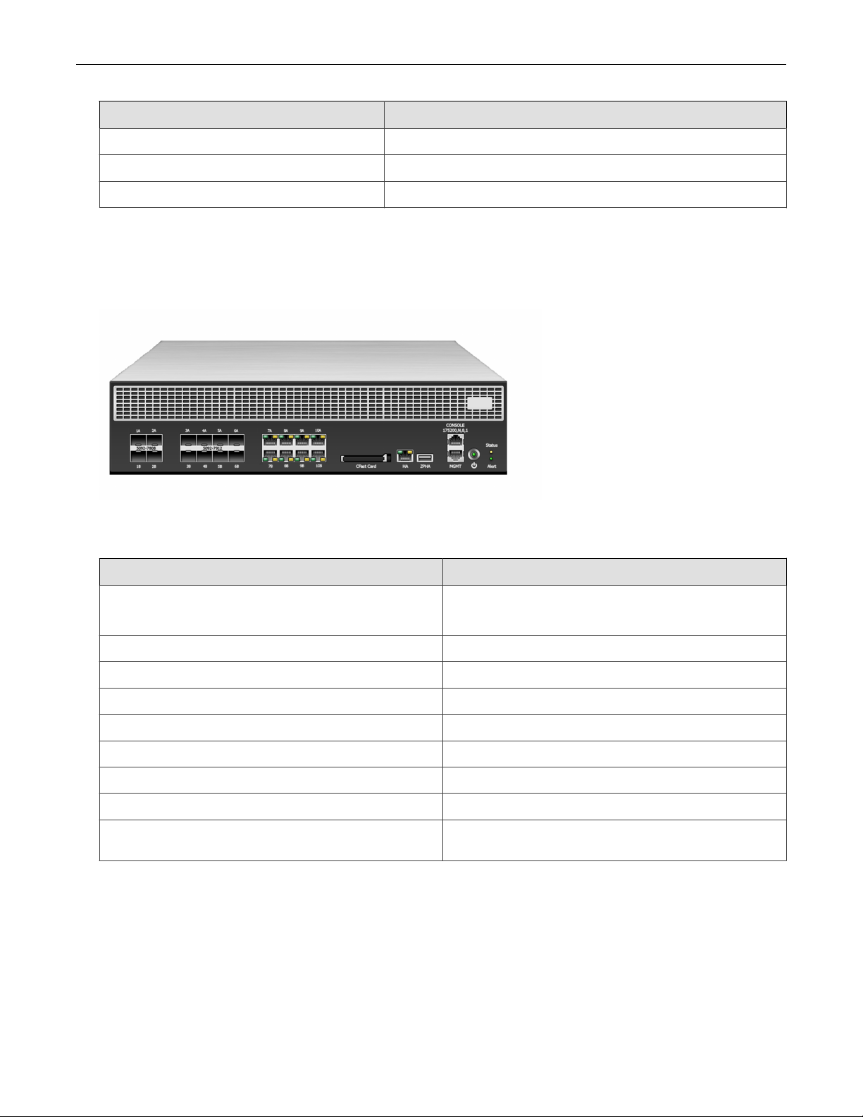
TPS 2200T device
The TPS 2200T device provides the following hardware features.
Feature 2200T device
Ports One RJ-45 console port
One 1 GbE copper management port
1 GbE copper ports 8
1 GbE SFP ports 8
10 GbE* SFP+ ports 4
Power supply 2 hot-swappable 750W AC power supplies
External storage One 8 GB CFast
System fans 3 fans (not replaceable)
Dedicated High Availability (HA) port Yes
Zero Power High Availability (ZPHA)** Built-in ZPHA for copper segments
External ZPHA port for SFP and SFP+ segments
*Rate does not include autonegotiation. Dual-rate SFP+ transceivers are not supported.
**To learn more about installing and operating a ZPHA module, refer to TippingPoint ZPHA Installation Guide – Modular and Non-Modular.
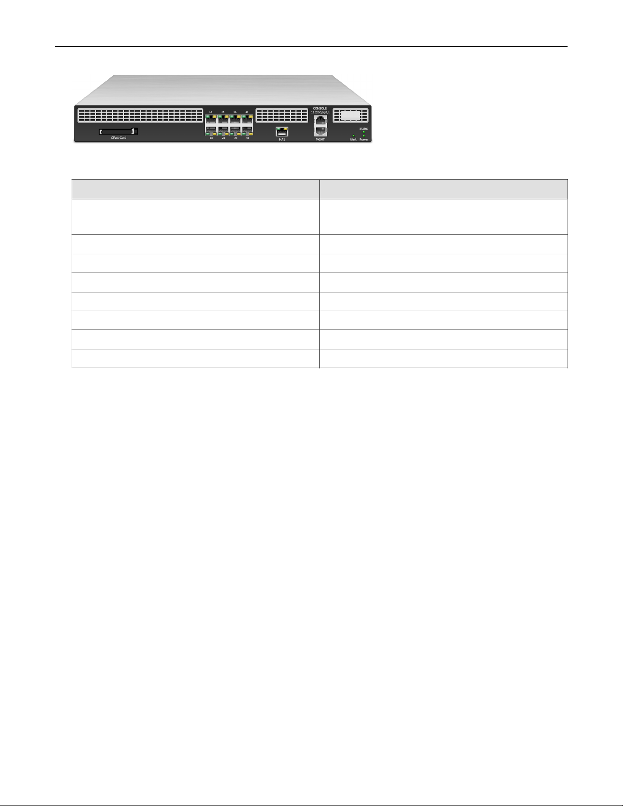
TPS 440T device
2
TPS Hardware Specification and Installation
The TPS 440T device provides the following hardware features.
Feature 440T device
Ports One RJ-45 console port
One 1 GbE copper management port
1 GbE copper ports 8
Power supply One 350W (built-in) power supply
System memory 16 GB
External storage One 8 GB CFast
System fans 3 external fans (not replaceable)
Dedicated High Availability (HA) port Yes
Zero Power High Availability (ZPHA) Built-in ZPHA for copper segments
TPS TX Series product overview
The following topics describe the components, chassis, requirements, and installation specifics of the TPS 8200TX and
8400TX devices:
• Chassis – front panel
• Chassis – rear panel
• Chassis – features
• Model requirements
• I/O module installation
• Technical specifications
Learn more about installing the device. Prior to installation, have the TPS CLI Reference available for configuration information.
3

TPS Hardware Specification and Installation
Chassis – front panel
Refer to the following illustration for a front panel view of the TX Series 1 U (8200TX) and 2 U (8400TX) devices:
1. I/O modules
2. SP ports
3. External storage 1.8-inch SSD (32 GB)
4. Stack Master LED
5. Stack LED
6. Bypass LED
7. Health LED
8. GbE management port
9. Power button
10. RJ-45 console port
4
TPS Hardware Specification and Installation
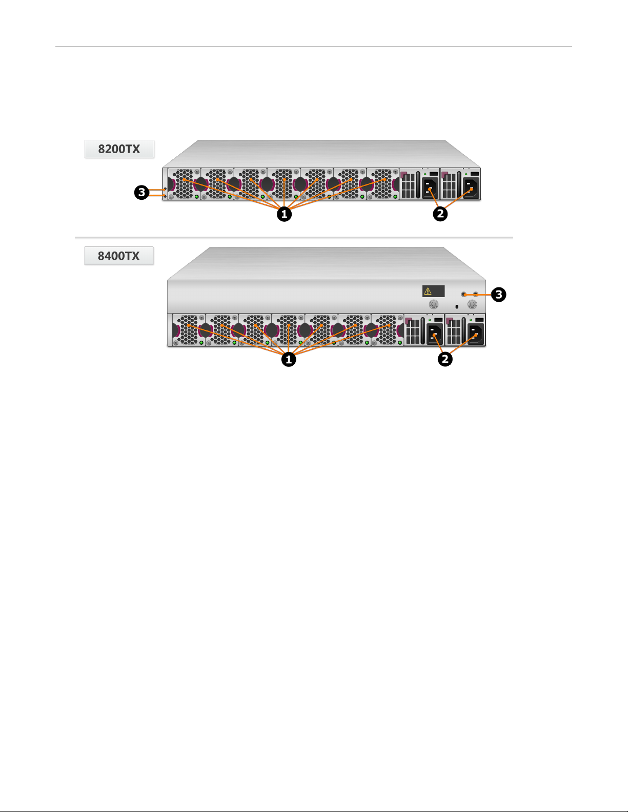
Chassis – rear panel
Refer to the following illustration for a rear-panel view of the TPS 8200TX and 8400TX devices.
1. Fan modules - fans are numbered from left to right (Fan 1 is on the left; Fan 7 is on the right)
2. Power supply modules (Power supply 1 is on the left; Power supply 2 is on the right)
3. DC grounding lug screw holes
Chassis – features
Refer to the following topics for information about the TPS TX Series chassis features:
• Fans and power supplies
• External storage card
• Ports
• Chassis LEDs
Fans and power supplies
The TPS TX Series devices include two power supplies and seven cooling fans. You can hot-swap these components. Learn
more about Power supplies and Fans.
External SSD
The TPS TX Series device includes an external SSD module that ships pre-installed with your product. The SSD is used to
store traffic logs, snapshots, and other system data. You can remove and install the card while the device is running; however,
to do so, you must issue the appropriate unmounting, mounting, and preparation commands from the device CLI.
5
TPS Hardware Specification and Installation
Learn more about these external user disk commands.
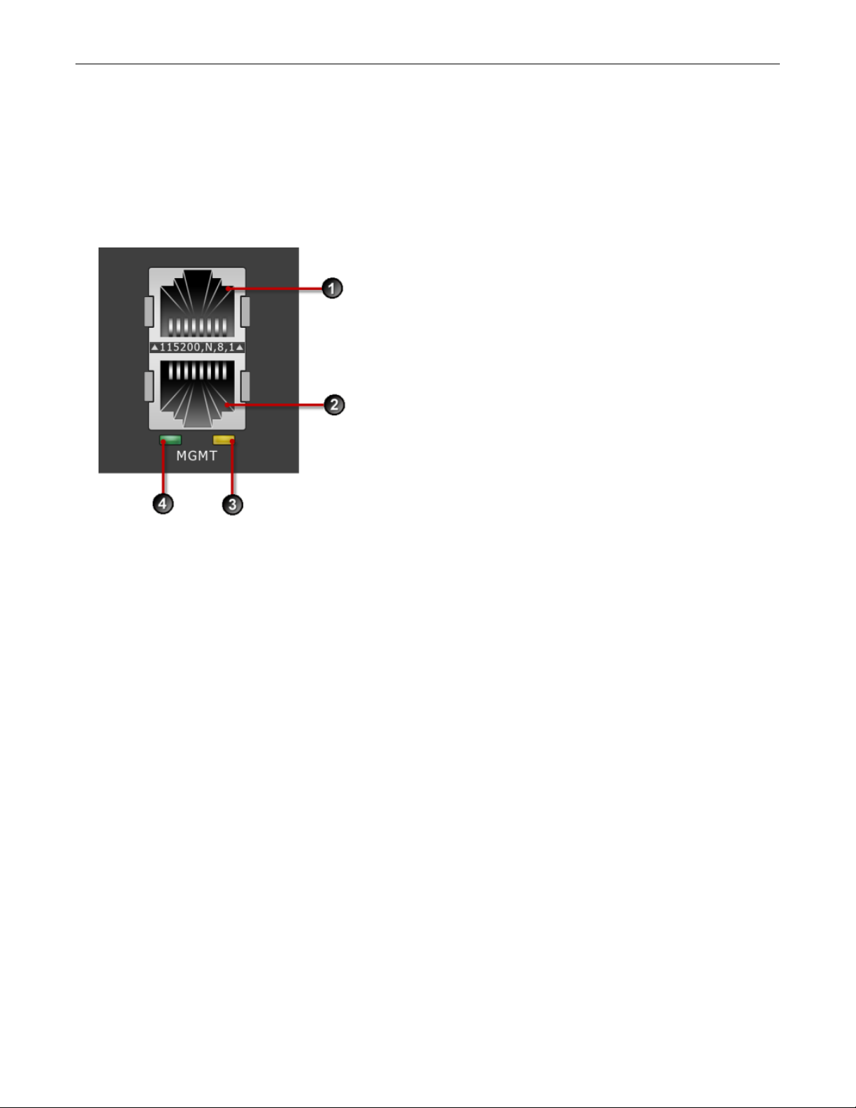
Ports
The TPS TX Series devices come equipped with network slots for standard or bypass I/O modules.
In addition, the device provides a console and management port:
1. 1 RJ-45 serial console port
2. 1 GbE copper management port
3. Activity LED
4. Link LED
Chassis LEDs
When you turn on the device, the system completes a series of component checks and then displays LED indicators to show
the status of each component:
• Stack Master status
• Solid green: The device is the stack master.
• Off: The device is not the stack master.
• Stack status
• Amber: The device is not ready to inspect network traffic.
• Flashing green: The device is RTI but is not currently inspecting network traffic.
• Solid green: The device is RTI and is inspecting network traffic.
• Off: Stacking is not enabled on the device.
• Bypass status
6

TPS Hardware Specification and Installation
• Solid red: The device is in Intrinsic High Availability (Intrinsic HA) Layer-2 Fallback (L2FB) mode.
• Off: The device is not in L2FB mode.
•
System health status
• Flashing green: The system is booting up, and is not yet ready to inspect traffic.
• Solid green: The system is healthy.
• Red: The system is experiencing a health alert, such as a fan failure. This state resets to solid green when you view
the system log.
• Management port status
• Link LED: Solid green indicates that the port is linked and ready for data.
• Activity LED: Flashing amber indicates that the port is passing data.
Model requirements
Refer to the following topics for specific requirements of the TPS TX Series devices.
• Power requirements
• Cabling requirements
Power requirements
The 8200TX and 8400TX devices require Alternating Current (AC) or Direct Current (DC) that meets the following
requirements:
• AC: Voltage 100V to 240V; 12 to 6A; 47 to 63 Hz
• DC: Voltage -40V to -60V; 24 to 16A
The TX Series devices ship with two AC power supplies. Consult your TippingPoint account contact for more information if
you require a DC power supply.
Cabling requirements
The TPS 8200TX and 8400TX devices ship with the following cables:
• Two AC power cables, one for each hot-swappable power supply
• Null modem cable (USB to RJ-45) for the serial console management port
I/O module installation
Use the following topics to set up the I/O modules supported in TippingPoint security devices:
• Before you begin
• ESD requirements
• I/O module options
7

TPS Hardware Specification and Installation
• Module LEDs
• I/O module replacement
• Supported transceivers and cables for TippingPoint I/O modules
Before you begin
• Review the release notes for your product for any late-breaking changes to the installation instructions.
• Read and follow all safety information listed in the TippingPoint Hardware Safety and Compliance Guide that shipped with
your product.
• Complete the installation of your TippingPoint security device.
ESD requirements
Damage from Electrostatic Discharge (ESD) can occur when you handle electronic components improperly. Improper
handling can also result in complete or intermittent system failures. Use proper ESD protection whenever you handle
equipment. Following these general grounding guidelines:
• Always use an ESD wrist strap when you add or remove components from the chassis.
• Avoid touching the circuit boards or connectors on all cards and modules.
• Avoid contact between the printed circuit boards and clothing. The wrist strap only protects components from ESD
voltages on the body. ESD voltages on clothing can still cause damage.
Place a removed component board-side-up on an antistatic surface or in a static-shielding container that is also grounded to
the same point as the device. If you plan to return the component to the factory, immediately place it in a static-shielding
container.
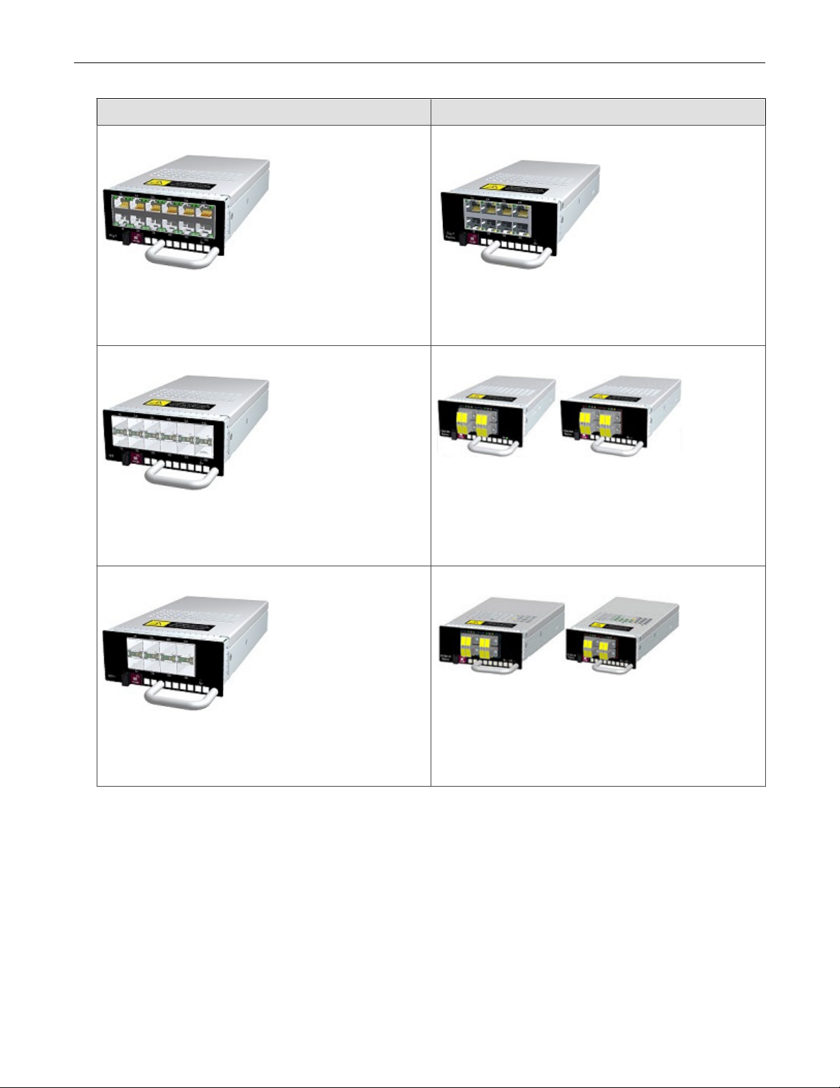
I/O module options
TippingPoint devices with module slots support both standard I/O modules and bypass I/O modules. Refer to the following
table for fiber and copper components.
Only optical transceiver modules (including SFP, SFP+, and QSFP+) available from TippingPoint have been validated to
achieve optimal performance with TippingPoint products. Other vendor devices are not supported. Using other vendor
devices could be detrimental to proper operation of the TippingPoint system.
Bypass I/O modules are zero-power high-availability (ZPHA) modules that permit network traffic and services while
bypassing the device entirely when the device loses power.
8
TPS Hardware Specification and Installation
Standard I/O Modules Bypass I/O Modules
6-Segment Gig-T
Ports: 12 Fixed RJ-45 copper ports
Port speed: 10/100/1000 Mbps
Part number: TPNN0059
6-Segment GbE SFP
Ports: 12 SFP ports
Port speed: 1 Gbps
Part number: TPNN0068
4-Segment Gig-T Bypass Module
Ports: 8 copper ports
Port speed: 10/100/1000 Mbps
Part number: TPNN0070
2-Segment 1G Fiber SR/LR Bypass Module
Ports: 4 Multi-Mode (SR)/Single-Mode (LR) Fiber (LC type)
Port speed: 1 Gbps
Part number: TPNN0071 (SR)/TPNN0072 (LR)
4-Segment 10GbE SFP+
Ports: 8 Fiber SFP+ ports
Port speed: 10 Gbps
Part number: TPNN0060
2-Segment 10G Fiber SR/LR Bypass Module
Ports: 4 Multi-Mode (SR)/Single-Mode (LR) Fiber (LC type)
Port speed: 1/10 Gbps
Part number: TPNN0073 (SR)/TPNN0074 (LR)
9
 Loading...