

Trend Micro TPS TX Series, TPS 8200TX, TPS 2200T, TPS 440T, TPS 8400TX Hardware Specification And Installation Manual
Page 1
Page 2

Privacy and Personal Data Collection Disclosure
Certain features available in Trend Micro products collect and send feedback regarding product usage and detection information to Trend Micro.
Some of this data is considered personal in certain jurisdictions and under certain regulations. If you do not want Trend Micro to collect personal
data, you must ensure that you disable the related features.
The following link outlines the types of data that the Security Management System collects and provides detailed instructions on how to disable the
specific features that feedback the information.
https://success.trendmicro.com/data-collection-disclosure
Data collected by Trend Micro is subject to the conditions stated in the Trend Micro Privacy Policy:
https://www.trendmicro.com/en_us/about/legal/privacy-policy-product.html
Legal Notice
© Copyright 2018 Trend Micro Incorporated. All rights reserved.
Trend Micro, the Trend Micro t-ball logo, TippingPoint, and Digital Vaccine are trademarks or registered trademarks of Trend Micro Incorporated.
All other product or company names may be trademarks or registered trademarks of their owners.
Publication: July 2018
Page 3
Overview
The TippingPoint Threat Protection System (TPS) is a high-performance, enterprise-class solution that protects your network
by scanning, detecting, and responding to network traffic according to the filters, action sets, and global settings maintained
on each device by a client.
The TPS offers improved technology that is optimized for higher throughput, high resiliency, high availability, and network
segment protection from both external and internal attacks.
You can install as many TPS security devices as you need to strategically protect your network enterprise zones. A local client
on the device monitors and manages activity. Alternatively, you can manage devices by using the Security Management System
(SMS) console.
Learn more about each TPS product in the following sections:
• TPS TX Series devices
• TPS 2200T device
• TPS 440T device
For information about the Virtual Threat Protection System (vTPS) virtual appliance, refer to that product documentation.
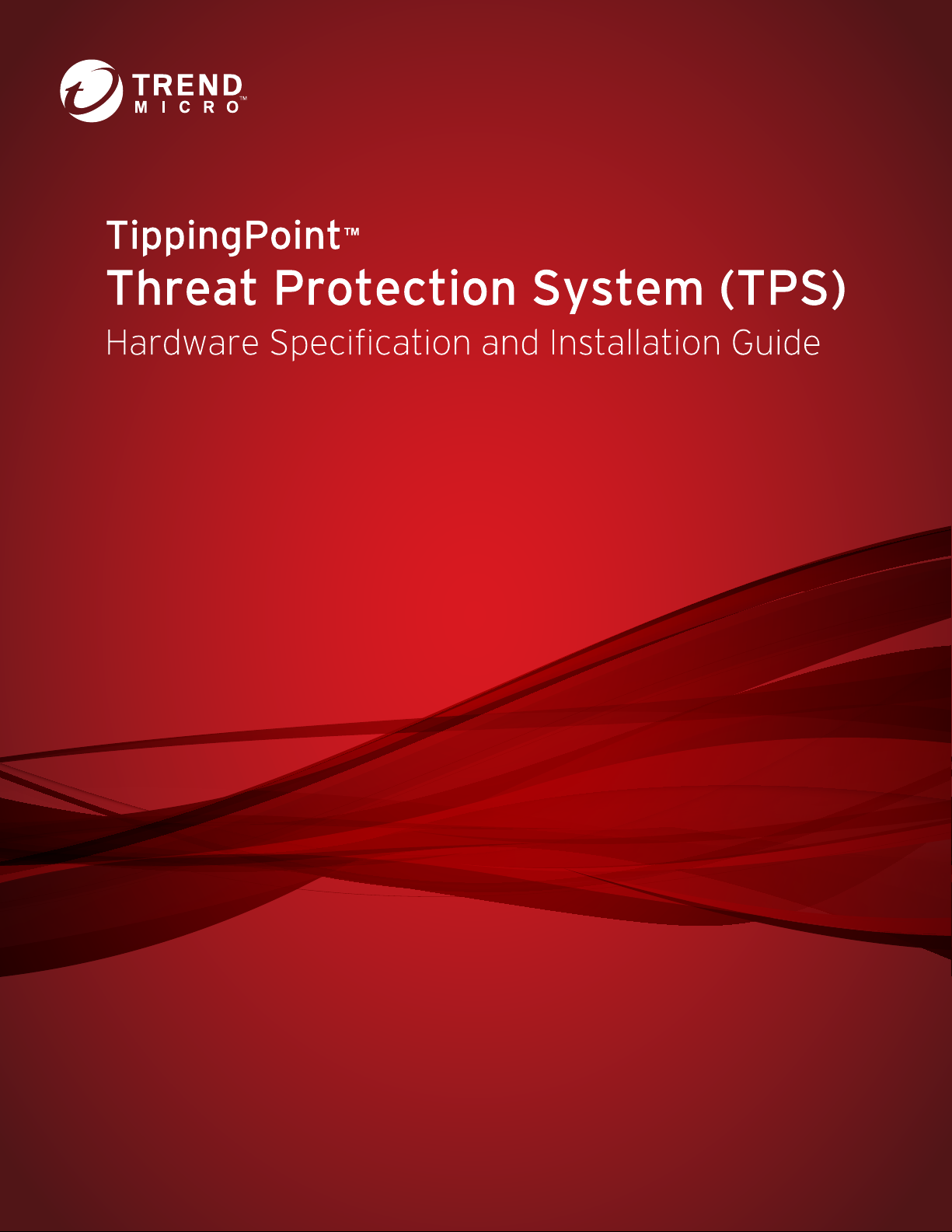
TPS TX Series devices
The TPS 8200TX and 8400TX security devices provide the following hardware features.
eature TX Series devices
F
Ports Two fixed QSFP+ special purpose (SP) ports
One RJ-45 console port
One 1 GbE copper management port
Slots • Model 8200TX – two I/O slots
• Model 8400TX – four I/O slots
1
Page 4
TPS Hardware Specification and Installation
Feature TX Series devices
Power supply Two hot-swappable 750W AC power supplies
External storage One 32 GB SSD
Replaceable fans 7 hot-swappable fans
TPS 2200T device
The TPS 2200T device provides the following hardware features.
Feature 2200T device
Ports One RJ-45 console port
One 1 GbE copper management port
1 GbE copper ports 8
1 GbE SFP ports 8
10 GbE* SFP+ ports 4
Power supply 2 hot-swappable 750W AC power supplies
External storage One 8 GB CFast
System fans 3 fans (not replaceable)
Dedicated High Availability (HA) port Yes
Zero Power High Availability (ZPHA)** Built-in ZPHA for copper segments
External ZPHA port for SFP and SFP+ segments
*Rate does not include autonegotiation. Dual-rate SFP+ transceivers are not supported.
**To learn more about installing and operating a ZPHA module, refer to TippingPoint ZPHA Installation Guide – Modular and Non-Modular.
TPS 440T device
2
Page 5
TPS Hardware Specification and Installation
The TPS 440T device provides the following hardware features.
Feature 440T device
Ports One RJ-45 console port
One 1 GbE copper management port
1 GbE copper ports 8
Power supply One 350W (built-in) power supply
System memory 16 GB
External storage One 8 GB CFast
System fans 3 external fans (not replaceable)
Dedicated High Availability (HA) port Yes
Zero Power High Availability (ZPHA) Built-in ZPHA for copper segments
TPS TX Series product overview
The following topics describe the components, chassis, requirements, and installation specifics of the TPS 8200TX and
8400TX devices:
• Chassis – front panel
• Chassis – rear panel
• Chassis – features
• Model requirements
• I/O module installation
• Technical specifications
Learn more about installing the device. Prior to installation, have the TPS CLI Reference available for configuration information.
3
Page 6

TPS Hardware Specification and Installation
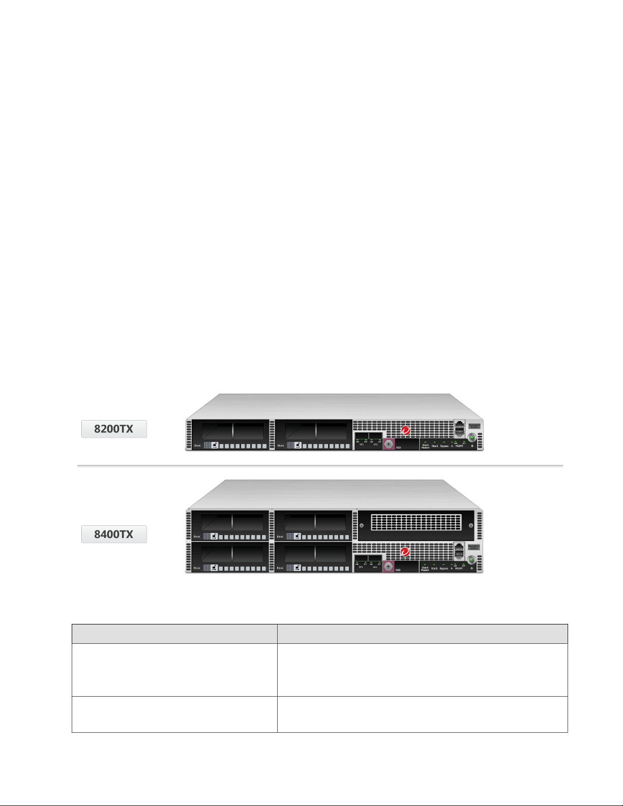
Chassis – front panel
Refer to the following illustration for a front panel view of the TX Series 1 U (8200TX) and 2 U (8400TX) devices:
1. I/O modules
2. SP ports
3. External storage 1.8-inch SSD (32 GB)
4. Stack Master LED
5. Stack LED
6. Bypass LED
7. Health LED
8. GbE management port
9. Power button
10. RJ-45 console port
4
Page 7
TPS Hardware Specification and Installation
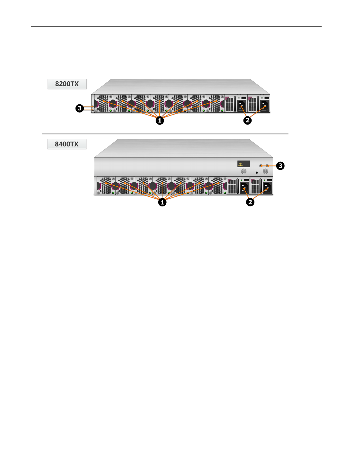
Chassis – rear panel
Refer to the following illustration for a rear-panel view of the TPS 8200TX and 8400TX devices.
1. Fan modules - fans are numbered from left to right (Fan 1 is on the left; Fan 7 is on the right)
2. Power supply modules (Power supply 1 is on the left; Power supply 2 is on the right)
3. DC grounding lug screw holes
Chassis – features
Refer to the following topics for information about the TPS TX Series chassis features:
• Fans and power supplies
• External storage card
• Ports
• Chassis LEDs
Fans and power supplies
The TPS TX Series devices include two power supplies and seven cooling fans. You can hot-swap these components. Learn
more about Power supplies and Fans.
External SSD
The TPS TX Series device includes an external SSD module that ships pre-installed with your product. The SSD is used to
store traffic logs, snapshots, and other system data. You can remove and install the card while the device is running; however,
to do so, you must issue the appropriate unmounting, mounting, and preparation commands from the device CLI.
5
Page 8
TPS Hardware Specification and Installation
Learn more about these external user disk commands.
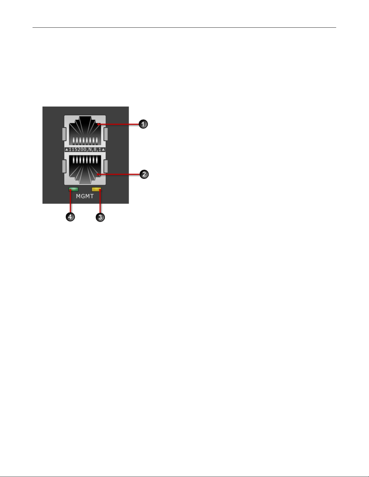
Ports
The TPS TX Series devices come equipped with network slots for standard or bypass I/O modules.
In addition, the device provides a console and management port:
1. 1 RJ-45 serial console port
2. 1 GbE copper management port
3. Activity LED
4. Link LED
Chassis LEDs
When you turn on the device, the system completes a series of component checks and then displays LED indicators to show
the status of each component:
• Stack Master status
• Solid green: The device is the stack master.
• Off: The device is not the stack master.
• Stack status
• Amber: The device is not ready to inspect network traffic.
• Flashing green: The device is RTI but is not currently inspecting network traffic.
• Solid green: The device is RTI and is inspecting network traffic.
• Off: Stacking is not enabled on the device.
• Bypass status
6
Page 9

TPS Hardware Specification and Installation
• Solid red: The device is in Intrinsic High Availability (Intrinsic HA) Layer-2 Fallback (L2FB) mode.
• Off: The device is not in L2FB mode.
•
System health status
• Flashing green: The system is booting up, and is not yet ready to inspect traffic.
• Solid green: The system is healthy.
• Red: The system is experiencing a health alert, such as a fan failure. This state resets to solid green when you view
the system log.
• Management port status
• Link LED: Solid green indicates that the port is linked and ready for data.
• Activity LED: Flashing amber indicates that the port is passing data.
Model requirements
Refer to the following topics for specific requirements of the TPS TX Series devices.
• Power requirements
• Cabling requirements
Power requirements
The 8200TX and 8400TX devices require Alternating Current (AC) or Direct Current (DC) that meets the following
requirements:
• AC: Voltage 100V to 240V; 12 to 6A; 47 to 63 Hz
• DC: Voltage -40V to -60V; 24 to 16A
The TX Series devices ship with two AC power supplies. Consult your TippingPoint account contact for more information if
you require a DC power supply.
Cabling requirements
The TPS 8200TX and 8400TX devices ship with the following cables:
• Two AC power cables, one for each hot-swappable power supply
• Null modem cable (USB to RJ-45) for the serial console management port
I/O module installation
Use the following topics to set up the I/O modules supported in TippingPoint security devices:
• Before you begin
• ESD requirements
• I/O module options
7
Page 10

TPS Hardware Specification and Installation
• Module LEDs
• I/O module replacement
• Supported transceivers and cables for TippingPoint I/O modules
Before you begin
• Review the release notes for your product for any late-breaking changes to the installation instructions.
• Read and follow all safety information listed in the TippingPoint Hardware Safety and Compliance Guide that shipped with
your product.
• Complete the installation of your TippingPoint security device.
ESD requirements
Damage from Electrostatic Discharge (ESD) can occur when you handle electronic components improperly. Improper
handling can also result in complete or intermittent system failures. Use proper ESD protection whenever you handle
equipment. Following these general grounding guidelines:
• Always use an ESD wrist strap when you add or remove components from the chassis.
• Avoid touching the circuit boards or connectors on all cards and modules.
• Avoid contact between the printed circuit boards and clothing. The wrist strap only protects components from ESD
voltages on the body. ESD voltages on clothing can still cause damage.
Place a removed component board-side-up on an antistatic surface or in a static-shielding container that is also grounded to
the same point as the device. If you plan to return the component to the factory, immediately place it in a static-shielding
container.
I/O module options
TippingPoint devices with module slots support both standard I/O modules and bypass I/O modules. Refer to the following
table for fiber and copper components.
Only optical transceiver modules (including SFP, SFP+, and QSFP+) available from TippingPoint have been validated to
achieve optimal performance with TippingPoint products. Other vendor devices are not supported. Using other vendor
devices could be detrimental to proper operation of the TippingPoint system.
Bypass I/O modules are zero-power high-availability (ZPHA) modules that permit network traffic and services while
bypassing the device entirely when the device loses power.
8
Page 11
TPS Hardware Specification and Installation
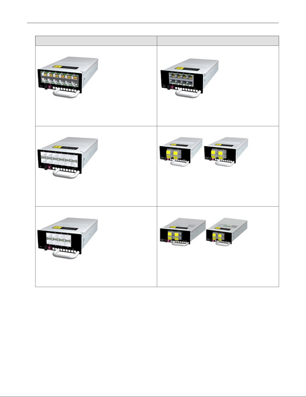
Standard I/O Modules Bypass I/O Modules
6-Segment Gig-T
Ports: 12 Fixed RJ-45 copper ports
Port speed: 10/100/1000 Mbps
Part number: TPNN0059
6-Segment GbE SFP
Ports: 12 SFP ports
Port speed: 1 Gbps
Part number: TPNN0068
4-Segment Gig-T Bypass Module
Ports: 8 copper ports
Port speed: 10/100/1000 Mbps
Part number: TPNN0070
2-Segment 1G Fiber SR/LR Bypass Module
Ports: 4 Multi-Mode (SR)/Single-Mode (LR) Fiber (LC type)
Port speed: 1 Gbps
Part number: TPNN0071 (SR)/TPNN0072 (LR)
4-Segment 10GbE SFP+
Ports: 8 Fiber SFP+ ports
Port speed: 10 Gbps
Part number: TPNN0060
2-Segment 10G Fiber SR/LR Bypass Module
Ports: 4 Multi-Mode (SR)/Single-Mode (LR) Fiber (LC type)
Port speed: 1/10 Gbps
Part number: TPNN0073 (SR)/TPNN0074 (LR)
9
Page 12

TPS Hardware Specification and Installation
Standard I/O Modules Bypass I/O Modules
1-Segment 40 GbE QSFP+
Ports: 2 Fiber QSFP+ ports
Port speed: 40 Gbps
Part number: TPNN0069
CAUTION!
Handle all I/O modules with care. The bypass modules contain mechanical switches that are very sensitive to handling when not
installed in the system. Network disruption can occur if handled improperly.
Module LEDs
Use the following table to learn about the states of each LED on the I/O module.
Feature LED Color Description
Module health Status Green
Blinking Amber
Solid Amber
Bypass Status Off
Green
The module is configured, in service, and
in good health.
The module has been inserted and
powered up, but is not yet recognized by
the software.
The module is experiencing a fault.
Module in bypass.
Module in normal mode (not in bypass).
I/O module replacement
On a TPS 8200TX and 8400TX device, hot swapping allows you to add, remove, or replace an I/O module without shutting
down the device. When the device is turned on, you can hot swap an I/O module without interruption to the TPS device.
When you hot swap an I/O module, keep the following points in mind:
• Hot-swapping I/O modules during system initialization is not supported.
• The module port configuration is always reset.
• The module segment configuration, including link-down synchronization, Intrinsic HA, and inspection bypass, is always
preserved. If you swap the module with a different type of module, be sure to verify that your segment configuration
settings have persisted.
10
Page 13

TPS Hardware Specification and Installation
When the device is turned off, cold swapping allows you to add, remove, or replace an I/O module as you would when you hot
swap. However, when you cold swap an I/O module, if the replacement module type is the same, the module port
configuration is preserved.
When the device is managed by the SMS, a delay of up to 1 minute can occur before the SMS recognizes the changed I/O
module.
When you insert a bypass I/O module, the bypass I/O module always starts up in bypass mode. A bypass I/O module
remains in bypass mode until you remove it from bypass mode through the CLI, LSM, or SMS. Rebooting the TPS does not
change the bypass mode of the bypass I/O module. For information about how to use normal mode instead of bypass mode,
refer to the SMS, LSM, or CLI documentation.
Supported transceivers and cables for TippingPoint I/O modules
For a list of supported transceivers and cables for TippingPoint I/O modules, refer to I/O Modules Overview.
Technical specifications
The TPS TX Series devices have the following specifications.
Specification Description
Dimensions
(unpackaged)
Weight • 8200TX device – 32 lbs (14.5 kg)
Power
Requirements
Service Provider
operating
requirements
External interfaces • One 1 GbE copper management port
• 8200TX device (1 U form factor) – 1.73 in x 18.54 in x 24.84 in (44 mm x
428 mm x 631 mm)
• 8400TX device (2 U form factor) – 3.46in x 18.54 in x 24.84 in (88 mm x
428 mm x 631 mm
• 8400TX device – 50 lbs (22.7 kg)
• AC: Voltage 100 to 240; Current 12 to 6 A; Frequency 47 to 63 Hz
• DC: Voltage -40 to -60, Current 24 to 16 A, SELV
The device’s maximum power consumption is 750 W.
Temperature: 32 to 104° F (0 to 40° C) — Operating
Temperature: -4 to 158° F (-20 to 70° C) — Storage
Altitude: No degradation up to 10,000 feet (3048 m)
Humidity: 5% to 95% (non-condensing)
• One RJ-45 console port
• Two fixed QSFP+ special purpose (SP) ports
• Network slots:
• 8200TX device – 2 slots
• 8400TX device – 4 slots
• 1 SSD slot
11
Page 14

TPS Hardware Specification and Installation
TPS 2200T device overview
The following topics describe the components, chassis, requirements, and installation specifics of the TPS 2200T device:
• Chassis – front panel
• Chassis – rear panel
• Chassis – features
• Model requirements
• Pluggable transceivers
• Technical specifications
Learn more about installing the device. Prior to installation, have the TPS CLI Reference available for configuration information.
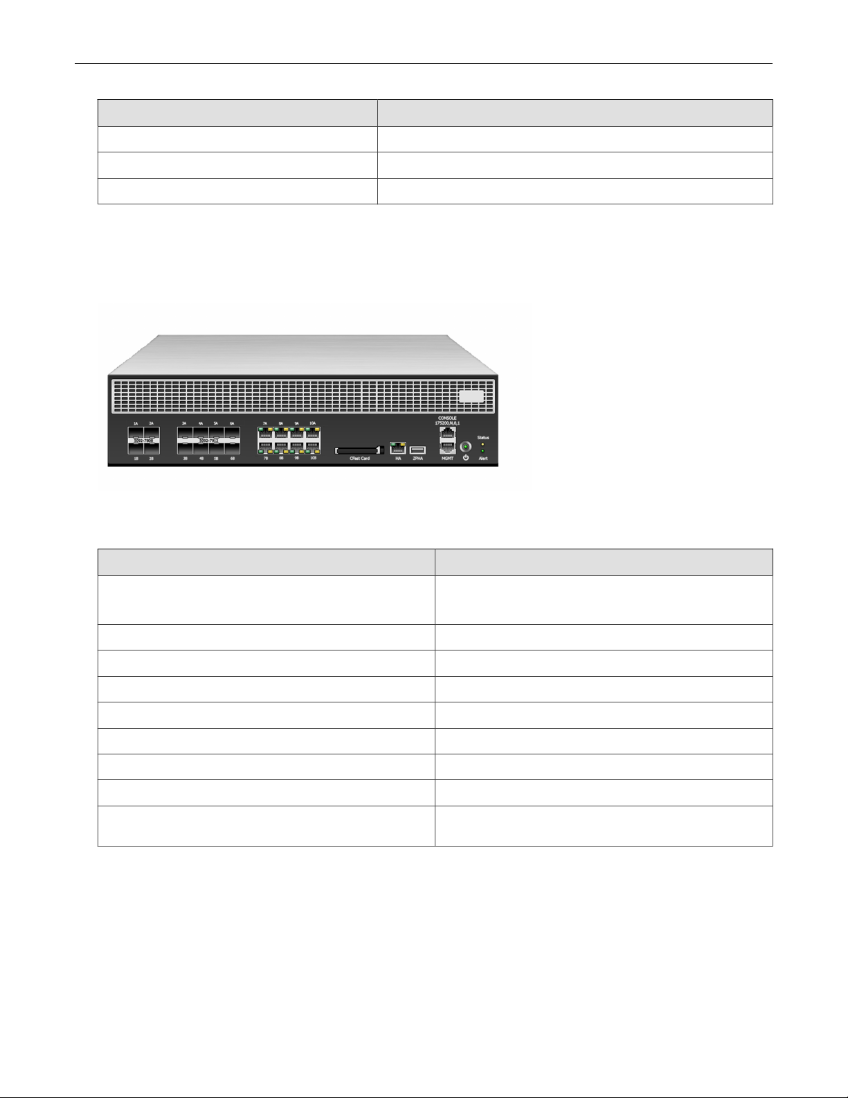
Chassis – front panel
Refer to the following illustration for a front panel view of the TPS 2200T 2 U form-factor device:
1. 10 GbE SFP+ ports
2. 1 GbE SFP ports
3. 1 GbE copper ports
4. External CFast card
5. Dedicated HA port
6. External ZPHA port
7. Console/Management port
12
Page 15

TPS Hardware Specification and Installation
8. Power button
9. Alert indicator
10. System status indicator
Chassis – rear panel
Refer to the following illustration for a rear-panel view of the TPS 2200T device.
1. Fans (3)
2. Power supplies (2)
Chassis – features
Refer to the following topics for information about the TPS 2200T chassis features:
• System status indicator
• Alert indicator
• Fans and power supplies
• External storage card
• Ports
System status indicator
Refer to the System Status indicator on the right side of the front panel to learn about the current operating status of the
device.
• Flashing Green — Device is booting and is not yet ready to inspect traffic.
13
Page 16

TPS Hardware Specification and Installation
• Solid Green — Device is running in a healthy state.
• Solid Yellow — Device is running but has a health rating below the acceptable threshold.
Alert indicator
Refer to the Alert indicator on the right side of the front panel to learn whether the device is in L2FB mode or not.
• Solid Yellow — Device is in L2FB (including when rebooting).
• Off — Device is not in L2FB.
Fans and power supplies
The 2200T device includes two hot-swappable power supplies. Learn more about these power supplies.
The 2200T device includes three cooling fans. The fans for the 2200T device are redundant but not hot-swappable. If a failure
to a fan module occurs, you must replace the entire device. Learn more about fans.
External storage card
The TPS 2200T device includes a CFast card slot. The external storage card is used to store traffic logs, snapshots, and other
system data. You can remove and insert the card while the device is running; however, to do so, you must issue the
appropriate unmounting, mounting, and preparation commands from the device CLI.
For more information, see External user disk or the TPS CLI Reference for command syntax.
Ports
The TPS 2200T device provides a console and management port as shown in the following figure.
1. 1 RJ-45 serial console port
2. 1 GbE copper management port
3. Activity LED
14
Page 17

TPS Hardware Specification and Installation
4. Link LED
In addition, the 2200T device comes equipped with eight 1G copper ports, eight 1G SFP ports, and four 10G SFP+ ports.
An external ZPHA device provides ZPHA bypass support for SFP/SFP+.
Model requirements
Refer to the following topics for specific requirements of the TippingPoint 2200T device.
• Power requirements
• Cabling requirements
Power requirements
The TPS 2200T device requires Alternating Current (AC) that meets the following requirements:
• AC: Voltage 100 V to 240 V; 12 to 6 A; 47 to 63 Hz
The TPS 2200T device ships with two AC power supplies.
Cabling requirements
The TPS 2200T device ships with the following cables:
• Two AC power cables, one for each hot-swappable power supply
• Null modem cable (USB to RJ-45) for the serial console management port
Pluggable transceivers
Use any of the following SFP and SFP+ pluggable transceivers with the TPS 2200T device:
• 1G SFP RJ45 T (Copper SFP)
• 1G SFP LC LX 10km 1310nm XCVR
• 1G SFP LC SX 550m 850nm XCVR
• 10G SFP+ LC SR*
• 10G SFP+ LC LR*
*Rate does not include autonegotiation. Dual-rate SFP+ transceivers are not supported.
Note
Only optical transceiver modules (including SFP and SFP+) available from TippingPoint have been validated to achieve optimal
performance with TippingPoint products. Other vendor devices are not supported. Using other vendor devices could be detrimental
to proper operation of the TippingPoint system.
The following table details the information for SFP and SFP+ transceivers.
iber Input Signal
F
Left side Transmit
15
Page 18

TPS Hardware Specification and Installation
Fiber Input Signal
Right side Receive
Technical specifications
The TPS 2200T device has the following specifications.
Specification Description
Dimensions
(unpackaged)
Weight 26.26 lbs (11.91 kg)
Power
Requirements
Service Provider
operating
requirements
External interfaces • One 1 GbE copper management port
2 U form factor – 3.46 in (H) x 16.77 in (W) x 18.80 in (D) (8.80 cm x 42.60 cm
x 47.80 cm)
AC: Voltage 100 to 240; Current 12 to 6 A; Frequency 47 to 63 Hz
The appliance’s maximum power consumption is 493 W.
Temperature: 32 to 104° F (0 to 40° C) — Operating
Temperature: -4 to 158° F (-20 to 70° C) — Storage
Altitude: No degradation up to 10,000 feet (3048 m)
Humidity: 5% to 95% (non-condensing)
• One RJ-45 console port
• Eight 1 GbE copper ports
• Eight 1 GbE SFP fiber ports
• Four 10 GbE SFP+ fiber ports
• One HA port
• One ZPHA port
• One CFast slot
TPS 440T product overview
The following topics describe the components, chassis, requirements, and installation specifics of the TPS 440T device:
• Chassis – front panel
• Chassis – rear panel
• Chassis – features
• Model requirements
• Technical specifications
For information about installing the device, Learn more about installing the device. Prior to installation, have the TPS CLI
Reference available for configuration information.
16
Page 19

TPS Hardware Specification and Installation
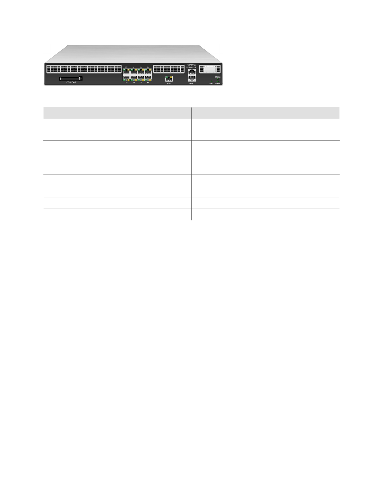
Chassis – front panel
Refer to the following illustration for a front panel view of the TPS 440T device.
1. CFast card
2. 1 GbE copper ports
3. Dedicated HA port
4. Serial console port/Management port
5. Alert indicator
6. System status indicator
7. Power indicator
Chassis – rear panel
Refer to the following illustration for a rear-panel view of the TPS 440T device.
1. Fans (3)
2. AC power supply
17
Page 20

TPS Hardware Specification and Installation
3. AC power connector
4. Power switch
Chassis – features
Refer to the following topics for information about the TPS 440T chassis features:
• System status indicator
• Alert indicator
• Fans and power supplies
• External storage card
• Ports
System status indicator
Refer to the System Status indicator on the right side of the front panel to learn about the current operating status of the
device.
• Flashing Green — Device is booting and is not yet ready to inspect traffic.
• Solid Green — Device is running in a healthy state.
• Solid Yellow — Device is running but has a health rating below the acceptable threshold.
Alert indicator
Refer to the Alert indicator on the right side of the front panel to learn whether the device is in L2FB mode or not.
• Solid Yellow — Device is in L2FB (including when rebooting).
• Off — Device is not in L2FB.
Fans and power supplies
The TPS 440T device includes one power supply and three external cooling fans. These components are not customerreplaceable. Learn more about these components.
External storage card
The TPS 440T device includes a CFast card slot. The external storage card is used to store traffic logs, snapshots, and other
system data. You can remove and insert the card while the device is running; however, to do so, you must issue the
appropriate unmounting, mounting, and preparation commands from the device CLI.
Learn more about the external storage card.
18
Page 21

TPS Hardware Specification and Installation
Ports
The TPS 440T device comes equipped with eight copper ports. In addition, the device includes the console and management
ports shown in the following figure.
1. 1 RJ-45 serial console port
2. 1 GbE copper management port
3. Activity LED
4. Link LED
Model requirements
Refer to the following topics for specific requirements of the TPS 440T device.
• Power requirements
• Cabling requirements
Power requirements
The TPS 440T device requires Alternating Current (AC) that meets the following requirements:
• AC: Voltage 100 V to 240 V; 4 to 2 A; 47 to 63 Hz
The TPS 440T device ships with one AC power supply.
Cabling requirements
The TPS 440T device ships with the following cables:
• One AC power cable
• Null modem cable (USB to RJ-45) for the serial console management port
19
Page 22

TPS Hardware Specification and Installation
Technical specifications
The TPS 440T device has the following specifications.
Specification Description
Dimensions
(unpackaged)
Weight 15.28 lbs (6.93 kg)
Power Requirements AC: Voltage 100 to 240; Current 4 to 2 A; Frequency 50 to 60 Hz
Service Provider
operating
requirements
External interfaces • One 1 GbE copper management port
1 U form factor – 1.73 in (H) x 16.78 in (W) x 17.72 in (D) (4.40 cm x 42.62 cm x
45.00 cm)
The device’s maximum power consumption is 250 W.
Temperature: 32 to 104° F (0 to 40° C) — Operating
Temperature: -4 to 158° F (-20 to 70° C) — Storage
Altitude: No degradation up to 10,000 feet (3048 m)
Humidity: 5% to 95% (non-condensing)
• One RJ-45 console port
• Eight 1 GbE copper ports
• One CFast slot
Install your TPS device
After you have completed preparation procedures and unpacked the TPS device, you can install and configure the
components. Have the TPS CLI Reference available for configuration information reference. After installation of the hardware
components, complete the initial setup wizard as part of the installation and configuration procedures.
Before installing your device, review and adhere to all safety guidelines described the TippingPoint Hardware Safety and
Compliance Guide, which also contains detailed regulatory compliance information and is included with your product shipment.
Follow these installation procedures:
• Install the chassis
• Connect the power supply
• Attach the cables
• Run the setup wizard
Install the chassis
Before installing your new security device, gather any necessary materials and prepare the network and hardware site. To
carefully and correctly install the device, read through all preparation instructions and requirements. Use this general guideline
information for all TippingPoint devices. For installation guidelines specific to your TPS device, refer to the appropriate Install
your security device quick start for your model.
To install the device you must complete the following procedures:
• Determine total rack space
20
Page 23

TPS Hardware Specification and Installation
• Attach the device to the rack
• Connect the power supply
Determine total rack space
Before you install the chassis, determine the total rack space required to install your system. The total required rack space
increases if you plan to install multiple systems.
The device fits in a 19-inch-wide rack (or a 23-inch-wide rack, with appropriate conversion parts available from rack accessory
vendors). For more information about the dimensions of the device, refer to the technical specifications and requirements for
your model.
Attach the device to the rack
Unpack the accessory kit and the slide rail assemby kit that shipped with your security device and review the installation
documentation.
If the rack is partially filled, load the rack from the bottom to the top with the heaviest component at the bottom. During
initial installation, make sure to evenly distribute the weight so that the rack is stable.
Important
Always use a four-post mount for four-post racks.
If you plan to expand your system to include additional TippingPoint systems in the future, allow space in the rack for
additions. During the initial installation, keep in mind the weight distribution and stability of the rack.
Install the external storage card
For TPS 440T and 2200T security devices, install the CFast card that was packaged with your product into the empty slot on
the front panel of the device. Use this pre-formatted, hot-swappable user disk to store system logs, snapshots, and other
system data.
The external SSD module comes pre-installed in the TPS 8200TX and 8400TX security devices. If you have a TPS TX Series
device, you can skip this step.
Connect the power supply
After you have bolted the device to the rack, attach the power supply AC connections. Do not turn on the device until you
have completed all of the remaining installation steps.
The TPS 2200T, 8200TX, and 8400TX security devices require the use of one power cord to turn on the device. Use a
second power cord for redundancy. For maximum protection, use different power circuit feeds for each power cord.
The TPS 440T provides a single power supply.
When you install DC power, always install the safety ground cable before connecting the power supply. For DC power
connection details, refer to the Install your power supply module documentation.
To connect the power supply
21
Page 24

TPS Hardware Specification and Installation
Procedure
1. Locate the power inlets on the back of the chassis.
2. Plug the female end of a standard power cord into the power inlet. Plug the other end of the power cord into an AC
outlet, power strip, or UPS.
Add the I/O modules – TPS TX Series
TPS TX Series devices come with blank modules inserted into I/O module slots. The TPS 8200TX provides two I/O slots
and the TPS 8400TX provides four I/O slots.
WARNING!
Do not leave slots empty for an extended period of time. Insert a blank module or I/O module so that the device can be correctly
cooled. Learn more about I/O module installation.
Procedure
1. To remove the blank module, slide the slide latch (1) to the right and pull on the handle (2 on left module) or grab point
(2 on right module).
CAUTION!
Never lift your device using the module handles.
2. To insert an I/O module, slide the module into the empty module slot.
When the module is in the correct position, the slide latch automatically slides into position.
When you insert a bypass I/O module, the bypass I/O module always starts up in bypass mode. A bypass I/O module
remains in bypass mode until you remove it from bypass mode through the CLI, LSM, or SMS. Rebooting the TPS device
does not change the bypass mode of the bypass I/O module. For information about how to use normal mode instead of
bypass mode, refer to the SMS, LSM, or CLI documentation.
22
Page 25

TPS Hardware Specification and Installation
Attach the cables
During initial setup, use the console port to access the setup wizard.
Connect the console port
Procedure
1. Connect the RJ-45 null modem cable to the console port on the front of the unit.
2. Connect the other end of your cable (standard USB connector) to your computer.
Use the following terminal settings for the console port:
• Baud rate: 115.2 Kbps
• Character size: 8 bits
• Parity: None
• Stop Bits: One
• Flow Control: None
Connect the management port
Procedure
1. Connect one end of the Category 5 Ethernet cable to the port labeled MGMT located on the front panel.
2. Connect the other end of the Ethernet cable to your network. This enables remote management.
Turn on the device
After you have reviewed all requirements for operating your product, turn on the device:
• To turn on a TPS 440T device, flip the power switch on the back panel of the device.
• To turn on a TPS 2200T, 8200TX, or 8400TX security device, use the power button located on the front panel of the
device.
Important
When you shut down the TippingPoint Operating System (TOS) using the halt command, the device still has power. Before you
can restart a device in this state, you must first remove power completely for 60 seconds. For 440T devices, either unplug the device or turn off
the power using the power switch on the back panel of the device. For 2200T and TX Series devices, you can remove power by
holding down the front panel power button for 5 seconds.
Run the setup wizard
From the console terminal, complete the initial configuration by using the setup wizard. The wizard performs system checks
and then prompts you to complete the initial setup.
23
Page 26

TPS Hardware Specification and Installation
After you run the setup, you can further configure your system using subsequent setup commands through the device CLI.
See the TPS Command Line Interface Reference for detailed command descriptions.
1. Specify a security level (None, Low, Medium, or High). The security level you select determines your password
complexity requirements.
2. Create an administrative account with the SuperUser role. The SuperUser role gives the account full access to the
device. For more information about user accounts, review the documentation for your product.
The wizard prompts you to log in with your administrative account so that you can continue initial setup.
3. From the console port terminal, log in with your administrative account.
The wizard prompts you to configure IP address, default gateway, DNS server, and timekeeping options.
Install your license package
Install your license package on the device to provide the following product capabilities:
• Inspection throughput
• Digital Vaccine (DV)
• Threat Digital Vaccine (ThreatDV)
• SSL inspection
You can install the license package using the SMS or LSM. For information about how to install the license package, refer to
the user guide for whichever interface you use.
Update your license package to assign a product capability that you have purchased, such as an inspection throughput license,
to a particular security device. To review and manage the capabilities in your license package, go to the TippingPoint License
Manager on the
TMC.
Verify your product license provides sufficient inspection throughput. By default, a TPS security device is unlicensed and
provides reduced inspection throughput for testing and evaluation purposes only.
Security device Unlicensed inspection throughput
8400TX 1 Gbps
8200TX 1 Gpbs
2200T 200 Mbps
440T 100 Mbps
Attach network connections
Attach your network cables to network segments on the device where appropriate.
Where to go next
After you attach network connections, network traffic passes through the device using the default filter configuration. The
default configuration automatically recognizes and blocks traffic that is known to be malicious at all times, under all
conditions, in all network environments.
24
Page 27

TPS Hardware Specification and Installation
On a TX Series device, any bypass I/O modules remain in bypass mode until you remove them from bypass mode through
the CLI, LSM, or SMS. Rebooting the TPS does not change the bypass mode of the bypass I/O module. For information
about how to disable bypass mode, refer to the SMS, LSM, or CLI documentation.
To complete your installation, refer to the Release Notes for your product. The Release Notes provide the latest post-installation
information for your product.
You can perform additional configuration, administrative, and management tasks, by using:
• The LSM or the device CLI. The LSM and CLI enable straightforward management of a particular device.
Note
From the CLI, you can repeat the setup wizard by using the setup command. When you use the CLI, configure the terminal
emulation package to transmit a Ctrl-H character when the Backspace key is pressed.
• The SMS. The SMS provides a scalable, policy-based operational model, and enables straightforward management of
large-scale IPS and TPS deployments.
Power supplies
The following topics provide information for using the power supply modules:
• AC power supply – TPS 2200T and TX Series
• DC power supply – TPS TX Series
WARNING!
Your product might have more than one power supply source. All power sources must be removed to de-energize the unit.
The TPS 2200T device has hot-swappable power supplies; there are no other serviceable parts inside. There are no hotswappable or serviceable parts inside the TPS 440T device.
AC power supply – TPS 2200T and TX Series
The TPS 2200T and TX Series devices include two power supply modules. The modules are hot-swappable, redundant, and
current-sharing, and the appliance can run with one active module.
25
Page 28

TPS Hardware Specification and Installation
1. Removal Latch
2. Handle
3. Status LED
4. AC male power input
The Status LED is green when the module is powered and running normally.
Connect the AC power supply
When the AC power supply has been securely placed in the device, use the following procedure to connect power to the AC
power supply:
Procedure
1. Locate the male power input on the back of the chassis.
2. Plug one end of a standard female power plug into the power input.
3. Plug the other end into an AC outlet, power strip, or UPS. Learn more about the power requirements for your product:
• TX Series devices – Technical specifications
• 2200T device – Technical specifications.
• 440T device – Technical specifications
The TPS device returns to its previous power-on state in the event of a power interruption. If power was on when the
interruption occurred, the device automatically powers back on when the power is reconnected; if power was off, the
device stays off when the power is reconnected. If necessary, power on the device with the button on the front of the
chassis.
DC power supply – TPS TX Series
The TPS TX Series devices are NEBS compliant and can accept a combination of AC and DC power supply units. Consult
your TippingPoint account contact for more information on obtaining DC power supplies.
WARNING!
Do not attempt to install a DC power supply into a 440T device. The 440T device does not contain the grounding capability for safe
installation of a DC power supply. Bodily harm and damage to the system could result.
Connect the DC power supply
WARNING!
When installing the product, always make the ground connection before applying power to the unit. You must ground this
equipment to an external ground connection. Use a green and yellow 12 AWG ground wire to connect the host to earth ground
during normal use. Disconnect the ground connection only after the unit is completely powered down.
26
Page 29

TPS Hardware Specification and Installation
CAUTION!
Do not attach a ground wire to the ground screw on the DC power supply module. Attach the ground wire to the 2200T chassis DC
grounding screw holes (0.63-inch hole spacing) with #10 screws. The DC grounding screw holes are located in the rear of the
chassis.
The power supply LED is green when the module is powered and running normally.
When the DC power supply has been securely placed in the device, use the following procedure to connect power to the DC
power supply.
Procedure
1. Locate the ground screw on the back of the chassis.
Refer to the following figure for the location.
2. Attach a 12 AWG ground wire to the chassis ground strap mounting.
The wire should be crimped with a ring lug.
3. Locate the power input terminal block on the back of the module.
4. Attach the 12 AWG DC power wires to the power input terminal block labeled -48V and RTN.
The power wires should be crimped with lug spades to ensure a secure connection.
5. Connect the other side of the power cable to the SELV power source.
The power source should meet the following requirements:
• Voltage: -40 to -60 V
• 24 to 16 Amps
• SELV
27
Page 30

TPS Hardware Specification and Installation
6. Depending on the BIOS settings and the state the device was in when the power was unplugged, the device might or
might not turn on automatically when you reapply power. If necessary, power on the device with the button on the front
of the chassis.
Fans
The 440T device includes five cooling fans (two of them are internal). The fans are not redundant or hot-swappable. If a
failure to a fan module occurs, you must replace the entire device.
The 2200T device includes three cooling fans. The fans for the 2200T device are redundant but not hot-swappable. If a
failure to a fan module occurs, you must replace the entire device.
The TPS TX Series devices include seven cooling fans. The fans for the 8200TX and 8400TX devices are redundant and hotswappable. You can replace an individual fan without powering down the device.
The TPS TX Series Spare Fan (TPNN0266) is a replacement unit and can only be used with TPS TX Series devices.
When a fan module fails or its RPM rate falls below a certain threshold, the system generates a warning or critical alarm
message in its logs.
You can check fan performance by using:
• The LSM: System Health > Monitor > Fan Speed
• The device CLI: show health fan
Replace the fan – TPS TX Series
The TPS 8200TX and 8400TX fan modules are hot-swappable and you can replace them when the device is operating.
For more information about identifying and replacing faulty fan modules, refer to Install your fan module.
Power cord retention bracket
The power cord retention bracket prevents the power cords from being too obtrusive. It also helps reduce strain on the
power cord and power supply outlets.
28
Page 31

TPS Hardware Specification and Installation
Use the information in the following topics to manage the power cord retention bracket:
• Install the retention bracket
• Attach the power cord retention bracket
• Remove the bracket
Install the retention bracket
The following figure shows the back panel of a TPS 2200T device with the power cord retention bracket installed:
To install the retention bracket:
Procedure
1. Orient the bracket against the back surface of the chassis.
2. Slide the bracket over the two shoulder rivets on the back of the chassis.
The spring-loaded plunger in the center of the bracket slides into place.
29
Page 32

TPS Hardware Specification and Installation
Attach the power cord retention bracket
Follow this procedure to attach the power cord to the retention bracket:
Procedure
1. Fold the power cable and slide it into the slot.
2. Push the folded cable into the slot until the cable loop goes past the sheet metal tabs.
3. Secure the folded cable loop under the sheet metal tabs and attach the power cable to the power supply.
Remove the bracket
If you need to remove one of the brackets, pull the spring-loaded plunger in the middle of the bracket and slide the bracket
up and off the shoulder rivets.
External user disk
The following topics provide information about the external user disk (CFast or SSD):
• External SSD
• External CFast storage card
• External user disk commands
External SSD
The TPS TX Series devices come with a pre-formatted external SSD.
Use the 32 GB external SSD to store traffic logs, snapshots, and other system data.
Only SSDs available from TippingPoint have been validated to achieve optimal performance with TippingPoint products.
Other vendor drives are not supported. Using other vendor drives could be detrimental to proper operation of the
TippingPoint system.
You can replace the SSD when the system is operating.
CAUTION!
Before you remove the SSD, use the device CLI to first unmount the drive. Failure to properly remove the TippingPoint SSD can
result in disk corruption and a system error. Learn more about using the external user disk commands.
After you insert a new SSD module into the SSD slot, be sure to mount the user disk using the device CLI. Failure to mount
the user disk prevents the device from automatically mounting the disk when you reboot the device.
External CFast storage card
The TPS 440T and 2200T devices come with a pre-formatted external CFast storage card.
Use the 8 GB external CFast card to store traffic logs, snapshots, and other system data.
30
Page 33

TPS Hardware Specification and Installation
Only CFast cards available from TippingPoint have been validated to achieve optimal performance with TippingPoint
products. Other vendor cards are not supported. Using other vendor cards could be detrimental to proper operation of the
TippingPoint system.
You can replace the CFast card when the system is operating.
CAUTION!
Before you remove the card, use the device CLI to first unmount the user disk. Failure to properly remove the TippingPoint CFast
card can result in disk corruption and a system error. Learn more about using the external user disk commands.
After you insert a new card into the CFast slot, be sure to mount the user disk using the device CLI. Failure to mount the user
disk prevents the device from automatically mounting the disk when you reboot the device.
External user disk commands
The following table provides information about the commands used to manage the external user disk (CFast or SSD) in the
CLI.
Refer to the TPS CLI Reference for detailed documentation of these commands.
Command Description
user-disk format Formats the external user disk. This command erases any
existing data on the external user disk.
user-disk mount Manually mounts the external user disk.
If you replace the external user disk while the device is turned
off, be sure to also restore power to the device so that you can
mount the replacement disk. Failure to mount the replacement
disk prevents the device from automatically mounting the disk
when you reboot the device.
user-disk unmount Unmounts the external user disk so that the user can remove it.
user-disk encryption enable Encrypts the external user disk if the system master key has
been set. Changing the encryption status reformats the external
user disk and erases all data on the drive.
You can also configure master key and encryption controls using
System > Settings > Data Security in the LSM. For more
information, refer to the TPS Local Security Manager User
Guide.
user-disk encryption disable Disables encryption of the external user disk if the system
master key has been set. Changing the encryption status
reformats the card and erases all data on the drive.
You can also configure master key and encryption controls using
System > Settings > Data Security in the LSM. For more
information, refer to the TPS Local Security Manager User
Guide.
show user-disk Shows properties of the external user disk, including operation
status and capacity.
31
Page 34

TPS Hardware Specification and Installation
Command Description
master-key set Encrypts the external user disk and the system keystore by
using the system master key. You are prompted to enter a
master key that is between 9 and 32 characters in length,
contains a combination of numbers and uppercase and
lowercase letters, and that has at least one special character (for
example, !@#).
You can also configure master key and encryption controls using
System > Settings > Data Security in the LSM. For more
information, refer to the TPS Local Security Manager User
Guide.
32
 Loading...