

Page 1
ACCESSIBLE BATHTUB REPLACEMENT SHOWER
STORAGE AND HANDLING OF FOUR PIECE SHOWER UNITS
Most handling damage is the result of impact blows to the back side of the fiberglass units.
1.
These sectional units are typically unpacked and unbolted so the separate parts may be moved to the installation
2.
area. Please use caution when unbolting the sections. Carry the parts with minimal flexing to avoid stress cracks.
(Measure and mark supply valve and shower head locations before unbolting).
Placing objects inside the unit can cause scratches or nicks to the finished surface.
3.
Do not use the shower as a trash receptacle! Always place a drop cloth or cardboard
inside the shower.
Storing units outside right-side up can cause sunlight to discolor the gelcoat finish. Also, unit becomes unstable
4.
and is easily knocked over by wind or bumping.
The back of a fiberglass unit is not waterproof. Unit must be stored so water will drain off and not accumulate
5.
in one spot. Water can permeate the back laminates and soak the glassed in wood or cardboard supports causing
bulges in the gelcoat surface.
Never drag a fiberglass unit on any surface. Always transport the unit by hand using (2) people or two wheel dolly.
6.
Never let a fiberglass unit drop from any height, not even an inch or stress cracks are likely to occur.
7.
on the floor when working
Never clean fiberglass gelcoat surface with metal tools of any kind, including razor blades.
8.
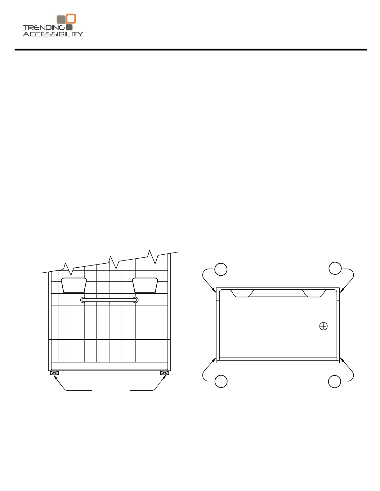
VERY IMPORTANT FOR LOW THRESHOLD SHOWER:
FRONT VIEW
Proper
Block
Placement
2
1
TOP VIEW
4
3
The low threshold shower model: 6030BF1.0 must be stored with special care. During storage, this unit should
never sit as it was received. It should be stored with a 2” x 4”
point
s numbered above in the top view
the floors. By placing the unit on blocks, the molded drain will not rest on the floor. This
to be maintained without the weight of the shower unit pushing the drain upward. The blocks should only be placed at
the outside corner edges of the unit and should not be placed under the middle of the threshold. This procedure should
only be used during storage and not for installation. Certain units may ship with a template under them to prevent the
drain from resting on the floor. This template should remain attached during storage and removed just before installation.
. Unit
s having altered threshold height
block of some other type of material at each of the (4)
s do not have wooden bottoms to reinforce
allow
will
1
856-488-9535 www.TrendingAccessibility.com
the draft of the floor
Page 2
PLANNING YOUR INSTALLATION
Carefully remove the old bathtub at the installation site. The replacement showers are 82” tall so wall board should
1.
be removed on all three walls to at least this height.
The shower unit must be disassembled for installation. All joints must be caulked as they are installed. When
2.
moving the parts, take care to avoid striking the edges of the wall sections to prevent chips or cracks.
Study Framing Diagrams on Page 3 of this manual. Adjust drain and water supply locations if required.
3.
Cutout in floor for drain requires a minimum size of 10” x 10”.
Modify framing if required. There should be a framing member behind each flange. Make sure your framing
4.
is plumb and square.
Planning is necessary for Thin-Set mortar to be placed in the drain core area for all installations. Proper blocking
5.
is required to prevent the Thin-Set from flowing to the floor below.
For installation of showers without Easy Base, wet Thin-Set mortar must be placed under the shower bottom to provide
structural support, and to maintain factory slope to the drain. See Figure 2.
Showers configured with the factory installed Easy Base TM self leveling, reinforced bottom will be installed using
panel adhesive. However, wet mud will be used in the drain core area on these units. See Figure 3.
For ALL installations, apply a heavy bead of polyurethane panel adhesive under the shower threshold.
INSTALLATION INSTRUCTIONS
Before you disassemble the shower unit, transfer the locations for the supply valve and shower head on the unit.
1.
Mark these locations on the back (reinforced surface) of the unit. After double checking the locations, drill 1/4”
pilot holes.
Always place cardboard or a drop cloth in the shower base to protect the finished surface. Working from the finished
2.
side of the unit, using the proper size hole saw, cut holes for supply lines and shower head.
Remove the connection bolts and disassemble the unit. If present, remove shower rod. Carefully carry the parts
3.
to the installation area. Do not flex the parts when moving to avoid scratches and stress cracks.
The shower parts may be caulked, reassembled and installed in one piece if there is sufficient room. Typically,
4.
the parts are installed piece by piece starting with the base.
be used for permanent connection. The installer must apply 100% silicone caulking to all connection surfaces for
final installation. If installing piece by piece, or as one piece, support under the unit must be provided as described
below. The support is necessary to assure factory slope to the drain is maintained.
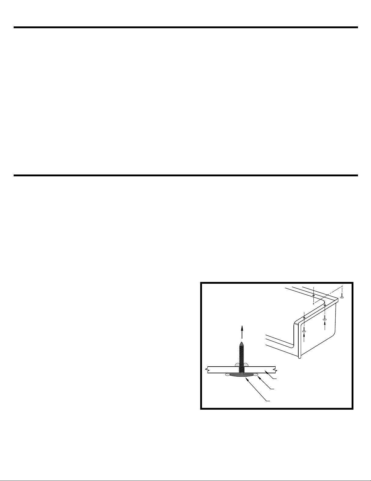
When installing piece by piece, use the plastic fasteners
5.
in place of the nuts and bolts. The fasteners will act as
guides that will index the parts together for installation
where access to the back side in unavailable.
Apply a liberal amount of 100% silicone caulk to each
6.
fastener before inserting them through the holes.
See Figure 1.
If installing in one piece, the metal nuts and bolts must
Insert the plastic fasteners through the holes from
below so they point to the ceiling.
Insert plastic fasteners through the holes in the vertical
7.
mounting surfaces on each side of the back wall. These
must be inserted from the back so they point toward
the front of the shower. Again, apply 100% silicone caulk
to the fasteners before inserting them through the holes.
NOTE: The caulking must be allowed to cure before
assembly of the unit.
Figure 1
Fiberglass Shower
Silicone Bead
Plastic Fastener
Carefully position the shower base so it sits on the front mounting flanges. Install the drain fitting in accordance
8.
with instructions provided with the fitting. Do not allow the base to sit on the drain fitting.
Study Framing Diagrams Figures 2 and 3 and note the important installation requirements.
9.
Unless the shower is caulked and parts fastened together with nuts, washers and bolts as a one piece unit, the
shower base is installed separately from the wall sections. Before applying any Thin-Set or Adhesive, trial fit the
shower
Make any adjustements at this time.
base to confirm the alcove is of proper size and the drain is located properly.
2
856-488-9535 www.TrendingAccessibility.com
Page 3

FRAMING DIAGRAM FOR BATHTUB REPLACEMENT SHOWER
Example of Mortar Thin Set Pattern
Laticrete thin set
mortar troweled
under shower.
Include drain core
Blocking
between studs
to secure the
mounting flange
Box out for
sub floor
plumbing.
10” x 10” core
size required
Note that thin set
mortar must be
applied to the drain
core area
3M polyurethane adhesive
heavy bead applied under
the shower threshold
(Without Easy Base)
Figure 2
10.
11.
12.
13.
14.
Before beginning final installation, it is ESSENTIAL that the sub floor in the installation area be completely clean.
It must be free of all dirt, trash, oil, grease, water and other contaminants that may
Thoughly clean the area before proceeding with the shower installation.
Note that for ALL installations, Thin-Set mortar is used in the Drain Core area. Fill the drain core only 2/3rds full
of Thin-Set. Do not overfill as this will prevent proper floor draft and may push
not to drain properly. Make sure you block off the drain core to prevent the Thin-set from escaping to the floor
below.
Note that for ALL installations, 3M Polyurethane Adhesive (or equivelent) is use to adhere the shower threshold
to the sub-floor.
the drain area up causing the unit
affect adhesion.
Installation of Units Without Easy Base
When installing showers without the factory Easy Base, wet Thin-Set mortar must be appled to the sub-floor to
provide support of the shower base. The Thin-Set should be applied
in place. This Thin-Set should be thick enough to assure it will contact the bottom of the shower, but be plyable
enough so it may be dispalced as the shower is leveled.
Apply a thick bead of 3M Polyurethane Adhesive (or equivelent) along the sub-floor where the shower threshold
will be located as illustrated in Figure 2.
After blocking the drain core, apply the appropriate amount of Thin-Set in the drain core area. Then appy the
Thin-Set mortar to the installation area, as shown
(or equivelent) at the front where the shower threshold will be located.
Carefully lift the shower base into the framing alcove. Guide the shower drain pipe with a hammer handle or
equivelent. The entire bottom of the shower must be in contact with the Thin-Set mortar. The front threshold must
seat into the heavy bead on 3M adhesive.
in Figure 2. Apply a wide bead of 3M polyurethane adhesive
immediately before the shower base is set
Installation of Units With Factory Easy Base
15.15.
16.
After blocking the drain core, apply the apropriate amount of Thin-Set in the drain core area. Then appy the
adhesive to the installation area as shown in Figure 3. Use a notched trowel to spread the adhesive. Apply a wide
bead of
Carefully lift the shower base into the framing alcove. Guide the shower drain pipe with a hammer handle or
equivelent. The entire bottom of the Easy Base including the threshold must be in full contact with the Construction
Adhesive.
3M polyurethane adhesive (or equivelent) at the front where the shower threshold will be located.
3
Page 4

17.
Check level in two directions: Front to back and side to side. Use a carpenters level placed on top of the
threshold and along the top surface of each side wall.
18.
19.
Shower bases installed into Thin-Set may be adjusted for level by gently shifting the base into the mortar unit level
is acheived. Units with factory Easy Base, may have small adjustment by using thin wood shims.
It is essential the shower base be VERY level and pumb in order to acheive a successful shower installation.
Fasten the shower base to the framing through the flanges using 6D galvanized screws on 8 inch centers along
both sides, across the back and at the front of each side vertically.
ADDITIONAL INFORMATION FOR LOW THRESHOLD SHOWER
The low threshold shower is constructed without wood reinforcement built into the bottom. It is critical that
20.
factory shape of the shower floor and threshold be maintained.
Cut a 2 x 4 member of 10” to place directly over
the drain area. Cut a similar member and place
on top of the threshold at the center. Install cloth
or cardboard under these boards to protect the
gelcoat finish.
Install 2 x 4’s on top of each of the blocks that
extend to the ceiling.
The purpose of this bracing is to hold the drain
area and threshold in the proper factory position.
This bracing must be done immediately after Step
15 before the support materials have had a chance
to set up. (See Figure 4).
This should be a tight fit.
Figure 4
Wood 2 x 4’s
to ceiling
A torpedo level should be placed from floor to assure the unit has proper slope for drainage. If unit
21.
doesn’t drain properly, the unit must be pulled back to determine where the problem lies.
If any high spots are found,
to avoid pooling of water.
Perform a test walk in the unit to determine the floor is stable and without flex. The mortar and adhesive should
22.
be given time to firm up before installing the wall
reinforcing materials to shift resulting in depressions in the floor. Under normal conditions, waiting 90 minutes
before installing the wall sections should give enough time for the materials to firm up. Leave the wood bracing
in place 72 hours to achieve full cure.
remove excess mortar to correct the problem. Low spots must also be corrected
sections. Working in the unit too soon could cause the
INSTALLING THE BACK WALL
23.
24.
25.
The silicone around the plastic fasteners should be cured before proceeding to the wall installation.
Use 6 wooden 2 x 2 blocks spaced evenly along the top connection surface of the shower base. These blocks
will hold the wall sections above the mounting surface until you are ready for final installation. Use masking
to temporarily secure the blocks. See Figure 5.
Apply a continuous bead of silicone caulk to the top connection surface. Apply the caulk between the inside
edge and plastic fasteners. (See Figure 6). The holes in the back wall mounting surface will index with the
plastic fasteners to line up the part with the
See Figure 7.
Wood Blocks
Taped in Place
base. The caulking will secure the parts together when it cures.
1/4” Bead of
Silicone Caulk
tape
Back
Wall
Figure 5
Caulking
on
Figure 6 Figure 7
4
Base
Page 5

Place the center wall panel in place resting on the wood blocks. One by one, remove the back blocks and carefully
26.
lower the wall p
approximately 3/8” when it is in the installed position. This is a normal function of the design.Take care to make
sure the plastic fasteners slip through the corresponding holes in the wall panel.
Work the wall panel down so the caulking will spread along the bottom to create a water resistant seal.
27.
Make sure the edge of the panel is even with the edge on the shower base. Wipe away excess caulking. Once
the caulking cures, it will assist in securing the bottom of the wall in place.
Using a carpenters level, make sure the back wall is plumb. Fasten the wall to the framing through the mounting
28.
flange using 6D galvanized screws. At this point, fasten at each corner, and do
There may be need for slight adjustment after the two side walls are installed.
anel down on the connection surface. Note that the wall p
sticks
anel
not tighten the screws completely.
Fasten Back Wall
At Corners.
past the base unit
out
Figure 8
INSTALLING THE SIDE WALLS
To install the side walls, apply a bead of 100%
29.
silicone caulking along the entire connection
surface of the back wall and shower base.
The caulk should be applied between the
plactic fasteners and inside edge of the base.
Carefully lift the wall panel opposite the fittings
30.
and place it on the wood block. Take care to
line up all holes in the side wall with the
corresponding plastic fasteners in the back
wall and shower base. Remove the wood
block and move the wall into the installed
position. As with the back wall, the side walls
will stick out 3/8” past the base unit when the
walls are in the installed position.
Press the wall into the caulking to create a
31.
water resistant seal. Make sure all seams
line up in a satisfactory manner.
Install one galvanized screw in each corner
32.
of the wall panel to hold it in position.
Repeat this steps to install the opposite wall. The exception is to
33.
guide the control valve stems through the panel as it is moved into
place. Press the panel into the
arm fitting is lined up with the hole so the shower head can be
installed.
caulking. Make certain the shower
Apply
Silicone
Caulking to
Connection
Surface
Figure 9
5
Page 6

34.
Insure the seams on all three wall sections line up with the shower base. Make certain the walls are seated in
the caulking. Make cert
the wall section. When satisfied with the fit, tighten the galvanized screws. Inst
vertically and 16” centers horizont
ain the control valve stems and shower arm connections are lines up with the holes in
all additional screws on 8” centers
ally around the top of the wall.
35.
36.
37.
Proceed with all plumbing hook ups. Water test all connections before enclosing behind the unit. Wipe away any
excess silicone caulking along all seams before it cures. Moisten a finger to smooth the caulking for a good finish.
INSTALLING THE SHOWER ROD
If the unit was ordered with the curtain rod, reinstall it from the backside using the hardware provided. Secure
the rod with panel adhesive on the backside to prevent it from turning.
WALL BOARD INSTALLATION
Typically, wallboard is installed to cover all mounting flanges. Wallboard should be held about 1/8” away from
the finished surface of the shower walls. This small gap should be caulked to create a water resistant seal along
the edge of the wallboard. Fasten the wallboard to framing with nails or screws. Finish as typical using corner
bead if required. Remove joint compound before it dries.
CLEANING AND CARE
Wallboard Installation
Do not use abrasive cleaners
Framing
Studs
Do not use abrasive cleaners which may scratch and dull the
surface of the unit. To clean the unit after installation, use warm
and one of the stronger liquid detergents such as: top Job,
water
Liquid Ajax or Mr Clean. Use these liquid detergents for normal
day to day cleaning also.
Plaster can be removed with a nylon or polypropylene scrubber.
Wallboard
Mounting
Flange
Screws
1/8” or less
gap along
finished
Shower
Trending Accessibility (Trending) warrants to the owner of its Tub/Shower units as follows:
LIMITED WARRANTY
Units manufactured of fiberglass reinforced polyester resin, that it will, free of charge, repair or exchange as its option, any Trending unit found to be defective
in materials or workmanship upon inspection by an authorized representitive of Comfort Designs for a period of three (3) years from date of purchase. The exchange
of a unit is limited to supplying a replacement unit of comparable size and
This warranty shall be voided if the unit is moved from its place of initial installation or is not installed in accordance with the instructions supplied by the manufacturer
of the unit. Further, this warranty does not apply if the unit has been subjected to accident, abuse, misuse, damage caused by flood, fire or act of God.
Since local code requirements vary greatly throughout the country, distributers, dealers, installation contractors and users of plumbing products should determine whether
there are any code restrictions on the use of a specific product. Trending makes no representation or warranty regarding and shall not be responsible for any
code compliance.
The owner agrees by use of this unit that the obligations of Trending shall not exceed to contingent or indirect damage or injury to the structure of its contents,
that the obligations of Trending are limited to those set forth herin, and that no other obligations, expressed or implied, are assumed by Trending.
surface.
Apply
Caulking
Do not use metal tools of any kind. Powder detergents such as
Spic & Span may be used with a damp cloth to remove residue
plaster. Minor stains may be removed using ammonia or bleach.
Lighted smoking materials will leave burn marks. This damage
can often be repaired by using automotive polishing compound
followed by an application of automotive body wax.
Extensive damage can be repaired. Such repair work should be
performed by a professional repairman. If local service is not
available or if you need further assistance, contact Comfort
Designs Bathware, Customer service by calling:1-800-801-2820.
style and does not include any costs of removal or installation.
Spec No. CDI4P BFKD-A REV: 8/24/09.
6
856-488-9535 www.TrendingAccessibility.com
 Loading...