

Page 1
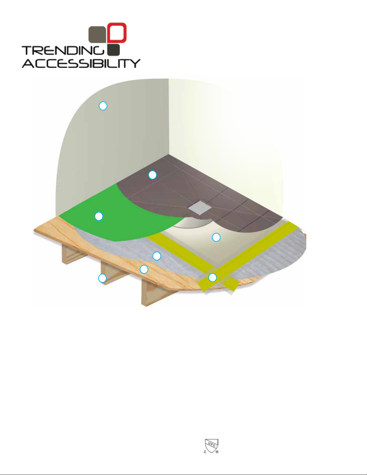
a) Wall
b) Tile
c) Shower Pan
a
b
d
c
d) Liquid Membrane
e) Crack Isolation Tape
f) Cement Board
g) Subfloor
h) Joists
f
g
h
e
adjustable fusion shower pan
on wood joists
installation guide
www.TrendingAccessibility.com
815 Hylton Road - Suite # 4
Pennsauken, New Jersey 08110
Phone: 856-488-9535 - Fax: 856-488-9576
2014/04/30Trending Accessibility
Page 2
b)
f)
Installation Guide
for adjustable fusion shower pan on wood joists
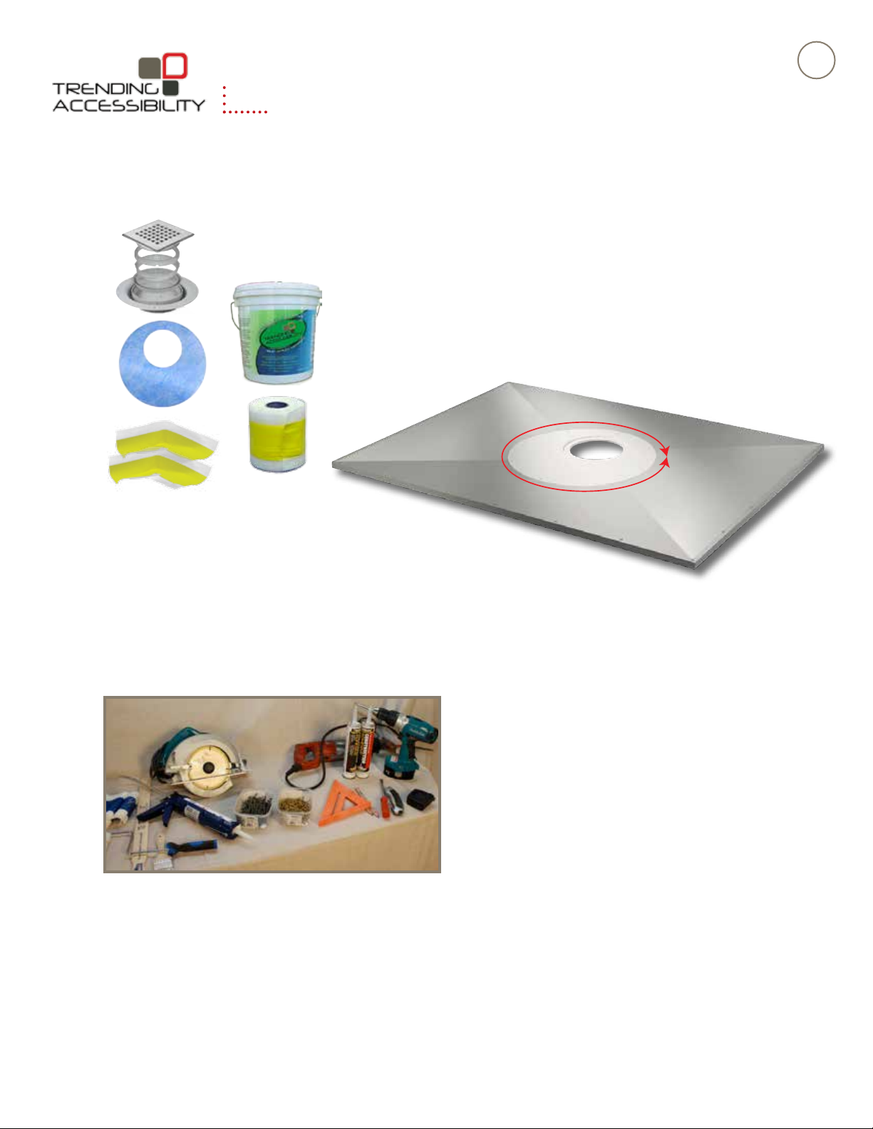
Required Components
a) Adjustable Fusion Shower Pan
b) Tile Drain
c) LiquidWaterproong
d) One Roll Rubberized Crack Isolation Tape
c)
e) 2 - Inside corners of Rubberized Crack Isolation Tape
f) Gasket Membrane
24 - 2 ½” screws
12 - ¾” screws
2
d)
e)
a)
Important: Do not install this kit without the appropriate
waterproof-membrane liners or coating.
Required Tools
• Drill
• Circular Saw
• Reciprocating Saw
• Level
• Square
• Caulk Gun
• Hammer
• Utility Knife or Scissors
• Tape Measure
• Paint Rollers
• Paint Brush
• Belt or Orbital Sander / Sandpaper
• Latex or Acrylic Caulk
• Solvent cement & primer
• Construction adhesive
• Splash Goggles
• Chemically resistant or impermeable gloves
t
n
e
m
t
s
ju
d
A
°
0
6
3
(DAP Dynaex 230
)
www.trendingaccessibility.com info@trendingaccessibility.com
Page 3
Installation Guide
for adjustable fusion shower pan on wood joists
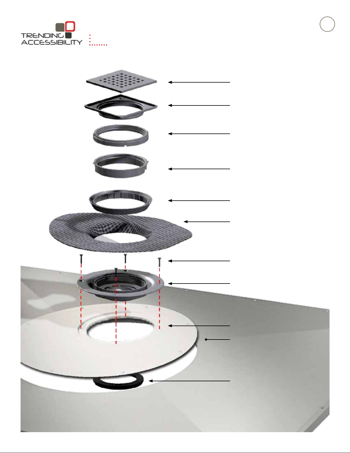
Stainless Steel Grate
Stainless Steel Drain Frame
Height Extension Ring (5/8” - 1”)
(Optional) - This must be fixed in place using
solvent cement.
Height Adjustment Ring (1/4” - 5/8”
rotate counter-clockwise to increase height - This must be
fixed in place using solvent cement.
3
Gasket Clamp (use solvent cement
on inner face to achieve seal)
Gasket Membrane
3/4” Screws
Drain Adapter Flange
Adjustable Rotating Center
Adjustable Fusion Pan
Sealing Washers
www.trendingaccessibility.com info@trendingaccessibility.com
Page 4
Installation Guide
for adjustable fusion shower pan on wood joists
4
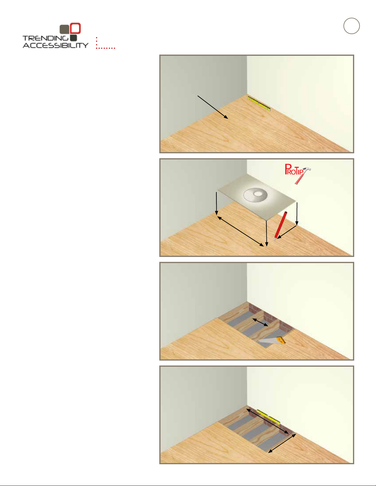
Step 1 > > > > > > > >
For optimal performance, it is imperative there is
a level surface prior to installation of new Fusion
pan. Check existing floor to make sure it is level. If
it is not, please correct prior to installation.
Step 2 > > > > > > > >
Place the Fusion pan in desired location and mark
the edge of the pan on the subfloor.
Note: If the Adjustable Fusion Pan needs to be
trimmed, follow the guidlines on page 12.
subfloor
If you need to cut the
pan to fit into a custom location, please
refer to the cutting
and drilling guidline
on page 12 for de
tailed directions
-
Step 3 > > > > > > > >
Carefully cut along your line as accurately as
possible. Make sure to adjust the depth of your
saw to the thickness of the subfloor as to not
cut through the joists. Note: If possible, please
check or mark location of existing plumbing and
electrical to avoid damaging them.
Joists must be 16”
on center
Step 4 > > > > > > > >
Remove the cut section of subfloor to expose the
joists.
www.trendingaccessibility.com info@trendingaccessibility.com
Page 5

Installation Guide
for adjustable fusion shower pan on wood joists
Step 5 > > > > > > > >
Install 2x stock to match existing joists, and block
around the perimeter of the Fusion Pan, around
the drain, and any unsupported edges of the
subfloor. This will ensure full support of Fusion
Pan, and existing subfloor.
Step 6 > > > > > > > >
5
2x Blocking
Place the Adjustable Shower Pan into place. Make
sure that pan is level and fits snugly into place.
Step 7 > > > > > > > >
We now want to make sure that the rotating
plate lines up with the waste line. First, Insert the
rotating plate onto the Adjustable Shower Pan. If
the drain position lands over a joist. Simple rotate
the plate until free of obstacles.
Step 8 > > > > > > > >
Once plate is set in the desired location, mark
the orientation on the plate and the pan. This will
ensure that you have the plate properly aligned
when you go to reinstall it later. While in place,
measure the location of the center of the drain.
Take four measurements, from the outer edges of
the pan to the center of the drain. You will need
these measurements to position the center of the
waste line.
www.trendingaccessibility.com info@trendingaccessibility.com
Mark the orientation of
the rotating plate
Page 6

Installation Guide
for adjustable fusion shower pan on wood joists
Step 9 > > > > > > > >
While the plumbing is exposed and accessible,
make all necessary connections to the waste line.
Use your measurements from the previous step
to make sure to position the waste pipe so that it
aligns with the drain hole.
Step 10 > > > > > > > >
6
For your dry run, position the Fusion Pan into place
and check to make sure the pan is level. If you
notice any rocking or flexing in the pan, you may
need to shim or shave areas.
Step 11 > > > > > > > >
IMPORTANT: You must sand the top of you pan
lightly with a palm or belt sander to roughen up the
surface for proper adhesion of waterproofing.
Make sure the sticker is completely removed.
Step 12 > > > > > > > >
To prep for permanent installation, remove the Fusion
Pan from the surface. Apply a generous amount of
construction adhesive to the joists and blocking.
www.trendingaccessibility.com info@trendingaccessibility.com
Page 7

Installation Guide
for adjustable fusion shower pan on wood joists
Step 13 > > > > > > > >
Carefully set the Fusion Pan into place. Using
the 2 ½” screws provided, attach the pan. Do not
aggressively screw and over tighten, as you may
force the Fusion Pan out of level.
Pre-drill the holes for the rotating plate. Now attach
the rotating plate using the ¾” screws provided. Be
sure to match up your tick marks done in step 8.
Refer to the Cutting and Drilling guidline on page 12
Step 14 > > > > > > > >
7
On top of existing subfloor install cement
backerboard in preparation for tiling. Make sure
that the top of the backerboard is roughly 1/8”
higher than the Fusion Pan.
Step 15 > > > > > > > >
Check that the Fusion Pan is level on all four sides.
Fill in any gaps around the perimeter of the pan over
1/8” with latex or acrylic caulk.
Recommended: DAP Dynaflex 230
Do not use 100% silicone.
Step 16 > > > > > > > >
Gasket Clamp
You now want to attach the Drain adapter flange
to the Fusion Pan.
First, set the adapter in place, mark the 4 holes,
and pre-drill them with a 1/8” bit.
Then apply a bead of caulk (
Dynaflex 230)
flange. Lightly push the flange into place, and
screw it down using the four ¾” screws provided.
Remove any excess caulk that squeezes out.
www.trendingaccessibility.com info@trendingaccessibility.com
to the underside of the drain adapter
Recommended: DAP
height adjustment ring
Adapter Drain Flange
membrane clamp
Remove the tile height adjustment ring and membrane clamp and
place to one side; these will be required later in the installation.
Page 8

Installation Guide
for adjustable fusion shower pan on wood joists
Step 17 > > > > > > > >
Make your final connections to the drain. First
apply a bead of caulk (
Dynaflex 230)
Pass the strainer through the drain adapter flange,
and tighten. Make sure connection is snug but do
not over tighten.
to the underside of the strainer body.
Step 18 > > > > > > > >
You will now begin waterproofing the wet room.
BEST PRACTICE: To achieve the best results, we
recommend waterproofing the whole room.
Recommended: DAP
8
Materials needed for wet room waterproofing.
Minimum requirements, shown in these
instructions, show you that you only have to
waterproof the shower zone, which is 6 ½ feet high
and about 2 feet outside of the showering area.
Step 19> > > > > > > >
Begin taping the wetroom floor at the interior corners
of the Fusion Pan using the corner pieces of the
crack isolation tape provided. Using a paint brush or
trowel, slather liquid waterproofing into corner, press
piece into place, then apply liquid waterproofing on
top. Make sure to smooth out any creases. Repeat for
additional corners.
Step 20 > > > > > > >
Using the 5” crack isolation tape provided, cut
strips of tape to length, to cover all seams (Corner
seams, wall/floor seams, pan/floor joint). Put
pieces aside.
If you are creating full wet room, you will need to tape
any seams throughout the entire room.
If you are only waterproofing the shower zone, you
will only need to tape the seams up to 2 feet outside
the shower area.
www.trendingaccessibility.com info@trendingaccessibility.com
Page 9

Installation Guide
for adjustable fusion shower pan on wood joists
9
Step 21 > > > > > > > >
Just like you applied the corner pieces, use your
cut strips of Crack Insulation Tape to cover all the
seams. Again, trowel or paint liquid waterproofing
onto seam, press tape into position and coat
the top to seal. Make sure to fully cover both
sides of the crack isolation tape with the liquid
waterproofing product. To make this process more
manageable, it is best to work in two foot sections.
Step 22 > > > > > > >
Using the 5” crack isolation tape. Overlap all seams
of cement board used on either the floors or walls.
Overlap the seam where the Fusion pan and cement
board meet.
NOTE:
Illustration just shows tape use.
Please apply liquid waterproofing to the wall and tape before
applying.
2 feet
Extend the tape
2 feet past the
shower pan
Make sure the tape
overlaps the seams
equally.
Step 23> > > > > > > >
Using the provided precut piece of gasket
membrane, slather area where gasket piece will
be adhered to the drain area. Place over drain
adapter flange, making sure to cover all screw
holes, and securely press down into flange. Coat
top of gasket piece with liquid waterproofing.
Important: Remember to remove the clamping
ring prior to placing drain gasket.
Step 24> > > > > > > >
Now attach the clamping ring. Apply primer and
solvent cement to inside of clamping ring. Press
firmly into position and allow the solvent to set.
It may take about 60 seconds for the cement to
form a bond.
NOTE: Do not allow the solvent cement to come
into contact with the membrane
Gasket Clamp
Drain Adapter Flange
Gasket
Membrane
Gasket Clamp
Drain Adapter Flange
Gasket Membrane
www.trendingaccessibility.com info@trendingaccessibility.com
Page 10

Installation Guide
for adjustable fusion shower pan on wood joists
Step 25> > > > > > > >
Continue the application of the liquid waterproofing
membrane. Paint a layer of liquid waterproofing
over all taped joints. It is easiest to begin with the
walls first and then proceed to the floor area. For
consistant application, use a paint roller to apply
waterproofing to all surfaces. Allow the waterproofing
to dry for about 4 hours. After first coat is dry, re-coat.
Step 26> > > > > > > >
Apply two coats of liquid waterproofing to achieve
40 mils. (roughly the thickness of a credit card)
10
Make sure that the “V” section of the gasket clamp
is filled with the liquid waterproofing.
Pro-Tip > > > > > > > >
To achive the best results, we recommend
waterproofing the whole room.
Step 27 > > > > > > >
In order to set the correct height of the grate frame,
you may need to use the height extension ring
(see diagram to the right). If the height extension
ring is required, it will need to be fixed to the height
adjustment ring using solvent cement. The grate
frame can now be attached to the height adjustment
or extension ring, depending on tile thickness. This is
done by using firm pressure to clip the components
together; it is a tight fit.
1/4” to 5/8” Tile Height
grate frame
adjusting ring
5/8” - 1” Tile Height
grate frame
extention ring
“click”
adjusting ring
www.trendingaccessibility.com info@trendingaccessibility.com
Page 11

Installation Guide
Standard drainage position
Drainage position 90° to the right Drainage position 90° to the left
cannot rotate the drainage point a full 90°,
r right, it is best to use smaller tiles
mum size 2.75” square) or mosaic tiles.
for adjustable fusion shower pan on wood joists
Step 28 > > > > > > >
The height adjustment ring and floor drain bowl
must now be fixed together using solvent cement.
Because solvent cements sets very rapidly we
strongly recommend the adjustment is done “dry”
first.
To set the permanent height of the grate frame,
place a floor tile beside the frame. Rotate the frame
until the height is about 1/16” higher (this accounts
for adhesive thickness). Now mark the position
of the adjustment ring. This mark shows the
final height position. Remove ring, apply solvent
cement, and re-align components to your marked
position. It is best to hold securely until pieces are
fully bonded.
Step 29 > > > > > > >
11
The metal grate frame can be rotated to match the
direction of the tile.
You are now ready to tile. If you are using large
format tiles, they must be cut diagonally and laid
to follow the pitch in the Fusion Pan (From the
corners of the grate frame to the corners of the
Fusion Pan). Use Tiling Guide below.
Apply the tile adhesive, and lay the tiles in a regular
pattern.
Step 30 > > > > > > >
Once your tiling is complete, grout the floors and
walls. Finalize by adding the drain grate. It is a
friction fit and must be pressed all of the way in.
Your Fusion Pan installation is now complete.
Enjoy!
Tiling Guide
Standard drainage position
www.trendingaccessibility.com info@trendingaccessibility.com
Drainage position 90° to the right Drainage position 90° to the left
Drainage position less than 90° to the right
If you
If you cannot rotate
left o
the drainage point
(maxi
a full 90ଂ, left or
right, it is best to
use smaller tiles
(maximum size
2.75” square) or
mosaic tiles.
Page 12

Installation Guide
Adjustable Fusion Shower Pan - Cutting and Drilling guideline
for adjustable fusion shower pan on wood joists
Cutting and Drilling Guidlines
Do not cut into central
Fig .1
Cu t usi ng an o ld o r d i sposab l e hand s aw.
solid oval section
Max imum cut
Ma x imum cut
12
Ma x imu m cut
Max imum cut
Additional timber
Fig .2
Cu t t o l en gt h.
Ens u re a ll the c u t e dges ar e sup por ted, t hen dr i ll, coun t ers i nk and screw the Pan to t he j o ist s be l ow in a round 7.87”
int e rva l s ( a v oid i ng pi pes , e l e ct r ic w ires , et c .).
Import ant: Do not cu t the edges that adj o i n s u rroun d ing f l oor. Cutt ing the Pan m ay reduce flo w ra t e pe rf orm anc e.
Fig .3
Cut to a ccommo da te d ia go na l w al l .
Additional timber
Additional timber
Fig .4
Cut to acc ommod at e d ra in p oi nt .
Fig .5
Ensur e cut ed ge s a re fi xed.
Additional fixing points
Additional drilled and
countersunk screws
required if Pan is not
in contact with joists/
concrete floor.
Fig . 6
If Pan is not in contac t wit h joi s t/c onc ret e floo r y ou mus t dr i ll out
and count e rs i nk t he Pan to ensur e it does. Fail u re to do t h is w ill all o w
unaccept able m o v ement a nd m a y c aus e f l oor ti l es t o cra ck or b eco m e loos e .
www.trendingaccessibility.com info@trendingaccessibility.com
 Loading...