

Page 1

READ ALL INSTRUCTIONS BEFORE INSTALLATION
PLANNING YOUR INSTALLATION
MULTI-PIECE SECTIONAL PRODUCT
INSTALLATION INSTRUCTIONS
Avoid exposure to weather. Product cartons are not waterproof. Cartons exposed to rain or snow may
result in accumulated water penetrating the back laminates of the shower and soak the glassed in
reinforcement supports causing bulges in the gelcoat surface.
1.
Most handling damage is the result of impact blows to the back of the fiberglass units.
2.
Never drag sectional parts of this fiberglass product on any surface. Always carry the parts or use a two
wheel dolly.
3.
Never drop these fiberglass parts from any height, not even an inch or stress cracks are likely to occur.
4.
Placing objects inside the unit can cause scratches or nicks to the finished surface.
Do not use the shower as a trash receptical! Always place a drop cloth or cardboard on the floor when
working inside the shower.
5.
Never clean fiberglass gelcoat surface with metal tools of any kind, including razor blades.
6.
TOOLS NEEDED:
Nails
1/8” Drill Bit
Hammer
Drill With Phillips Screw Bit
1/2” Notched Trowel
Spatula
Grease Pencil (China Marker)
Auger Mixing Tool For Drill
Caulking Gun
4 Foot Level
2 Foot Level
50+ 1 1/4” Wood or Flat Head Screws
Solid Wood Flooring Adhesive
(2-One Gallon Buckets Per Shower)
(For Mixing Bedding Compound And Water Test Around Drain)
2-Gallons Of Water
1-Tube White Bathroom Caulking
2-Tubes 100% Clear Silicone Caulking
3 - 8 Foot 2 x 4’s
1 - 8 Inch Long 2 x 4
1 - 24 Inch Long 2 x 4
2 - Large Wiping Cloths
Self-Caulking Shower Drain Fitting
MATERIALS NEEDED:
1
856-488-9535 www.TrendingAccessibility.com
Page 2

PLANNING YOUR INSTALLATION
5.
In the installation location, the drain opening in the floor should have a 6” core for the drain pipe, and a
10” x 10” x 1/2” deep recess in the sub floor. (The drain core must be blocked when filled with
Thin-Set). The 10” x 10” x 1/2” deep recess is required to to assure proper drainage.
(See “Detail Of Drain Core Area” on Page 3).
4.
Plan for the location of the shower water control valve. Note if planning to install the control valve in the
back wall of the shower with a two piece back wall, consider the location of the seam in the wall.
The control valve must be located at a height where the seam and mounting flange do not cause a
conflict with placement of the control valve, or water supply lines. These considerations are not necessary
if installing on the one piece back wall, or side wall.
Plan for routing the water supply lines to the control valve installation location.
The 2 wall Framing Diagram is for the 6060 3P two wall shower only.
BRIEF OVERVIEW. The actual installation will begin on the next page.
2
Review the Framing Diagrams in Figure 1. Modify existing framing if required. For new construction, build
framing structure in accordance with product dimensions and notes shown in the Framing Diagrams.
1.
Following the shower pan installation, place the back wall sections, then the side walls. The parts are
indexed to one another by a slot and pin connection system. The parts are pushed tight together before
connection to the framing pocket is made.
To have a successful installation, two persons are required.
3.
The shower base will be installed, leveled, and fastened to the framing before the walls are installed.
It is essential the framing pocket be square and plumb for the unit to install properly. The floor also must
have no voids or out of level conditions. If these are present, they must be corrected before installation.
Floor leveling compound can be purchased at Lowes or The Home Depot.
2.
Note: Unit will not install properly if framing pocket is not square and of proper size.
The dimensions shown in the FRAMING DIAGRAMS are 1/4” larger than the size of the shower.
This product is manufactured to tight specifications. The 1/4” over sizing is for maneuvering and
installation ease. If 1/4” over is not reasonable, sizing closer to the product actual dimensions is
allowable.
When trial fitting the shower, use a level to confirm the parts are level and plumb. If any gaps are
present between the shower and framing, use furring strips to fill the gaps. If the walls and floor
are not level, there may be an excessive gap at the seams. The unit is designed to allow an 1/8”
gap at the seams.
7.
Locate accessories if any were ordered. They will be packaged in the pan box. Remove those and store
them in a safe location for easy retrieval.
8.
Identify each package and its contents. The label on the box is clearly marked indicating a shower pan
and wall panels.
Check the outside of the package for visible shipping damage. If damage is noted, contact your supplier
before proceeding with the installation.
6.
Page 3
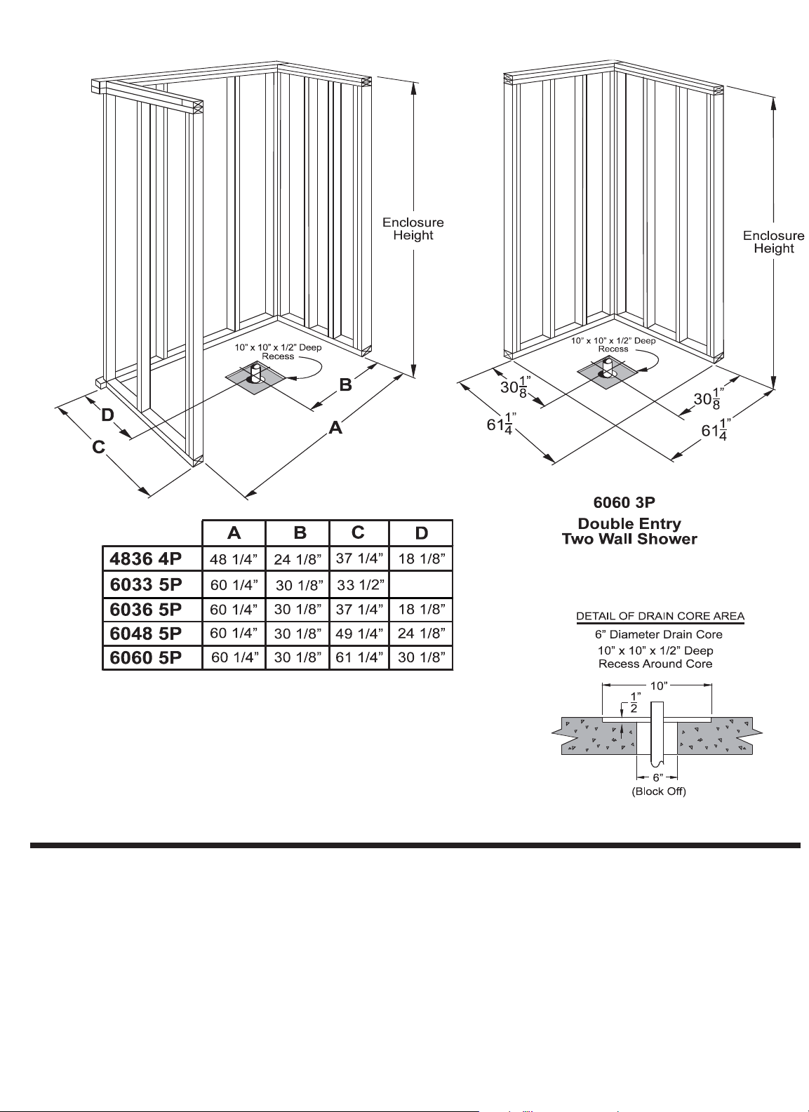
Framing pocket must be sized according to the information provided in the Framing Diagram.
It is recommended that the front studs at each side be doubled for added strength. Framing must be
extremely square and plumb in order to accomplish a successful installation.
2.
It is extremely important that the floor area intended for the installation be flat and level. Any areas over
1/8” out-of-level will prevent the installation from being successful. If an area out more than 1/8” is found,
float the floor area with a floor leveling compound. This material must be placed and cured (dry) before
proceeding with the shower installation.
4.
1.
Prepare the installation area by sweeping the area completely clean
3.
Install hot and cold water supply lines with the control valve. Mount to the framing.
Note: Unit will not install properly if framing pocket is not
square and of proper size. The dimensions shown in the
FRAMING DIAGRAMS are 1/4” larger than the size of the
shower. This product is manufactured to tight specifications.
The 1/4” over sizing is for maneuvering and installation ease.
If 1/4” over is not reasonable, sizing closer to the product
actual dimensions is allowable.
INSTALLATION INSTRUCTIONS
3
FRAMING DIAGRAMS
Figure 1
15 3/8”
Page 4
6.
Carefully measure the framing pocket to assure it is of
proper size for the unit to be installed. Refer to
dimensional information in the Framing Diagrams on
Page 3, Figure 1.
5.
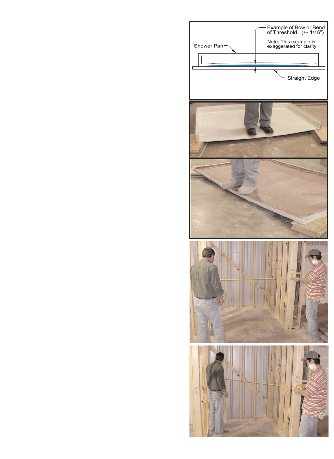
A special note: During handling and transport,
the product may be slightly bent. It is very important
that the seam side of each wall, and the threshold of the
pan does not have any bow or bend. This product is
engineered with materials that allow for the sections to be
pressed back to the normal and straight factory form that
is intended.
7.
Check the framing pocket for square. Check to assure
the vertical studs are plumb. To have tight seams where
the parts meet, it is very important that the framing pocket
be exceptionally square and plumb.
Check for square by holding a measuring tape from the
back left corner to the front right corner, as shown in
Figure 4. Repeat for the other side. If both dimensions are
the same, the framing is square. Adjust if necessary.
As each section is removed from the packaging, use a
straight edge to check the straightness of the wall sections
and of the threshold. An example of checking the threshold
is illustrated in Figure 2A. Check all the parts, and if not
straight, follow the procedures outlined below to bring the
parts back into the intended condition.
In the event they are not straight to 1/16”, pressure can be
applied to the top side of the material. This can be
accomplished by placing blocks under the two extreme
corners.
Always place a soft rag on the finished surface where it
contacts the wood blocks, and under your feet to avoid
damaging the finish.
Gently step on this area and allow your body weight
(Up to 250 pounds), to flex the material back straight.
Confirm straightness, repeat if necessary until +/- 1/16”
is accomplished. (Figures 2B and 2C)
Once the dry fit has been done and the fit confirmed,
disassemble the components. Resume step 5 and follow
each step carefully.
A complete dry fit for the shower base and walls is
recommended. A dry fit in this instance is defined as
securing the sections to the studs with no silicone and
minimal screws to confirm a good fit, and the framing
accommodates the sections. To achieve a dry fit
installation, proceed with steps 6 through 23 without using
the silicone, floor adhesive and minimal screws to secure
to the framework.
4
Figure 3
Figure 4
Figure 2C
Figure 2B
Figure 2A
Page 5
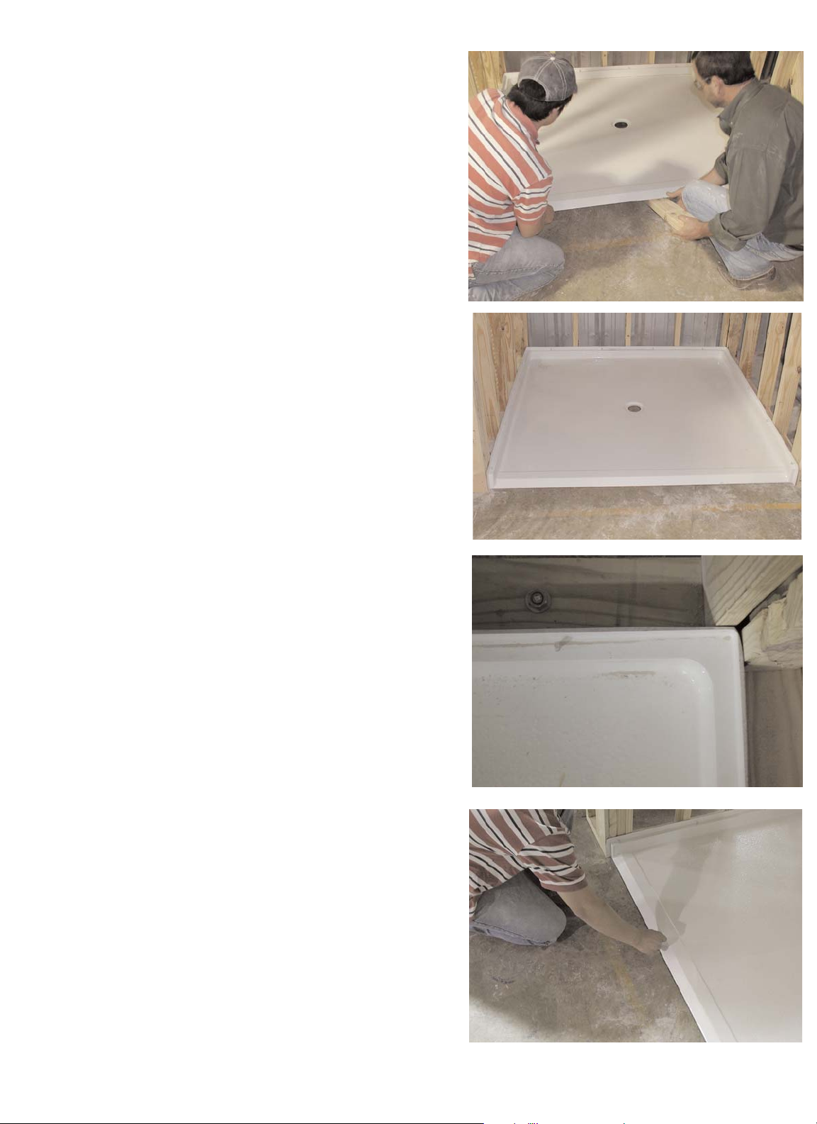
9.
Once the shower pan is put into place and
fit is confirmed, draw a pencil line on the sub floor
indicating the front point of the threshold of the pan.
(See Figure 8).
The back corners of the shower pan should be in
contact with the framing, as seen in Figure 7.
Shim these areas if required.
Place a piece of cardboard in the floor of the shower to
protect the floor during the additional steps of installation.
There is a cut out for this on the pan box.
5
After the pan is set, fill any gaps between the mounting
flange and the framing with wood shims or furring strips to
achieve solid contact. The flange must be in contact with
the studs along all sides.
Figure 7
Figure 8
Figure 5
Figure 6
8.
The next step is to dry fit the shower pan to the studs
and confirm the drain location.
The better fit of the pan, the better all wall parts will
assemble as intended with minimal gaps at the seams.
Note in Figure 5 the two installers have placed the shower
pan on the floor, and are pushing it into the installed
position. One of the installers is using a short piece of 2 x
4 wood to hold the front of the shower pan off the floor.
This will assist in moving the pan into the installed position
while preventing chipping the front edge if it were to slide
along the sub floor.
Page 6

12.
The next step is to permanently install the
shower pan. A helpful tip to make this easier is to
rotate the pan upward and lean against the back framing
studs of the pocket. This will remove the pan from the
work zone without removing it from the stud pocket. Do
not secure the pan to the studs at this point because you
may need to reach around the pan as you install the
drain fitting detailed in the next step. Make sure pan is
angled enough so it will not fall.
6
Figure 11
10.
Confirm the pan is level by using a long level on
top of the threshold, and along the sides and back.
Note the level is used on the same horizontal surface that
has the pins.This will be important to allow the wall panels
to fit correctly. (See Figures 9A and 9B).
11.
Drill holes through the mounting flanges into each
framing stud. These holes should be drilled using a
1/8” drill bit. (See Figure 10).
Note: Plan on using flat or pan head screws to secure the
shower pan. An 1/8” gap is provided in the shower design
to account for the screw heads. This gap will allow
clearance so the walls may assembled to the shower pan.
Wipe away any excess caulking that may have squeezed
out on the inside of the pan.
If the pan is not level, shim the appropriate areas
to achieve level. Do not shim more than 1/8”. If
shimming over 1/8” is required, remove the pan
and correct the sub-floor area by
“floating” a floor leveling compound.
Figure 10
Figure 9B
Figure 9A
13.
Install the drain fitting on the shower pan.
Apply a bead of 100% silicone caulking around
the recessed molded drain area on the finished side of
the pan. Remove the nut and all gaskets from the drain
body. Slip the threaded shank of the drain body through
the hole. Follow the instructions provided with the drain
fitting to install the gaskets in the proper location. When
all gaskets and locknut are in place on the bottom side
of the shower, tighten the nut to secure the shower drain
assembly. From the top side of the drain assembly,
remove the rubber caulking gasket located on the inside
of the drain fitting. This will allow the drain pipe to slip
through the drain fitting on the shower.
A diagram of a typical drain assembly is shown on
Page 14 of this manual.
Page 7

Non shrink thin-set mortar can be purchased at Lowes or
The Home Depot. Please follow the mixing directions on the
bag.
In this step, apply the adhesive to the flat floor area and fill
the boxed area around the drain pipe with the Thin-Set
mortar.
After the adhesive is troweled over the sub floor, use a
spatula to wipe the adhesive over the entire area where the
pan will sit.
The exception will be the drain box area. This area will be
filled with thin-set non shrink mortar. Do not fill this area
above the floor line and do not spill any of this thin-set
material onto the contact adhesive.
(See Figure 13B.)
7
14.
A solid wood floor adhesive will be used to “glue” the
bottom side of the shower pan to the sub floor.
The following steps will detail the appropriate steps to
accomplish this.
15.
Clean the sub-floor thoroughly, wiping away all lose debris.
Wipe up any moisture. Never use adhesive on a dirty or
damp surface.
16.
Now secure the pan in the upright position to the back framing.
Use a piece of scrap 2 x 4 lumber to temporarily secure it. See
the example in Figure 12.
Figure 12
To secure the shower pan to the floor a solid wood
floor adhesive must be applied to the entire sub
floor area where the shower pan will rest.
Using a 1/2” notched trowel, apply adhesive evenly over the
pan contact area. Bring the adhesive up to the threshold
pencil mark and also make sure the adhesive will be in
contact with the back side of the pan. The long edge of the
trowel may be needed to get the adhesive to the far back of
the contact area where the pan is resting against the framing
studs in a vertical position.
(Pan not shown in Figures 13 A and B).
Figure 13A
Figure 13B
Page 8

17.
After the adhesive and thin-set materials are in place, rotate
the pan back into place for installation.
(Hint) In order to reach the pan without stepping on the adhesive,
place a short piece of wood over the drain area. Use this to step
on to remove the 2 x 4 that is holding the pan against the back
framing. (See Figure 15).
18.
19.
Before installing the walls, confirm the ledges
where the walls sit are level. Check with a long
level as shown in Figure 16. If there is an out of level
condition, remove screws and adjust as required.
Before the adhesive cures, confirm the floor slope to the
drain has been maintained. To do this, use a 2 foot level at
various points around the drain to the adjacent wall to check
for draft. Make sure there is a downward slope to the drain in
all directions around the drain. Visually inspect the floor to be
sure there are no humps or dips that could cause improper
drainage.
See Figure 17A and 17B.
Rotate the pan back to the horizontal position. As you lower the
pan to the sub floor, align the drain pipe with the drain fitting,
and with the pencil mark at the front of the threshold.
NOTE: The working life of the flooring adhesive is roughly
one hour. (Refer to the label on the adhesive for actual
working time). After step 16 is complete, the entire
installation process though step 23 must continue. If for
any reason the installation cannot be completed within the
working time of the adhesive, after step 16, jump ahead to
step 23.
When the pan is seated into the adhesive, place the cardboard
on the shower floor for protection. Thoroughly walk around in
the shower. This will assist in seating the pan into the adhesive.
Attach the pan to the studs by installing the flat top/pan
head screws through the holes drilled into the flange.
Snug the screws up tight so the screw heads will be clear
of the side wall panels for assembly. Use care not to
overtighten to the point that causes flange breakage.
Figure 16
8
Figure 17B
Figure 17A
2 Ft. Level
Floor Level To
Drain - No Humps
Figure 15
Wood
Page 9

21.
If all fits are good, proceed with the installation of the
the back wall. The installation procedures described in this
step apply for installation of one or two piece back walls.
Wipe clean the ledges on top of the pan. Apply a continuous
bead of 100% RTV silicone caulking along the back ledge of the
pan where the back wall will sit. The bead should be placed at
the middle of the ledge, and be 3/8” wide. The bead should go
completely around each alignment pin.
The lower section of the back wall is the panel with a single,
molded soap dish. Lift this panel up and carefully lower it onto the
back ledge on the pan.
There are slots on the underside of the wall. There are alignment
pins in the pan that will insert into the slots on the bottom of the
wall. See the detail in Figure 19.
Pre-drill the mounting flanges. Attach the wall with screws
through the back wall flange into the framing. Be sure the wall
panel remain level and plumb. (For the 4836 4 piece, this step
will apply for the entire back wall as one piece).
Push the wall panel down to seat it in the caulking.
Check the fit for level and plumb.
Note to installer: There is a difference having the bubble
between the lines and a plumb wall. The wall must be
VERY plumb or a gap larger than 1/8” will be present
where the side walls mate the back wall. Use wood shims
or furring strips to fill any space between the back wall
flange and the studs.
Align the wall section where it meets the shower pan so it is
centered on the pan, and install wood shims or furring strips
if necessary.
9
20.
The next step will be to place the wall panels on the pan.
The back wall will be installed first. If the water control valve
is in the back wall, carefully measure and mark the location on
the surface of the wall panel. If installing in a shower with a two
piece back wall, the valve probably will be installed through the
lower wall panel. Make certain the valve does not conflict with
the mounting flange or seam. Read the installation instructions
provided by the valve manufacturer. Before the Trial fit, carefully
drill the valve hole (s) in the panel. When drilled,dry Trial fit the
back wall panel (s) on the shower pan to test the fit.
Confirm the gap where the wall seats to the pan is 1/8” or less.
Make sure the seam for the two piece wall is also 1/8” or less.
Adjust the valve hole size and location if required.
Lift the wall panel with the valve hole away. Complete the valve
installation and connection to hot and cold water supply at this
time. Also complete shower supply connection. Strap pipes to
framing if required. This is the last access to the plumbing before
the wall is permanently installed.
Figure 18
Figure 20
Figure 21
Figure 22
Figure 19
Pin
Slot
Page 10

22.
For 5 piece units, the next step is to place the top section of
the back wall. Clean the back ledge and apply a continuous
bead of 100% RTV silicone caulking along the ledge of the back
wall where the top part of the wall will sit. The bead should be
3/8 wide and placed at the middle of the ledge. It should go
completely around each alignment pin.
If the water control valve is located on one of the side walls, it is
important to dry trial fit that panel first. Carefully measure and
mark the location of the valve on the surface of the side wall.
Read the installation instructions provided by the valve
manufacturer. Carefully drill the valve hole (s).
23.
Side wall installation. The side wall panels are slotted on the
bottom. The alignment pins in the pan will index with these
slots. The slots will allow the side wall panel to slide about one
inch to meet the back wall panel.
Trial fit the side wall panel to the shower pan. Wipe clean the
side ledge. This next step is a two person job.
Lift the side wall panel and set it on the ledge. Set the panel so
it is within one inch of the vertical back wall seam. Make sure
the pins in the pan index with the slots on the bottom of the wall.
Clear your fingers and slide the wall panel toward the back wall.
Make sure the alignment pins in the back wall index into the
holes on the side wall. (See Figure 24)
Lift the top back wall panel and set it on top of the lower wall.
Press the panel down to seat in the caulking. The top and
bottom wall panels must be level and plumb. Shim if necessary.
The seam between the panels should be no more than 1/8”.
Pre-drill holes and attach with screws along the top back flange
into the framing studs. Make sure the two wall panels are in
alignment and are level and plumb. Place level or straight edge
on both vertical flange where the wall will mate to the back wall
and check to assure there are no gaps. (For the 4836 4 piece
which has a single piece back wall panel, skip this step).
Figure 22
Figure 23
Figure 24
Figure 25
10
When seated, the seam should have a minimal gap of 1/8” or
less. If not, push the end of the side panel until the vertical
seam closes. (See Figure 25) When in place, check the fit of
the valve hole. Adjust size and location if required.
Clean the side ledge and apply a continuous 3/8” bead of
100% RTV silicone caulking along the entire length of the
mating ledge of the shower pan. Apply the caulk completely
around each alignment pin.
When the fit is good, lift the wall panel away.
Complete the valve installation and connection to hot and cold
water supply at this time. Also complete shower supply
connection. Strap pipes to framing if required. This is the last
access to the plumbing before the wall is permanently installed.
Page 11

11
24.
Now that all wall panels are installed, remove the
protective cardboard from the floor and use a 2 foot level
to re-check the downward floor draft to the drain. Use the
same procedure as described in Step 18 of this manual.
Since there is minimal floor slope to the drain, it is
critical factory slope be maintained so the shower drains
well. To accomplish this, temporary bracing must be put in
place to assure the floor remains in the proper position as
the adhesive cures.
Before installing the bracing, place a padded piece of wood
on the top center of the threshold and directly on top of the
drain. Pad the wood with soft cloth or cardboard to prevent
damage to the finish.
Install temporary 2 x 4 stud bracing so they sit on top of
these wood pieces. Attach these studs to the room framing
above the shower, or pad to the ceiling. (See Figure 26).
Figure 26
26.
Remove the temporary bracing after 72 hours. Place a
piece of cardboard in the shower to protect the finish.
Caulk all seams with white acrylic bathtub caulk.
Confirm fit and level. Inspect that the grout lines on the side
wall match up with the grout lines on the back wall.
Using a grease pencil or china marker to make a short line
across the grout lines makes it easier to see if the grout lines
are in alignment.
Pre-drill mounting flanges and attach to framing studs
with screws. Make sure wall panel remains level and plumb
and the seam is tight.
Repeat the procedures in Step 22 for opposite side wall.
Lift the side wall and place it on the pan. Make sure alignment
pins on the pan and back wall line up. Clear fingers and slide
the wall into the installed position. (See Figure 25)
Clean and apply a continuous 3/8” bead of 100% RTV silicone caulk along the entire length of the vertical surface of
the back wall where the side wall panel mates to the back
wall. Apply the caulk completely around each alignment pin.
(See Figure 23).
25.
Install the rubber caulking gasket around the drain pipe.
Trim the length of the pipe if necessary. Apply soap to the
caulking gasket to lubricate it. Place the caulking gasket on
the drain pipe and press it down into the drain assembly until
it seats. Snap the strainer plate onto the drain.
Pour water across the floor to confirm good draft to the
drain so the water drains completely with no puddling.
Make certain the drain does not leak.
Note: The manufacturer and supplier of this product is not
responsible for leaking drain conditions. Proper installation
of the drain fitting and pipe is the installers responsibility.
Page 12

Materials Required:
Acrylic Latex Caulk
Wiping Cloths (Rags)
Clean Water
Cut off tip of caulk tube diagonally with opening
no larger than 1/8”.
(Figure 27)
Run a continuous bead of caulk at the seam between
the two parts.
(Figure 28)
Smooth caulk gently with a wet fingertip. (Figure 29)
Using a clean rag, wipe off excess water and caulk.
(Figure 30)
12
Seam Caulking Instructions
Figure 27
Figure 28
Figure 30
Figure 29
Tools Required:
Caulking Gun
Cup
Your seat with swing down legs is fully assembled. Remove it from the box and proceed as follows:
(This style seat has four (4) adjustable height legs)
1.- Choose the height of the seat you want. Barrier Free style showers will typically have fold up
seat installed at 17” to 19” height.
2.- After selecting the height you desire, adjust each of the four legs to that height while
maintaining the seat in a level position. Lock each of the lock nuts.
3.- Place the seat against the wall of the shower where you want the seat to be located.
Seat may be centered on the wall for a Barrier Free installation.
INSTALLATION INSTRUCTIONS FOR SHOWER SEATS
WITH SWING DOWN ADJUSTABLE LEGS
4.- With the seat placed against the mounting wall, position the two hinges to the wall.
Using a pencil, mark the three holes (3) holes in the flange onto the wall for each hinge.
Remove seat from wall.
Page 13

13
5.- Using a power drill with a 0.120 diameter drill through the wall the three (3) mounting
holes for each flange.
Recommended tools for installation:
THIS COMPLETES THE INSTALLATION OF THE SEAT
7.- Place the seat against the mounting wall with each hinge aligned to the mounting holes.
Utilizing the six (6) #10 x 2” Stainless Steel screws, place a Phillips screw driver into
your power drill and securely tighten each of the six (6) screws.
1/4” Power Drill
#2 Phillips Screw Driver and/or Phillips drill insert
1/2” Open end wrench or a small Crescent wrench
1/8” Diameter drill bit
Tape measure
Pencil/pen
Silicone Caulk
INSTALLATION INSTRUCTIONS FOR SHOWER SEATS Con’t:
1.- Select the particular size and style of grab bar you want to install. Certain grab bars
have snap in place flange covers, and others have exposed flanges.
2.- For grab bars with snap in place flange covers, use the handle of a Phillips screw
driver to tap back the covers on the bottom edge of the covers. It will be convenient in
the installation process if the covers are tapped together in the center of the grab bar.
3.- Determine the position you want the to install the bar. Place the bar against the wall.
Using a pencil, mark the location of each mounting hole at both ends of the bar.
4.- Using a power drill with a 1/8” diameter drill bit, drill, each mounting hole at a depth of
approximately one (1) inch.
Recommended tools for installation:
THIS COMPLETES THE INSTALLATION OF THE GRAB BAR
6.- Take two (2) of the #10 x 2” Stainless Steel screws. By hand, start one mounting screw
in each end of the bar into the wall.
7.- Use a power drill with a Phillips drill bit to fully install these mounting screws.
8.- Take the remaining #10 x 2” screws and place them into the remaining open holes.
Use care to snug up the screws, but to not over-torque that the screws strip out the
factory installed backer board.
9.- If installing a bar with snap-on covers, move the covers into place at each flange.
Twist the covers clockwise or counter clockwise to tighten the covers onto the flanges.
1/4” Power Drill
#2 Phillips Screw Driver and/or Phillips drill insert
1/8” drill bit
Tape measure
Pencil/pen
Silicone Caulk
INSTALLATION INSTRUCTIONS FOR GRAB BARS
5.- Apply silicone caulking around and inside each drilled hole before installing the grab bar.
6.- Apply silicone caulking around and inside each drilled hole before installing the seat.
Page 14

14
Revised: 2-3-11
 Loading...