

Page 1
Form 080/01
Complimentary Reference Material
This PDF has been made available as a complimentary service for you to assist in
evaluating this model for your testing requirements.
TMG offers a wide range of test equipment solutions, from renting short to long
term, buying refurbished and purchasing new. Financing options, such as
Financial Rental, and Leasing are also available on application.
TMG will assist if you are unsure whether this model will suit your requirements.
Call TMG if you need to organise repair and/or calibrate your unit.
If you click on the “Click-to-Call” logo below, you can all us for FREE!
TMG Corporate Website TMG Products Website
Disclaimer:
All trademarks appearing within this PDF are trademarks of their respective owners.
Page 2

Page 3
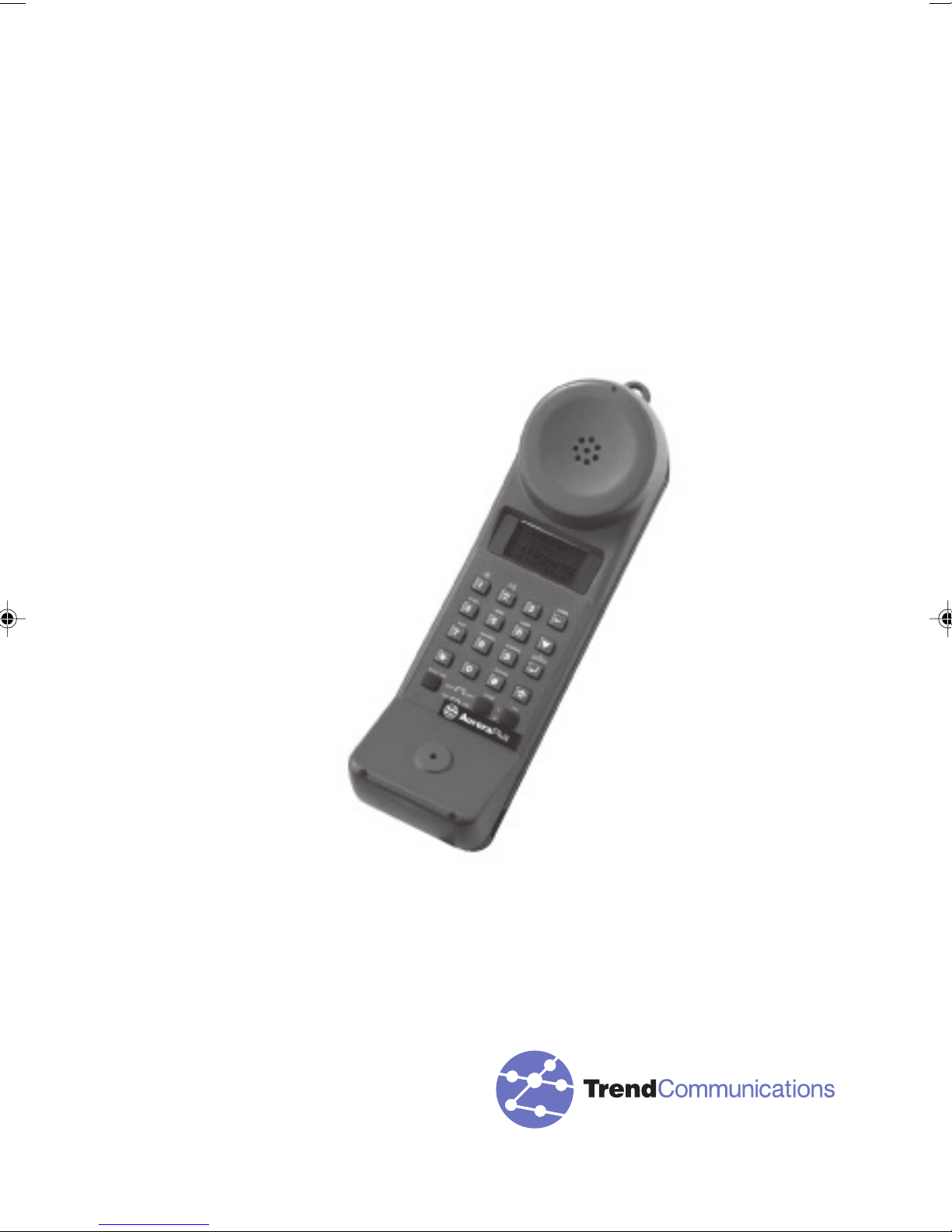
Trend AuroraPlus
User Guide
429850
Issue 5 - 04/01
Page 4

Trend AuroraPlus User Guide
429850
Page 5

Copyright Notice
The information contained in this document is the property
of Trend Communications Ltd. and is supplied without
liability for errors and omissions.
No part of this document may be reproduced or used except
as authorised by contract or other written permission from
Trend Communications Ltd. The copyright and all
restrictions on reproduction and use apply to all media in
which this information may be placed.
Trend Communications Ltd. pursue a policy of continual
product improvement and reserve the right to alter without
notice the specification, design, price or conditions of supply
of any product or service.
The Trend Aurora name is a registered trademark of Trend
Communications Limited.
Windows is the registered trademark of Microsoft
Corporation.
© Trend Communications Ltd. 2001
All rights reserved
Publication ref: 429850
Issue 5 - 04/01
Trend Communications Ltd.
Knaves Beech Estate,
Loudwater,
High Wycombe,
Buckinghamshire,
HP10 9QZ
U.K.
TEL: +44 (0) 1628 524977
Issue 5 - 04/01 i
FAX: + 44 (0) 1628 810094
email: [email protected]
Page 6

Trend AuroraPlus User Guide
International Contact Addresses
Trend Communications S.A.
Burospace - Bât 7
Route de Gisy
91571 BIEVRES CEDEX
FRANCE
TEL: + 33 1 69 35 54 70
FAX: + 33 1 60 19 00 48
Trend CommunicationsGmbH
Valerystr. 1
85716 Unterschleißheim b. München
GERMANY
TEL: + 49 89 32 30 09 (0)
FAX: + 49 89 32 30 09-99
Trend Communications SRL.
v. Cavriana 3
20134 Milano
ITALY
TEL: + 39 02 7391.414
FAX: + 39 02 7391.309
Trend Communications s.l.
Pujades, 60
08005 Barcelona
SPAIN
TEL: + 34 93 300 3313
FAX: + 34 93 309 2385
ii 429850
Page 7

Trend Communications
C-207 Twin Arcade
Military Road
Marol Andheri (East)
Mumbai 400059
INDIA
TEL: + 91 228 597463
FAX: + 91 228 596155
Help Desk Numbers
If you have any queries about the operation of
AuroraPlus, you can contact the Trend Communi-
cations Ltd. Help Desk:
From within the UK: 08457 660 854 (local rate)
From France: (1) 69 35 54 75
From Germany: (0) 89-32 30 09-44
From other non-UK countries: +44 1628 851085
For sales enquiries, talk to your local Trend
Communications representative.
Web Site Information
www.trendcomms.com
Issue 5 - 04/01 iii
Page 8

Trend AuroraPlus User Guide
iv 429850
Page 9

Contents
Contents
Introducing AuroraPlus ............................................. 1-1
Welcome ! ........................................................................ 1-1
Conventions in the Guide .................................................. 1-2
Your AuroraPlus ................................................................ 1-4
Types of AuroraPlus........................................................... 1-4
Features ............................................................................. 1-4
Use ................................................................................... 1-7
Supplied with AuroraPlus ................................................. 1-8
Looking after AuroraPlus .................................................. 1-8
Safety Advice ................................................................... 1-8
Where to get more information ........................................ 1-9
ISDN Explained .............................................................. 1-10
What is the ISDN? ............................................................ 1-10
ISDN Services .................................................................. 1-10
Equipment on the ISDN ................................................... 1-11
ISDN Interfaces ................................................................ 1-11
ISDN Standards ............................................................... 1-12
Pulse Code Modulation ................................................... 1-12
Methods of Voice Encoding ............................................. 1-12
Line Coding Techniques ................................................. 1-13
Basic Rate & Primary Rate ISDN ..................................... 1-13
The OSI 7-Layer Model .................................................... 1-15
Layer 1 (BRI) .................................................................... 1-16
Layer 2 .............................................................................. 1-17
Layer 3 .............................................................................. 1-17
Protocols .......................................................................... 1-18
Getting Started .......................................................... 2-1
A Look at AuroraPlus ....................................................... 2-2
The Keypad ...................................................................... 2-3
Switches ........................................................................... 2-4
S/U Change-Over Switch .................................................. 2-4
POTS Check Switch (Only via U Access Cable) .............. 2-5
Battery Charging Switch (Optional) .................................. 2-6
Termination Resistor Switch (TERM) ................................ 2-6
Interface Switch (Optional) ................................................ 2-7
Communication Ports & Connectors ................................ 2-8
Connecting AuroraPlus ..................................................... 2-9
Switching Power On ....................................................... 2-11
Issue 5 - 04/01 v
Page 10

Trend AuroraPlus User Guide
Displaying the Main Menu .............................................. 2-12
Scrolling through Menu Pages ....................................... 2-12
Selecting Menu Options ................................................. 2-13
Exiting from a Menu ......................................................... 2-14
Returning to the Main Menu ............................................ 2-14
Using Hot Keys .............................................................. 2-14
Setting Up your AuroraPlus ....................................... 3-1
Displaying the Setup menus ............................................ 3-1
Selecting Protocol & Line Type........................................ 3-1
Changing the Protocol ....................................................... 3-2
Changing the Line Type .................................................... 3-2
Setting up a Loop ............................................................ 3-3
Changing the Loop Options .............................................. 3-4
Call Screening .................................................................. 3-5
Address Setup: Setting CPN Sub-address & CLI ............. 3-6
Address Setup: Setting CLI Presentation/Restriction ....... 3-7
Setting up a CUG (Closed User Group) .................. 3-9
Setting the BER Test Length .......................................... 3-10
Tracer Setup ................................................................... 3-12
Entering the Date and Time............................................ 3-13
Storing Speed Dialling Numbers .................................... 3-14
Changing the Language ................................................. 3-15
Loudspeaker Volume Settings ....................................... 3-16
Default Settings .............................................................. 3-17
Call Establishment ..................................................... 4-1
Making a Call ................................................................... 4-1
Dialling ............................................................................... 4-1
DTMF tones ........................................................................ 4-4
Clearing a Call ................................................................... 4-5
Speed Dialling ................................................................... 4-6
Call Redial .......................................................................... 4-6
Answering Incoming Calls ................................................ 4-7
Call Waiting ...................................................................... 4-8
Dealing with a Second Call ............................................... 4-8
Placing a Call on Hold ..................................................... 4-9
Making an Outgoing Call During an Existing Call ............ 4-9
Accepting an Incoming Call During an Existing Call ..... 4-11
Selecting an ISDN Service .............................................. 4-12
vi 429850
Page 11
Contents
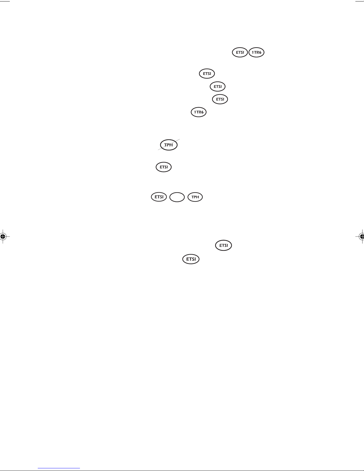
Setting up a User-Defined Bearer Service ...... 4-14
Entering Hexadecimal Numbers ..................................... 4-15
Setting the Bearer Capability
Setting the Low Layer Capability
Setting the High Layer Capability
Setting the Bearer Service
................................. 4-16
........................... 4-16
.......................... 4-17
..................................... 4-17
Channel Setup ................................................................ 4-18
Supplementary Service Selection................................... 4-20
Call Forwarding ................................................... 4-20
Call Deflection .................................................................. 4-29
Keypad Facility
Malicious Call Identification (MCID) ................................ 4-36
Making a Three Party Call ............................................... 4-37
Setting up CCBS
....................................................... 4-30
VN
(Completion of Calls to Busy Subscribers) ................. 4-40
Making a Call with CCBS Enabled ................................. 4-41
CCBS Error Messages .................................................... 4-44
CCBS Options Not Supported by AuroraPlus. ............... 4-44
Suspending and Resuming a Call
User-to-User Signalling
Setting up User-to-user Signalling .................................. 4-46
Sending an INVOKE Request .......................................... 4-50
Choosing how AuroraPlus Responds to
UUS INVOKE Requests................................................ 4-52
......................................... 4-46
........................ 4-44
Test Functions............................................................ 5-1
Autotest ............................................................................ 5-1
Setting up the Autotest ....................................................... 5-1
Running the Autotest ......................................................... 5-2
Checking the Line Configuration ...................................... 5-3
Automatically configuring the line under test ................... 5-4
Service Check: Determining Available Services................ 5-4
Performing a Local Service Check .................................... 5-5
Performing a Remote Service Check ................................ 5-6
Understanding Service Check Results ............................. 5-6
The X.25 Test .................................................................... 5-7
Testing Fixed Links ........................................................... 5-8
Performing a BER Test ..................................................... 5-8
Issue 5 - 04/01 vii
Page 12
Trend AuroraPlus User Guide
Downloading BERT Results to a PC ................................. 5-9
Starting a BER test ........................................................... 5-10
Understanding the BER Test Results .............................. 5-13
Displaying Test Results ................................................... 5-15
Displaying Tracer Output ................................................. 5-16
Downloading Tracer Results to a PC .............................. 5-17
Clearing Tracer from Memory .......................................... 5-18
Saving Results ................................................................ 5-19
Saving a Set of Results .................................................... 5-19
Displaying Results You Have Saved ............................... 5-20
Sending Results to a PC ................................................ 5-20
Entering the Customer and Operator Names ................. 5-20
Sending the Report .......................................................... 5-21
Self Test Functions ......................................................... 5-22
Performing a Self Test Function ...................................... 5-23
Upgrading AuroraPlus Software ..................................... 5-26
Performing a Status Check ............................................. 5-29
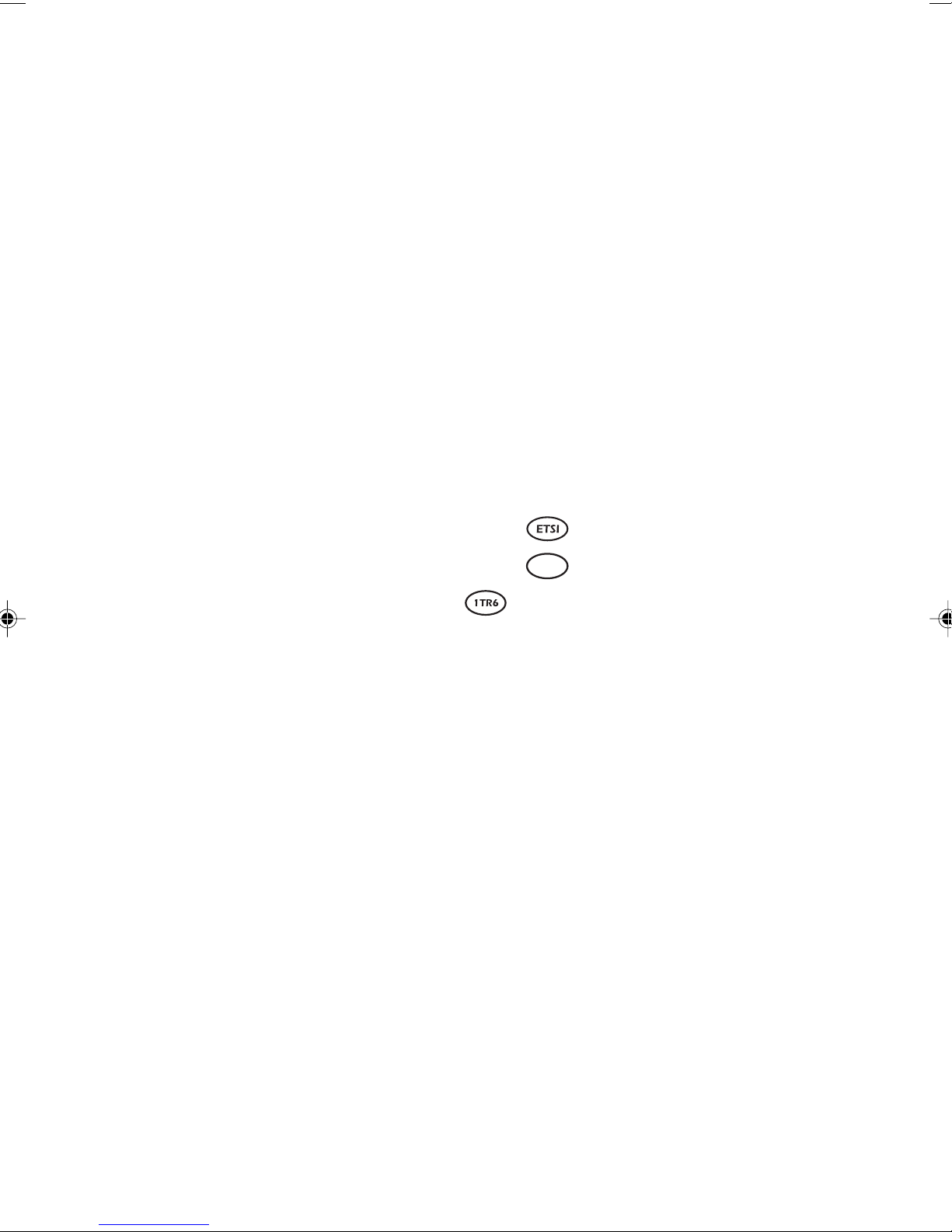
Checking Call Forwarding Status .......................... 5-29
Checking Call Forwarding Status
Checking Active Facilities ...................................... 5-31
VN
.......................... 5-31
Displaying Far End Block Errors/Near End Block Errors
(FEBE/NEBE) .............................................................. 5-33
Checking AuroraPlus's Status and the Line Voltage ....... 5-34
X.25 Calls ................................................................... 6-1
What is D-channel X.25 ? ................................................. 6-1
Setting up an X.25 call ..................................................... 6-1
Connecting a X.25 Call .................................................... 6-8
Receiving X.25 Calls ........................................................ 6-12
Spectrum B Stimulus and Functional (Optional) . 7-1
Introduction ...................................................................... 7-1
SPIDS (Service Profile Identifier) ...................................... 7-1
Spectrum B Functional .................................................... 7-1
Bearer and teleservices .................................................... 7-1
Supplementary Services ................................................... 7-2
Spectrum B Stimulus and Functional ............................... 7-2
Main Menu ......................................................................... 7-2
Changing the SPID (Service Profile Identifier) ................. 7-3
Spectrum Stimulus Call Setup .......................................... 7-5
Performing a BER test ....................................................... 7-6
Viewing messages sent by the network ............................ 7-7
viii 429850
Page 13

Contents
Testing on Analogue Lines with
AuroraPlus (Optional) ............................................... 8-1
Preparing AuroraPlus for Analogue Lines ......................... 8-1
Analogue Setup................................................................ 8-2
Setting the Dial Mode ........................................................ 8-2
Storing Speed Dial Numbers ............................................ 8-2
Setting Language & Loudspeaker Options ....................... 8-3
Answering Incoming Calls ................................................ 8-3
Making Outgoing Calls .................................................... 8-4
Overlap Dialling ................................................................. 8-4
En Bloc Dialling .................................................................. 8-5
Speed Dialling ................................................................... 8-6
While a call is connected ................................................. 8-6
Switching between Pulse and DTMF dialling ................... 8-7
Putting a call on hold ......................................................... 8-8
Displaying the Meter Pulse Count .................................... 8-9
The 40kHz Generation Test ............................................. 8-10
Technical Data ..........................................................A1-1
Glossary and Acronyms .......................................... A2-1
Menutrees ............................................................... A3-1
Call Clearing Cause Codes .....................................A4-1
Index
Issue 5 - 04/01 ix
Page 14

Trend AuroraPlus User Guide
x 429850
Page 15

Introducing AuroraPlus
Welcome !
Introducing AuroraPlus
This chapter introduces you to the documentation provided
AuroraPlus and the conventions used throughout it. It
with
also outlines the main features of
introduction to ISDN.
Welcome to the Trend AuroraPlus User Guide. This guide
contains information on using your
safety information, technical details and an introduction to
ISDN. If you are a new user you may find it helpful to spend
time familiarising yourself with this guide so that you know
where to find information when you need it. The structure
of the guide is as follows :
AuroraPlus and provides an
AuroraPlus together with
1
Chapter 1 (this chapter) introduces you to
ISDN.
Chapter 2 describes the controls, switches, connectors and
power supply. Also discussed is how to display, select from
and navigate through the menu structure.
Chapter 3 tells you how to set up
for testing.
Chapter 4 describes how to accept and make voice and data
calls.
Chapter 5 describes how to perform various test functions
with your
Check.
Chapter 6 describes how to use
generic packet mode.
AuroraPlus - for example a BER Test or a Service
AuroraPlus
AuroraPlus to test in X.25
AuroraPlus and to
in preparation
Issue 5 - 04/01 1-1
Page 16

Trend AuroraPlus User Guide
Chapter 7 describes how to use AuroraPlus to test on a
network using Spectrum B Functional or Spectrum B
Stimulus.
Chapter 8 describes how to use
lines.
Appendix 1 lists technical information relevant to your
AuroraPlus.
Appendix 2 provides a glossary of terms and abbreviations
used throughout this Guide.
Appendix 3 contains menutree diagrams to help you navigate
through the menu structure.
Appendix 4 explains the Cause Code and clearing location
information provided by
Conventions in the Guide
The conventions used throughout this Guide are explained
below:
AuroraPlus to test on analogue
AuroraPlus.
Protocol Symbols
Differences between the public protocols supported by
AuroraPlus (ETSI, 1TR6, TPH and VN) are indicated
throughout this guide using symbols. For example, text that
applies to VN only is indicated using:
VN
Text that does not apply to VN is indicated by a line through
the symbol :
VN
Unlabelled text applies to all protocols.
1-2 429850
Page 17
Introducing AuroraPlus
Special Typefaces
To help you distinguish them, menu options are shown in a
different typeface - for example ‘choose SETUP’.
The names of keys are displayed in bold, italic typeface - for
example ‘press ENTER’.
Other Symbols
Tip Indicates a useful tip.
Note This symbol is used to draw your
attention to important notes.
Hot Keys Indicates the Hot Key combination
to access the function quickly.
Notes
• ETSI is used to denote the Euro ISDN protocol
• The text and illustrations in this User Guide describe a
• The text and illustrations in this User Guide describe all
• The term reference point and interface (R, S, T, S/T or
• The term ‘S bus’ refers to an ‘S’ Point-to-Multipoint
Warning This symbol highlights warnings or
cautionary notes.
throughout this manual.
typical
configuration and may include features that you did
not purchase.
the features available on
able to select certain menu items if your organisation
did not purchase these options.
U) are used interchangeably.
connection, while S usually refers to a Point-to-Point
connection known as the ‘T’ reference point.
AuroraPlus. They may not match your specific
AuroraPlus. You may not be
Issue 5 - 04/01 1-3
• The term ‘POTS’ (Plain Old Telephone System) is used
to refer to the service that is also known as PSTN or
analogue telephony.
Page 18

Trend AuroraPlus User Guide
Your AuroraPlus
AuroraPlus is an easy-to-use, hand-held Basic Rate ISDN
tester. It enables various types of ISDN calls and connections
to be tested and its menu-driven display allows easy
operation and programming.
features associated with a modern ISDN telephone and
optionally a standard analogue telephone. AuroraPlus can also
perform audio monitoring on an analogue telephone line.
Types of AuroraPlus
Various types of AuroraPlus unit are available. There are three
basic types, classed according to region of operation and the
type of line coding in use on the ISDN ‘U’ interface:
• non-US 2B1Q unit
• US 2B1Q unit
• 4B3T unit
Within these basic types there are other options related to
the power source for the unit:
AuroraPlus contains many of the
• Line powered unit - power is taken from the line.
• Battery powered unit - you can power the unit from a
battery, the optional charger or the ISDN line.
Available with all basic unit types.
•‘Combi’ unit - a battery powered unit which can also
be used to test analogue telephony. Available with all
basic unit types.
Features
• 4 x 12 line character, backlit display providing an easyto-navigate, intuitive menu structure.
• Easy-to-use keypad providing:
- ‘Hot Keys’ for direct access to functions
- Direct DTMF support with * and #
1-4 429850
Page 19

Introducing AuroraPlus
• Operation on U (2B1Q or 4B3T) and S/T interfaces.
• Protocols: ETSI (Euro ISDN) 1TR6 and VN.
• Support for both Point-to-Point operation (‘T’
reference point) and Point-to-Multipoint (S-bus)
operation.
• Call state and layer state information.
• Supplementary Service Support including:
- Call Hold and Retrieve
- Call Forwarding
- Call Waiting
- 3 Party Conference Call Facility
- CCBS
- Call Deflection
- Terminal portability
- User to User Signalling
• Support for bearer and teleservices:
TPH ETSI & 1TR6 VN
Tele-ISDN Tele-ISDN Tele-ISDN
3.1k Audio 3.1k Audio 3.1 Audio
Telefax Group 3 Data 64 kbit/s Telefax Group 3
Telefax Group 4 Telefax Group 3 Telefax Group 4
Data 64 kbit/s Telefax Group 4 Data 64 kbit/s
Teletex 64 Speech Teletex 64
Telex Data 56 kbits/s Telex
Mixed Mode Teletext 64 Speech
SVideo X21UC4 7k Audio
PVideo X25UC8 7k Telephony
Videotext BTX Data 56 kbit/s
OSI BTX New Mixed Mode
Timelink Audiovisual Video
tele-check Mixed Mode Videotex Syntax
Audiovisual Remote Control Videotex Int'l
tele-check GRPTEL OSI
User defined X.25 D channel tele-check
Speech tele-check Video phone
X.25 D channel User-defined MSGPRO
X.25 D channel
User-defined
Issue 5 - 04/01 1-5
Page 20

Trend AuroraPlus User Guide
• Storage of up to 99 lines of D channel protocol
data which can be reviewed on-screen or
downloaded.
• Serial Port
• BER Testing with a range of duration times
• X.25 Testing
• Facility for checking services available from the
exchange and the acceptance of calls at ‘R’, ‘S’, ‘T’ and
‘U’ reference points over the Basic Rate ISDN
• Audio monitoring function on a two-wire interface
• Self Testing
- to flash EPROMs for software upgrade
- to output stored data
• Call Redial
• 5 ‘Speed Dial’ number entries
• Setting of Multi-Subscriber Number (MSN) in the ETSI
protocol
• Testing of voiceband and data calls
• Displays A-subscriber numbers (Calling Line Identity)
during calls
• Display of line voltage on analogue (POTS), U and S
connections
• Display of number while dialling
• Power feed from U or S/PS1 normal or restricted mode
• Unit protection via a short-circuit of direct supply
voltage
• Voltage resistant up to 240V DC on the U Interface
• Ringer. An incoming call is signalled via the built-in
ringer.
• Retention of all programmed data in nonvolatile
1-6 429850
memory after the tester is disconnected from the
network or switched off.
Page 21

Use
Introducing AuroraPlus
• Loudspeaker monitor
• 40 kHz generator at -12dBm for a two-wire interface
with a TIMS test set
• Loop formation on analogue lines (POTS)
• Analogue standard telephone (optional)
• Battery operation (optional)
You can use your AuroraPlus held in the hand, like a telephone
handset, or laid on its back. There is also a hook (two on the
'combi' model) on the back of
AuroraPlus
so that you can hang
it up.
Your AuroraPlus is designed to test the ISDN Basic Rate
Interface (BRI) at the ‘S’, ‘T’ and ‘U’ reference points, by
emulating a Terminal Equipment (TE).
Making and clearing a Basic Rate connection between the
terminal and the network uses a D channel communication
protocol.
AuroraPlus tests the correct operation of this
protocol and reports the success or failure of the call on its
Liquid Crystal Display (LCD). Please note that detailed
explanations of application protocols are not included in this
guide.
When you have made or answered an ISDN call, (either voice
or data)
AuroraPlus
lets you test the integrity of the
connection. For voice calls, this may be a speech test or Bit
Error Rate (BER) Test and, for data calls, a BER Test.
Issue 5 - 04/01 1-7
Page 22
Trend AuroraPlus User Guide
Supplied with AuroraPlus
AuroraPlus is supplied with the following items:
• a 6-pole RJ45 to RJ45 cable for S interface testing
• for French units, a cable with 4m 'banana' plugs and
crocodile clips for U interface testing
• a serial port connector cable for direct communication
with a PC serial port
• installation software, where required
• for battery and analogue units, a power charger
(European, US or UK)
• this User Guide
• a carrying case (optional accessory)
Looking after AuroraPlus
AuroraPlus has been designed and constructed to withstand the
rigours of a typical telecommunications working environment.
It can be used in wet conditions but is not waterproof and
will not withstand excessive ingress of water.
Caution
Do not use solvents, strong detergents, or abrasive materials to
clean your
use on plastics.
AuroraPlus. Use only cleaning agents approved for
Safety Advice
When using AuroraPlus, basic safety precautions should always
be followed to reduce the risk of fire, electric shock or injury,
including the following:
• The serial port, the DC Power Input Connector and the
Interface Connector must not be connected to mains
power outlets. The Interface Connector should only be
connected to authorised ISDN or analogue lines.
1-8 429850
Page 23

• When supplied with a power adaptor/charger, AuroraPlus
must only be used with that adaptor/charger. The use
of any other adaptor/charger may invalidate approvals
relating to safety or electromagnetic compatibility.
• Do not open the back of the unit when it is switched
on or connected to the network.
• Avoid using the product during an electrical storm.
There may be a remote risk of electrical shock from
lightning.
Where to get more information
If you would like more information about AuroraPlus or other
Trend products, contact your sales representative or the
Trend Communications Ltd. Help Desk:
Introducing AuroraPlus
Within the UK: 08457 660 854 (local rate)
Within France: 01 69 35 54 75
Within Germany: (0) 89-32 30 09-43
Other countries: + 44 1628 851085
Issue 5 - 04/01 1-9
Page 24
Trend AuroraPlus User Guide
ISDN Explained
What is the ISDN?
The ISDN is an evolutionary circuit switched network based
on digital telephony. It uses a common set of interface
standards and allows users to send and receive information
over the network.
ISDN offers end-to-end (caller to receiver) digital
connectivity between Terminal Equipment (TEs), via
Network Terminators (NTs) and digital exchanges, both
private and public.
ISDN Services
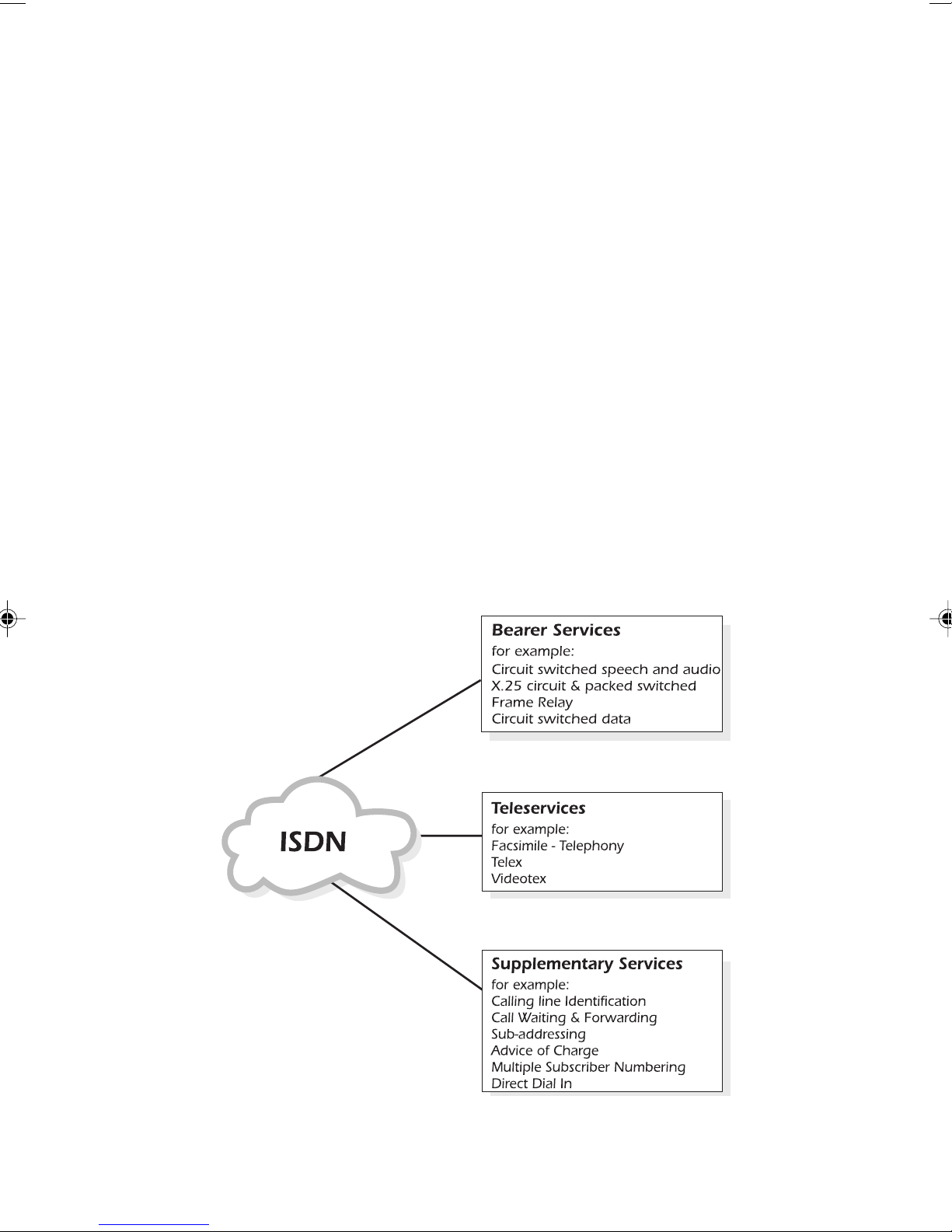
ISDN services are the telecommunication services to which
the user has access either at an ISDN interface or a terminal
connected to the ISDN. The diagram below summarises the
services offered:
1-10 429850
Page 25
Equipment on the ISDN
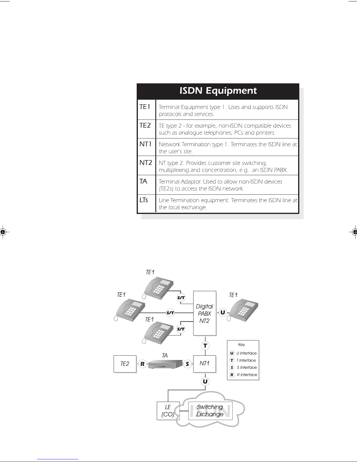
Each piece of equipment (‘functional group’) on the ISDN
has a label related to the function it performs. The labels are:
Introducing AuroraPlus
ISDN Interfaces
An interface (‘reference point’) is said to exist between each
piece of equipment on the ISDN.
Issue 5 - 04/01 1-11
Page 26

Trend AuroraPlus User Guide
Notes
In a typical BRI installation NT1 and NT2 functions are
combined in single NTE (Network Termination Equipment).
ISDN Standards
ISDN is subject to standardisation by the ITU-T and ETSI,
which issue recommendations and specifications covering
ISDN equipment and interfaces. Standards also exist for
types of service, protocols and ISDN numbering.
Pulse Code Modulation
Pulse Code Modulation (PCM) is a method of converting
analogue signals into digital code. An analogue waveform is
sampled at regular intervals and a measurement is taken of
the sample point at various levels. The number obtained is
digital. The receiver recovers the original analogue signal by
reversing the conversion.
The sampling rate is 8kHz, and the sample value is translated
into an 8 bit code, to conform with ITU-T G.711. Therefore
each speech signal results in a continuous bit stream at a rate
of 64 kbps.
The process of converting between analogue and digital is
known as encoding. An encoding device when combined
with a decoder is called a Codec.
Methods of Voice Encoding
The number of levels used in the sampling, and the way they
are spread, affect the amount of signal noise and distortion.
There are two methods of encoding within the ITU-T G.711
recommendation: A-Law and µ-Law.
A-Law encoding
This is the type of voice encoding used in Europe. Sampling
consists of 4096 levels, divided into 7 segments.
1-12 429850
Page 27

µ-Law encoding
This is the type of encoding used in the United States, Japan
and some other regions of Asia. Sampling consists of 8159
levels, divided into 8 segments.
Line Coding Techniques
To overcome the technical difficulties raised by sending
digitised information down a telephone cable originally
designed for 50V pulse dialling and 4kHz speech, line coding
is used. There are a number of different techniques: each one
involves coding digitised speech into different voltages which
can then be transmitted down the telephone lines.
2B1Q line coding
Introducing AuroraPlus
The name 2B1Q comes from the method of coding 2 binary
digits (2B) as one of 4 voltage levels (1Q, where Q stands for
‘quaternary’).
4B3T line coding
The name 4B3T comes from the method of coding 4 binary
digits (4B) as a group of 3 voltage levels (3T, where T stands
for ‘ternary’).
Basic Rate & Primary Rate ISDN
Equipment on an ISDN network may be connected either
through a Basic Rate interface or a Primary Rate interface.
• Basic Rate (BRI) consists of two B channels and one D
channel, known collectively as 2B+D.
• Primary Rate (PRI) consists of 30 B channels and one
D channel (‘30B+D’) in Europe, and 23 B channels and
one D channel (‘23B+D’) in the US.
Issue 5 - 04/01 1-13
The B channels contain user data at rates of up to 64Kbps.
The data is switched by the network in order to provide an
end-to-end transmission service.
Page 28
Trend AuroraPlus User Guide
In Basic Rate the D channel carries control and signalling
data at 16kbps. It may also be used for X.25, the Packet
mode service.
Basic Rate access to the ISDN
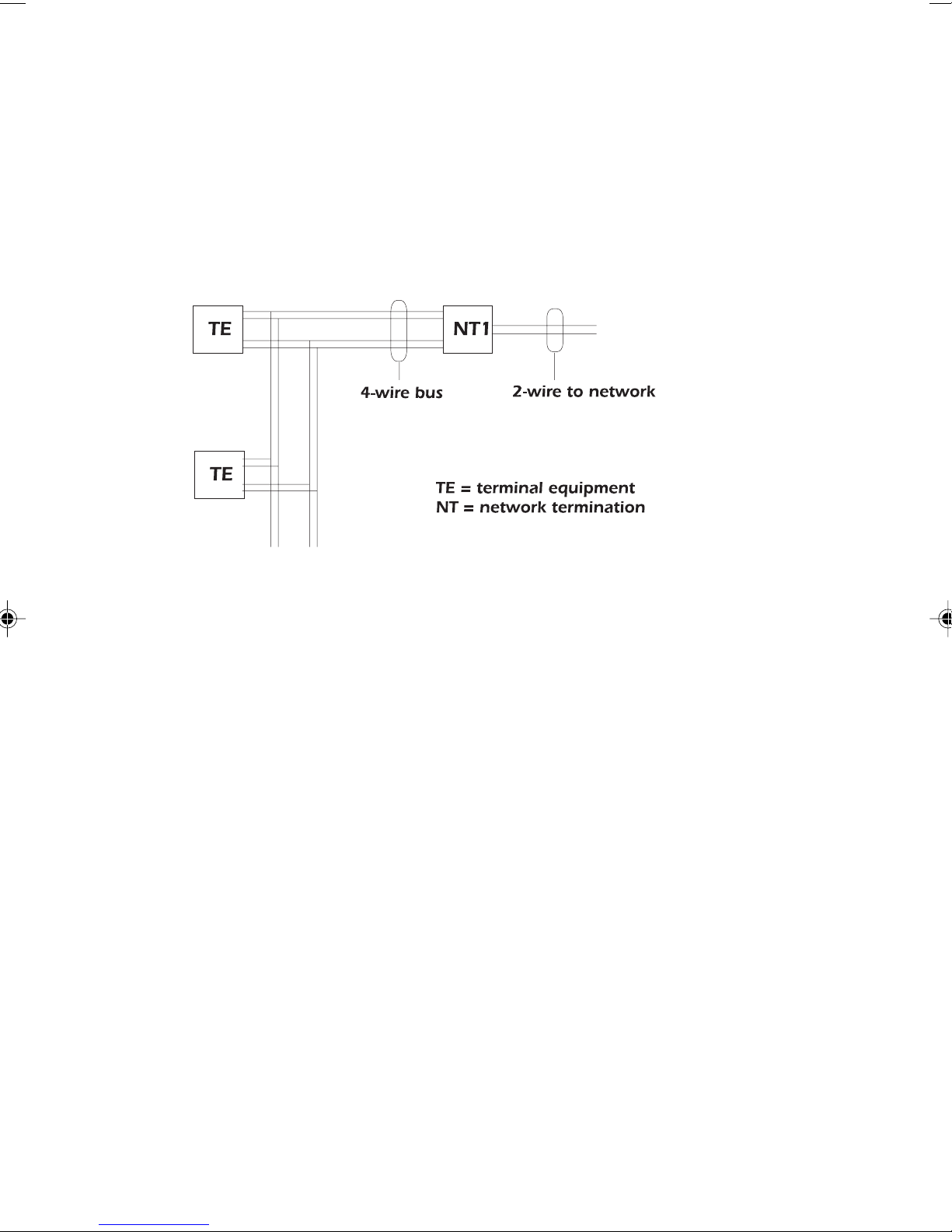
The diagram below illustrates Basic Rate ISDN operation.
In this illustration, a 4 wire interface consisting of a transmit
and receive pair (known as the ‘S/T interface’), is connected
to the NT1. The S/T interface is terminated at the NT1 and
the distant end, on both the transmit and receive pairs.
Connection to the interface is usually made via 8-pin plugs
which conform to ISO Specification 8877. Over this
interface pass the 2B+D channels.
Point-to-Point and Point-to-Multipoint links
The layer 2 of a S/T interface can operate in either
Point-to-Point (PP) or Point-to-Multipoint (PMP) mode.
• On a PP link, only one TE may be connected at the end of up
to 1km of cable.
• On a PMP link, up to 8 terminals can be connected in
parallel along the bus. The length of the bus is limited to
about 200m, depending on the cable.
1-14 429850
Page 29

Basic Rate power
Power is provided across the network so that, in the event of
a local mains power failure, a basic telephone service is still
provided.
The OSI 7-Layer Model
The Open Systems Interconnection (OSI) is an agreed,
international standard governing the way systems
communicate. The standard model has seven layers, as
follows:
Layer 1 The physical layer. Transmits bits between the
terminal and the network. It defines
connectors, line coding, transmission rates and
Introducing AuroraPlus
anything else concerning the transfer of bits.
Layer 2 The data link layer. Provides link level control.
Error detection and correction are handled by
assembling the bits into frames. All Layer 2
formats derive from a standard known as High
Level Data Link Control (HDLC).
Layer 3 The network layer. Routes messages to their
destination.
Layer 4 The transport layer. The end-to-end layer
which sets up and maintains connections.
Layer 5 The session layer. Handles the co-ordination
between processes.
Layer 6 The presentation layer provides data
Issue 5 - 04/01 1-15
formatting and code conversion.
Layer 7 The application layer. This is the task to be
performed, e.g. remote login and file transfer.
Page 30

Trend AuroraPlus User Guide
Layer 1 (BRI)
Layer 1, at the S/T reference point, transfers information bits
in frames between the terminals and the NT1.
Each layer 1 frame is 48 bits long and lasts for 250
microseconds—its structure depends on the direction of
transmission. It contains two 8 bit groups of channel B1,
two 8 bit groups of channel B2, 4 bits of channel D and 12
bits used for other functions.
D Channel Contention
If two TEs attempt to make a call simultaneously, a
procedure known as D Channel Contention Resolution
prevents a collision.
Activation and deactivation
TEs and NTs can be deactivated in order to reduce power
consumption, then reactivated to normal power. Both the TE
and NT can receive activation messages, but only an NT can
instruct a TE to deactivate.
‘Info’ signals
Activation and Deactivation messages are transmitted using
‘Info’ signals.
Info 0 idle state—neither the TEs or the NT are operating.
Info 1 TE to NT—requests activation.
Info 2 NT to TE—requests activation/responds to
Info 1.
Info 3 TE to NT—contains operational data.
Info 4 NT to TE—contains operational data.
1-16 429850
Page 31
Layer 2
Introducing AuroraPlus
Layer 2 provides a secure, error-free connection for Layer 3
call control information, by organising the Layer 3 octets
into error checked frames. Layer 2 procedures, based on
HDLC, are known as Link Access Procedure for a D
Channel (LAPD).
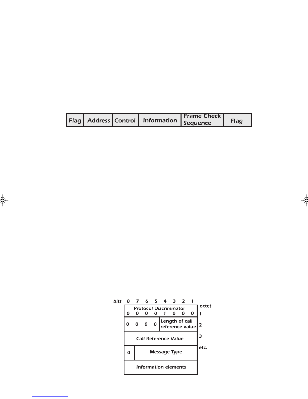
A Layer 2 frame is structured as follows:
Flags Indicate the start and end of the frame.
Address A unique value identifying the message type
and the channel to which it refers. Contains
a SAPI (Service Access Point Indentifier) to
identify the service that the frame is
intended for, a TEI (Terminal Endpoint
Indentifier) to identify the terminal, and a
Command/Response bit.
Layer 3
Control Carries information that identifies the
frame.
Information Carries the TEI management protocol or
layer 3 message.
FC Sequence Used for error detection.
Layer 3 routes messages to their destination. The diagram
below shows the structure of the Layer 3 signalling messages.
Issue 5 - 04/01 1-17
Page 32

Trend AuroraPlus User Guide
Protocol Discriminator Identifies the protocol.
Call Reference Value Identifies the call with which a
Message Type Describes the intention of the
Information Elements A number of these may be
Protocols
A protocol is an agreed set of rules for carrying out a
message is to be associated.
message: CONNECT, SETUP,
etc.
included. The number and
content depend on the message
type.
particular function such as the exchange of information.
ETSI
The ITU Q921 and Q931 recommendations are the basis of
what is commonly known as the ETSI protocol. Q931
defines the call control messages and Q921 defines the
frames that carry the messages. ETSI is the standard ISDN
protocol used within Europe.
VN
VN is the national ISDN protocol for France and it is also
used in private networks utilising equipment of French
origin. VN is similar in many respects to the ETSI protocol,
the main differences being the construction of layer 3
messages and information elements, new message types and
different teleservices.
1-18 429850
Page 33

Introducing AuroraPlus
1TR6
The national protocol for the ISDN environment in
Germany. Also often used in private networks utilising
equipment of German origin.
TPH
The national protocol for the ISDN environment in
Australia. Also often used in private networks utilising
equipment of Australian origin.
Issue 5 - 04/01 1-19
Page 34

Trend AuroraPlus User Guide
1-20 429850
Page 35

Getting Started
This chapter describes the controls, switches, connectors and
power supply. Also discussed is how to display menus, scroll
through them and select options.
Note
If your AuroraPlus is fitted with batteries (battery and combi
units) it was supplied with the batteries uncharged. We
recommend that you fully charge the batteries before starting
to use
NiMH cells exhibit a 'memory', which means that if you
repeatedly recharge a battery which is only partially
discharged, a small amount of its capacity is lost. This should
not normally be a problem, but approximately once a month
you may wish to discharge the battery completely before
AuroraPlus.
Getting Started
2
recharging it.
Issue 5 - 04/01 2-1
Page 36
Trend AuroraPlus User Guide
A Look at AuroraPlus
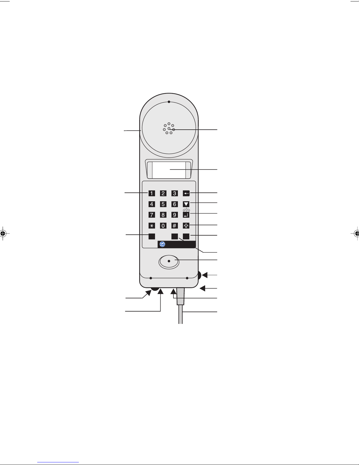
Controls, switches and connections are shown in the
following illustration.
Loudspeaker Monitor
POTS Check switch
ISDN/POTS switch (optional)
(optional)
Keypad buttons
0...9, & #
*
AuroraPlus
Earpiece
LCD Display
Clear button
Scroll button
Enter button
Shift button (Yellow arrow)
Change-over
switchU-S
Termination switch
Mouthpiece
Battery/Charging Switch (optional)
Charging socket (optional)
Charging LED (optional)
Serial Port
2-2 429850
S&UorAnalogue
Connection cable
(interchangeable)
Page 37
The Keypad
8
21 3
54 6
7
0
9
▲
#
CONFIGX.25 SERVICE
STATUSINFO
TERMPOTS CHK
OFF
ON
OFF S
ON U
S/U
HOMEABC
DEF
GHI
PQRS TUV
WXYZ
JKL MNO
B SEL
BERT
LOOP
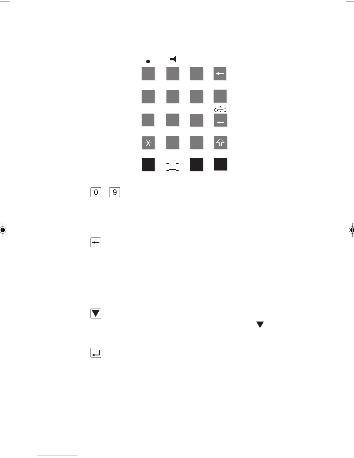
... These are numeric keys for dialling digits and entering
Getting Started
numbers. Keys 0 to 9 can be used for dialling numbers,
entering codes and selecting functions. They form the keypad
of the
AuroraPlus.
Clear Key
In screens that allow you to enter a number (for example,
the Dial screen) this key deletes the most recently entered
digits that appear on the display. In all other screens, press
this key once to move up a level in the menu structure. Also,
use with the SHIFT key to return 'home' to the Main Menu.
Scroll Key
This is used to display more information when appears on
the screen.
Enter Key
This key is used to initiate or terminate a call. The ENTER
key can also be used for making selections.
Issue 5 - 04/01 2-3
Page 38
Trend AuroraPlus User Guide
Shift Key
The SHIFT key is used in combination with other keys to
access additional functions - these are known as Hot Key
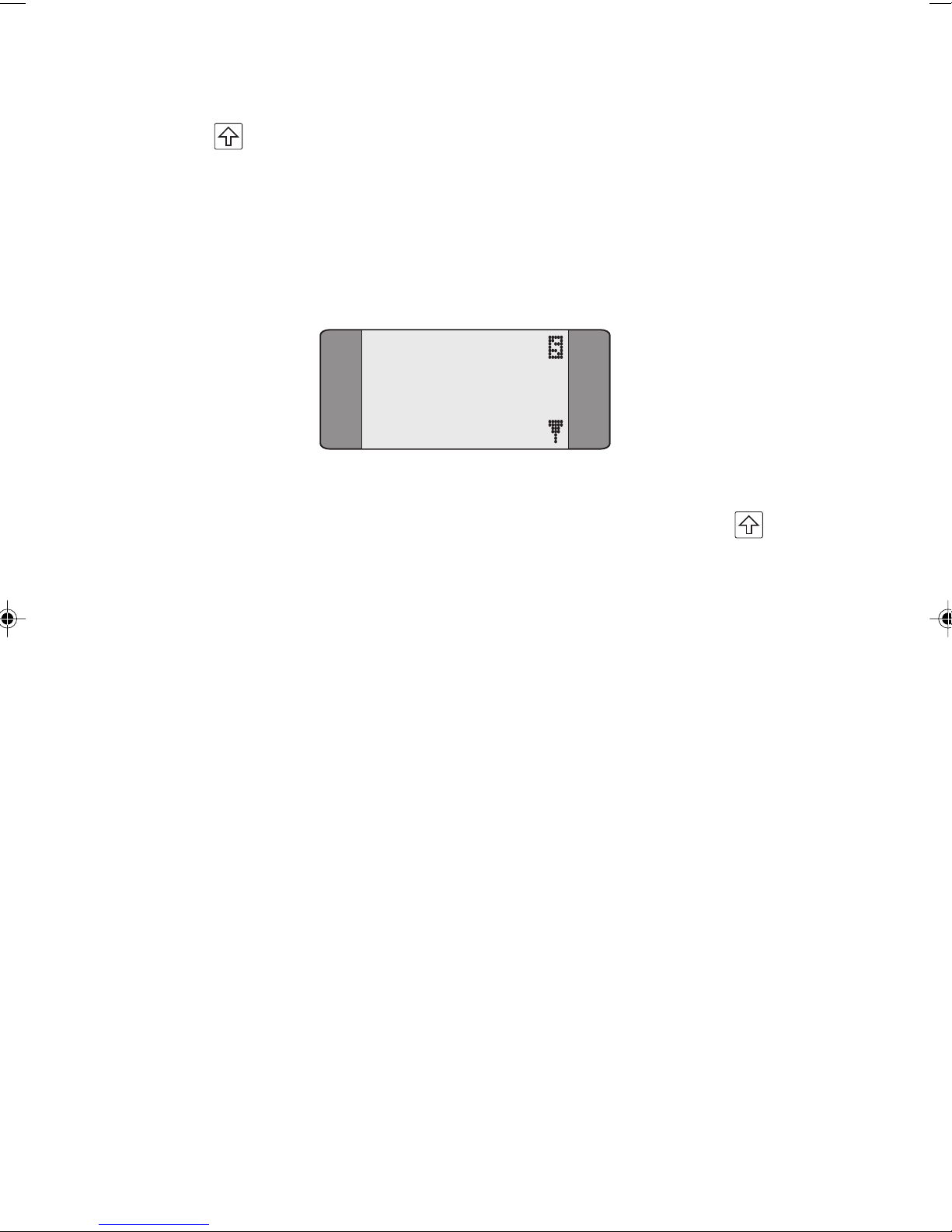
functions. When you toggle the SHIFT key an 'S' appears in
the top, right of the screen to indicate you are about to
trigger a shift function:
1 CALLS
2 TESTS
3 AUTOTEST
4 RESULTS
Functions displayed in yellow on the keypad are accessed by
combining that particular key with SHIFT - for example
+ 5 for a BER Test. Please refer to Using Hot Keys in this
chapter for further details.
Switches
S/U Change-Over Switch
The S/U Change-Over Switch is used for switching between S
or U Interface lines. The supplied S and U access cables are
used for connection to the Basic Rate line. The switch has
two positions:
UP S Interface
DOWN U Interface
Changing between S-Bus and U-Interface operation
With AuroraPlus switched on, unplug the connection to
AuroraPlus.
Press the S/U button.
AuroraPlus reboots and the new interface is now active.
2-4 429850
Page 39

Getting Started
Connect the new connection to the RJ45 connector located
at the base of
AuroraPlus.
The Network Terminator (NT) must be disconnected before
connecting
Equipment (TE) must be disconnected before
AuroraPlus to a U Interface line. The Terminal
AuroraPlus is
connected to an S Interface Point-to-Point connection.
After connection onto either the S or U Interface, the display
indicates Idle. When you try to make a call the unit initialises
the connected interface. On the S Interface this is almost
instantaneous and is not visible. On the U Interface this can
take a minute or so. During this time INIT U is displayed.
When the interface is initialised, the call progresses to the
next stage of the call establishment procedure.
POTS Check Switch (Only via U Access Cable)
The POTS Check function is activated by the POTS Check
Switch, marked 'POTS CHK'. The high impedance circuitry
means that the handset can be used to listen to analogue
signals on the line. The switch has two positions:
UP POTS Check is off
DOWN POTS Check is on
When the TERM switch is in the DOWN position, if the
line is idle, when you press the TERM Switch the unit draws
analogue dial-tone.
Important Note
The POTS CHK switch must be in the UP position, before
connecting
introducing bit errors. Do not change the position of the
switch while the tester is connected to the line.
AuroraPlus to the U Interface line, to avoid
Issue 5 - 04/01 2-5
Page 40

Trend AuroraPlus User Guide
Battery Charging Switch (Optional)
AuroraPlus can be powered from an external charger or from
an internal rechargeable battery in both ISDN and Analogue
modes. The two switch positions are:
BAT Power is supplied from the internal
rechargeable battery, even when the charger is
connected.
CHARGE The internal battery is charged if the charger is
connected. If the charger is not connected,
setting the slide switch to the CHARGE
position acts as an off switch.
Charging is indicated by the red charging LED,
next to the charger connection socket. The
LED flashes when the charging process is
completed.
Battery Low Warning
When the remaining battery charge drops to 30 minutes, an
audible signal is sounded and a warning is displayed on the
screen. This screen is redisplayed every 30 seconds. If the
battery level drops still further, before it fails completely, the
unit switches itself off. It cannot be switched on again until
the external charger is connected.
Termination Resistor Switch (TERM)
Correct operation of the S-bus connection (Point-to-Point or
Point-to-Multipoint) can depend on the customer wiring
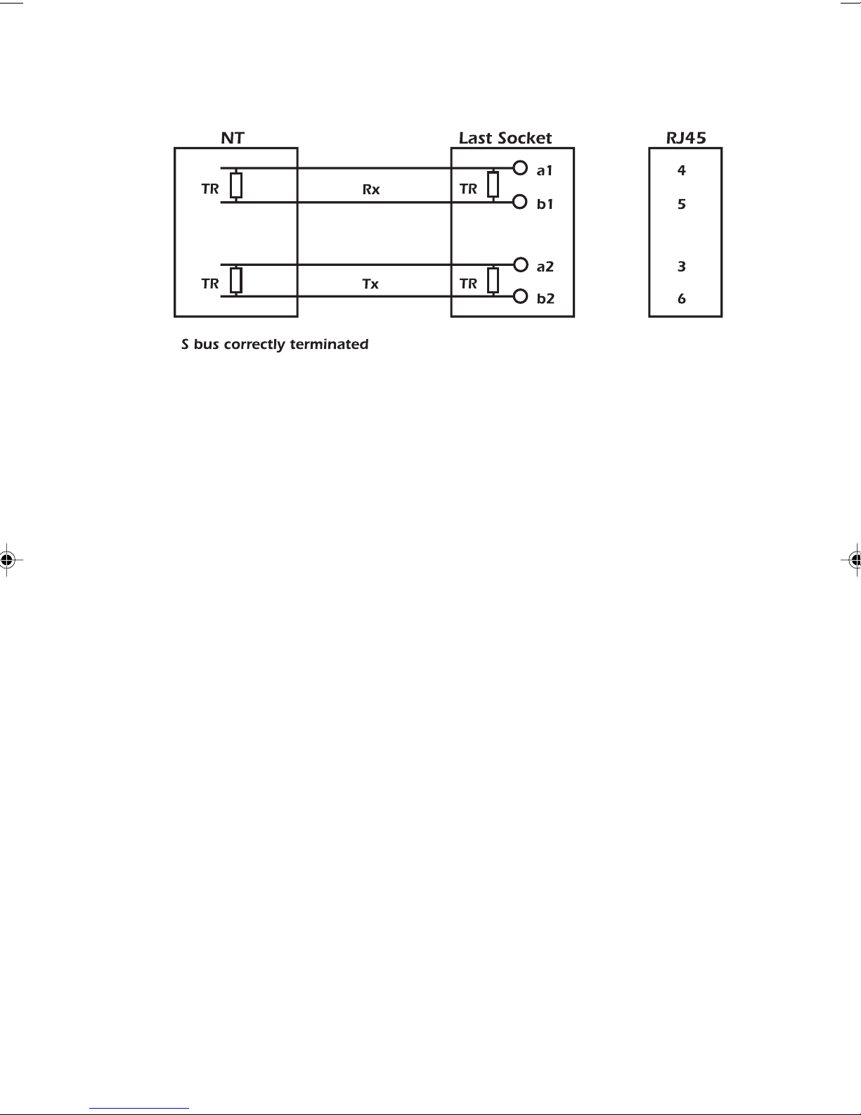
being correctly terminated. The wiring must be terminated
with 100 ohms at either end of the S-bus connection in both
directions, i.e. Transmit (Tx) and Receive (Rx).
2-6 429850
Page 41
Getting Started
If there are no resistors in the wiring the termination can be
achieved with
AuroraPlus. Set the Termination Resistor Switch
as follows.
DOWN Additional termination resistors are connected
on the line.
UP There is no termination by AuroraPlus.
If the TERM switch is depressed while in POTS Check mode
the unit draws analogue dial-tone.
For use of this function, refer to the section titled POTS
Check Switch earlier in this chapter.
Interface Switch (Optional)
The Interface Switch is used to select either the ISDN or
Analogue interface.
Issue 5 - 04/01 2-7
ISDN Selects ISDN mode.
AuroraPlus may be
connected to the S or U Interface.
ANALOG/ Selects Analogue mode. The two-wire cable
POTS may be connected to the telephone network.
Page 42
Trend AuroraPlus User Guide
Note
If you change the setting of the Interface Switch, you must
switch
AuroraPlus off and on again to apply this change.
Communication Ports & Connectors
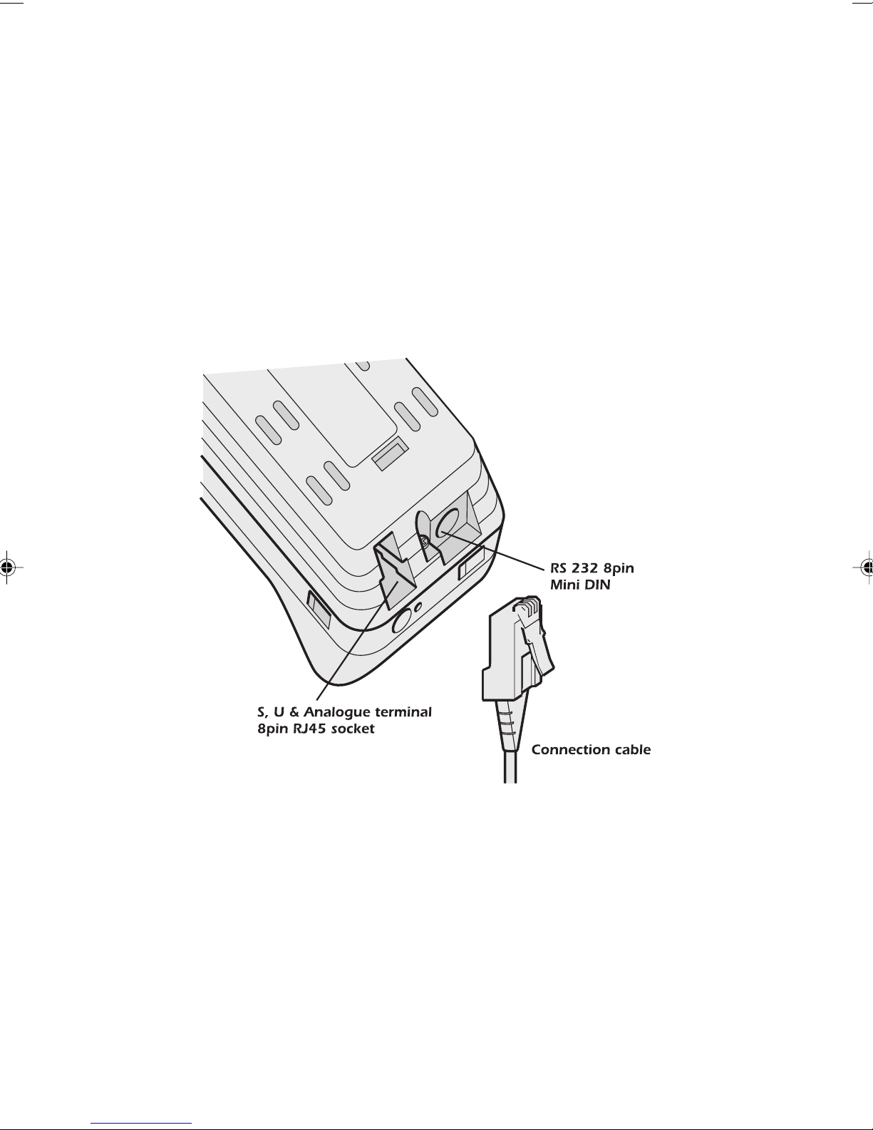
AuroraPlus's communications ports and connectors are located
on the bottom of the unit, as shown in the following
diagram:
2-8 429850
Page 43

Connecting AuroraPlus
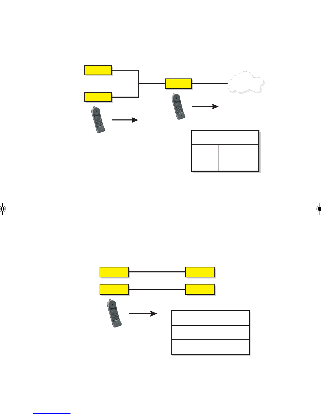
AuroraPlus can connect to the ISDN for Basic Rate testing on
the S or U interface, and can also be used for analogue
(POTS) testing.
Caution
When connecting to any interface, remember that high
voltages may be present on telecommunications lines.
Connections for testing
Plug the interface cable into the connector on AuroraPlus. The
cables are identified as follows:
• S interface: a black, 4-way cable with an RJ45 plug at
each end.
Getting Started
• U interface or analogue (POTS): a white, 2-way cable
with an RJ45 plug at one end.
Connect the other end of the cable to the equipment under
test.
• S interface: You can connect the cable either way
round. Plug one end into the unit and the other into
an S interface socket on the CPE side of the NT. This
can be a single connection or one connection on a 'bus'
of up to eight sockets.
• U interface: Connect the cable on the exchange or CO
side of the NT, with the NT disconnected.
• Analogue (POTS): connect to a 2-wire line from the
exchange of PBX extension.
Issue 5 - 04/01 2-9
Page 44
Trend AuroraPlus User Guide
POTS
POTS
PBX
PSTN
PBX Private Branch
Exchange
2 wire analogue
2 wire analogue
Key
PSTN Public Switched
Telephone Network
AuroraPlus
The following diagram shows the points on the ISDN where
you can connect and test using
TE
TE
AuroraPlus
Note
When connecting to the U interface, AuroraPlus may take a
few minutes to initialise before you can begin testing. During
AuroraPlus:
S
U
NT
AuroraPlus
ISDN
Key
TE Terminal
Equipment
NT Network
Termination
this process the screen displays a message telling you that the
U interface is initialising.
The following diagram shows how to connect
AuroraPlus for
analogue (POTS) testing:
2-10 429850
Page 45
Getting Started
Connecting to a PC
You would connect AuroraPlus to a PC to send test results or
protocol information to a PC file for analysis using Trend
AuroraExpert for Windows, or to download new software
using the TrendSend File Transfer Utility.
Using the serial cable, connect
serial port on the PC.
Switching Power On
If AuroraPlus is connected to a powered interface, it will
power up automatically.
If you are using an AuroraPlus with a built-in battery, slide the
CHARGE/BAT Switch, on the side of the unit, to the BAT
position to obtain power from the internal battery.
Alternatively, slide the switch to the CHARGE position and
connect to the external power supply to charge the battery.
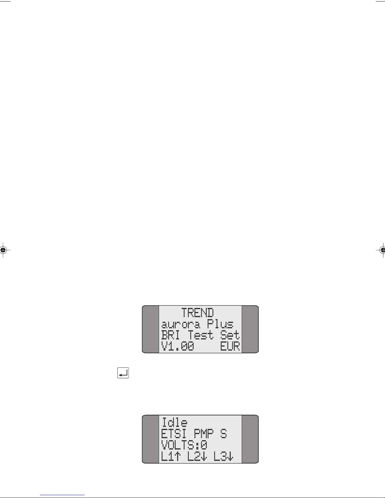
At power-on
opening screen. This tells you about the model, generation
and software version in use.
AuroraPlus performs a Self Test and displays an
AuroraPlus's serial port to the
Issue 5 - 04/01 2-11
Press ENTER to exit the Opening screen and display the Idle
screen (the Idle screen is automatically displayed after 5
seconds have elapsed).
Page 46
Trend AuroraPlus User Guide
This screen displays the current protocol, line type and
interface settings and any voltage detected on the line. The
bottom line indicates the layer status.
Tip
You can switch the backlight on the display on and off using:
+
Displaying the Main Menu
Press the ENTER key when the Idle screen is displayed. The
Main Menu is displayed:
1 CALLS
2 TESTS
3 AUTOTEST
4 RESULTS
Scrolling through Menu Pages
Menus which span over more than one page are indicated by
a down arrow symbol. For example, the Main Menu spans
over two pages:
1 CALLS
2 TESTS
3 AUTOTEST
4 RESULTS
2-12 429850
Page 47
To display the second page, press the SCROLL key:
5 SETUP
Press SCROLL again to toggle back to the first page.
Selecting Menu Options
Each menu option has a number associated with it. To
choose an option, use the keypad to input the number
associated with it. For example, to choose CALLS from the
Main Menu, press 1.
Getting Started
Note
If you are selecting a service type, a two digit number is
required, e.g. '01' to select TEL-ISDN (speech with telephony
HLC).
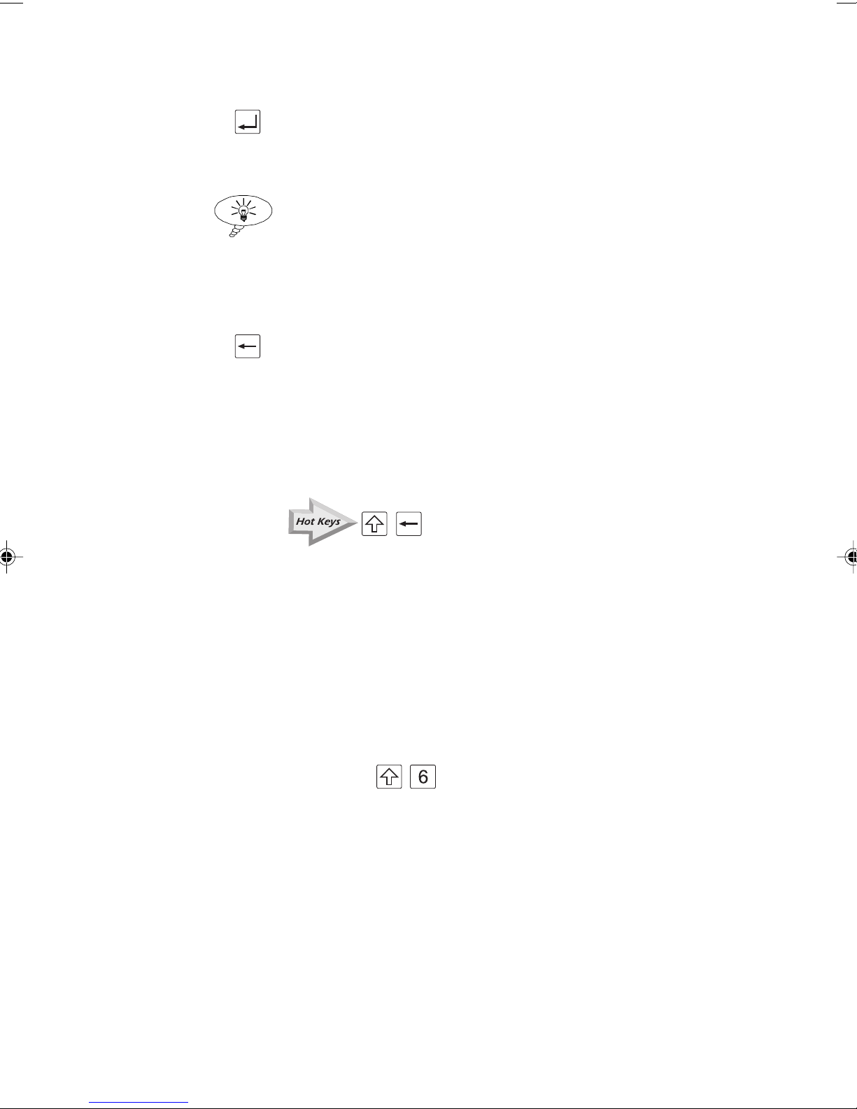
AuroraPlus uses an asterisk (*) symbol to identify current
settings. For example, in the following Line Type screen PMP
is selected.
1 CALLS
2 TESTS
3 AUTOTEST
4 RESULTS
Issue 5 - 04/01 2-13
Page 48
Trend AuroraPlus User Guide
Press ENTER to apply the current selection or input the
number of an alternative option and press ENTER to
confirm it.
Tip
Appendix 3 contains menutree diagrams to help you navigate
through the menu structure.
Exiting from a Menu
To exit from a screen press the CLEAR key. You return to
the previous screen.
Returning to the Main Menu
You can return 'home' to the Main Menu from any screen
using:
Using Hot Keys
Hot Keys let you access AuroraPlus's functions quickly,
without having to navigate through the menu structure.
To use a Hot Key, press the SHIFT key followed by the
number key associated with the function. When you press
SHIFT an 'S' appears on the screen to indicate you are about
to trigger a Hot Key. For example, to access the Loop
options press
+
+ .
2-14 429850
Page 49
Getting Started
The Hot Keys are as follows:
+ Displays information on the last or current call on the
selected B channel
+ Switches the backlight on and off
+ Switches the loudspeaker on or off
+ B Channel selection
+ Select BER test
+ Loop options
+ X.25 Test
+ Service Check
+ Line Configuration Check
+ AuroraPlus configuration and line voltage
+ Returns 'home' to the Main Menu
The Hot Keys are printed in yellow text on the keypad.
The Hot Key combinations are clearly marked throughout
this guide using a special symbol. For example:
+
Issue 5 - 04/01 2-15
Page 50

Trend AuroraPlus User Guide
2-16 429850
Page 51
Setting up your AuroraPlus
Setting Up your AuroraPlus
This chapter tells you how to set up AuroraPlus ready for
testing. The setup parameters you enter are stored in the
unit's EEPROM and are retained if the battery or external
power supply fails.
Displaying the Setup menus
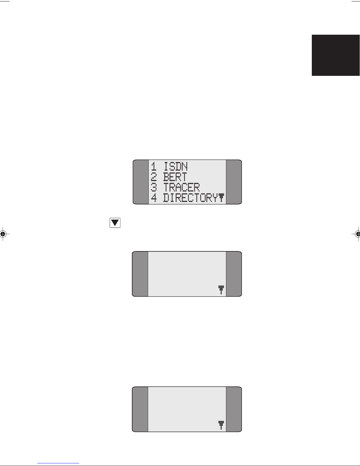
From the Main menu, choose SETUP:
Use the SCROLL key to display the second page of Setup
3
options.
5 GENERAL
6 TESTREPORT
7 AUTOTEST
Selecting Protocol & Line Type
This section describes how to select a different protocol or
line type.
Choose ISDN from the Setup menu to display the following
screen:
1 PROTOCOL
Issue 5 - 04/01 3-1
2 LINE TYPE
3 LOOP
4 CALL SCRN
Page 52
Trend AuroraPlus User Guide
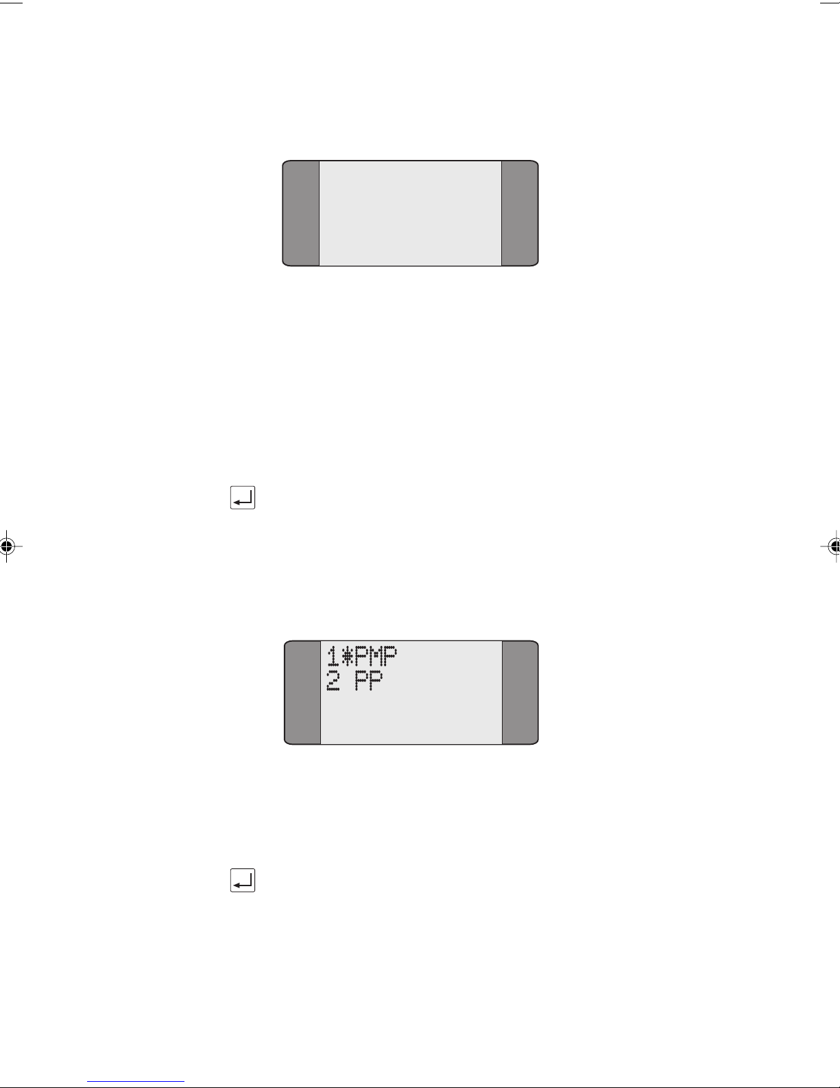
Choose the PROTOCOL option.
1*ETSI
2 1TR6
The list of protocols displayed may vary, depending on the
software loaded on your
Changing the Protocol
Choose the required protocol. An asterisk (*) symbol is
displayed against the current selection. The above example
shows the selection of the ETSI protocol.
Press the ENTER key to confirm your choice.
Changing the Line Type
Choose LINE TYPE from the ISDN SetUP menu to change the
connection type. The following screen is displayed:
AuroraPlus.
Choose the appropriate line type - either
Point-to-Multipoint (
asterisk (
Press the ENTER key to confirm your choice.
Note
LINE TYPE is part of the layer 2 configuration of the
connection. PMP is the same as 'S' reference point operation
and PP is the same as 'T' reference point operation.
3-2 429850
PMP) or Point-to-Point (PP). An
*) symbol is displayed against the current selection.
Page 53

Tip
You can check AuroraPlus's current protocol and bus
configuration by performing a Status Check - please refer to
Checking AuroraPlus's Status in Chapter 5 for details.
Setting up a Loop
You can set up AuroraPlus to provide a loop on incoming calls
so that it can be used with another device for BER Testing.
If you make a self-call, AuroraPlus automatically loops the call
back on the other B-Channel.
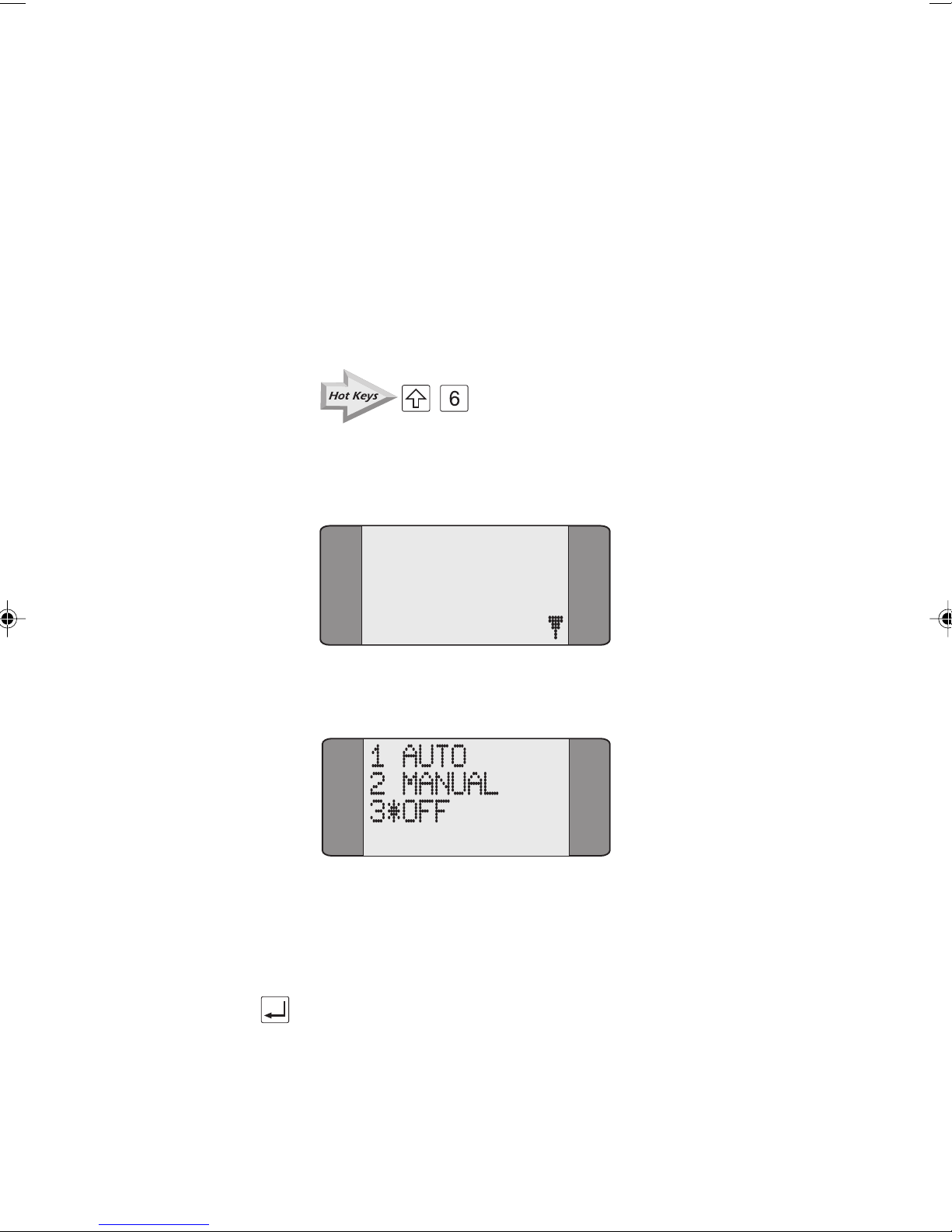
The Loop options are as follows:
•
AUTO: Call Screening is operational, irrespective of the
Setting up your AuroraPlus
service type. Please refer to Call Screening in this
chapter for further details. Successfully screened
incoming calls are answered automatically and a loop
connected. Use this setting for voice or data calls when
you wish to perform a looped-back BER Test with a
remote device. Note that the unit may be left
unattended in this mode. Connect the charger unless
AuroraPlus is line powered.
• MANUAL: Incoming calls are answered manually and
then a loop is connected. Use this setting for voice or
data calls when you wish to perform a looped-back
BER Test with a remote device. Service Checking for
outgoing calls operates normally. Call Screening can
only be used with voice (i.e. speech or 3k1). Screening
only operates if you selected
TELCHK from the CALLS
menu.
Issue 5 - 04/01 3-3
Page 54
Trend AuroraPlus User Guide
• OFF: Incoming calls are answered manually and then
connected to the microphone and earpiece. This setting
is normally used for voice calls. Service Checking for
outgoing calls operates normally, but Call Screening can
only be used with voice calls (i.e. speech or 3k1).
Screening only operates if you selected
CALLS menu.
the
Changing the Loop Options
+
Choose ISDN from the Setup menu to display the following
screen:
1 PROTOCOL
2 LINE TYPE
3 LOOP
4 CALL SCRN
Choose LOOP. The loop options are displayed.
TELCHK from
Choose the appropriate option. An asterisk (*) symbol is
displayed against the current selection. The above example
shows
Press ENTER to save your selection. You return to the
previous screen.
3-4 429850
OFF selected.
Page 55
Call Screening
AuroraPlus lets you set screening options for incoming calls.
When enabled, screening allows only incoming calls with a
specified Called Party Number (CPN) or Calling Line Identity
(CLI). You can store one CPN and one CLI number for Call
Screening.
For example, if your number is 123456 you may wish to enter
CPN SCRN of 12345. This ensures that only incoming calls
a
with these first five digits are accepted.
Choose ISDN from the Setup menu.
Select
Setting up your AuroraPlus
CALL SCRN.
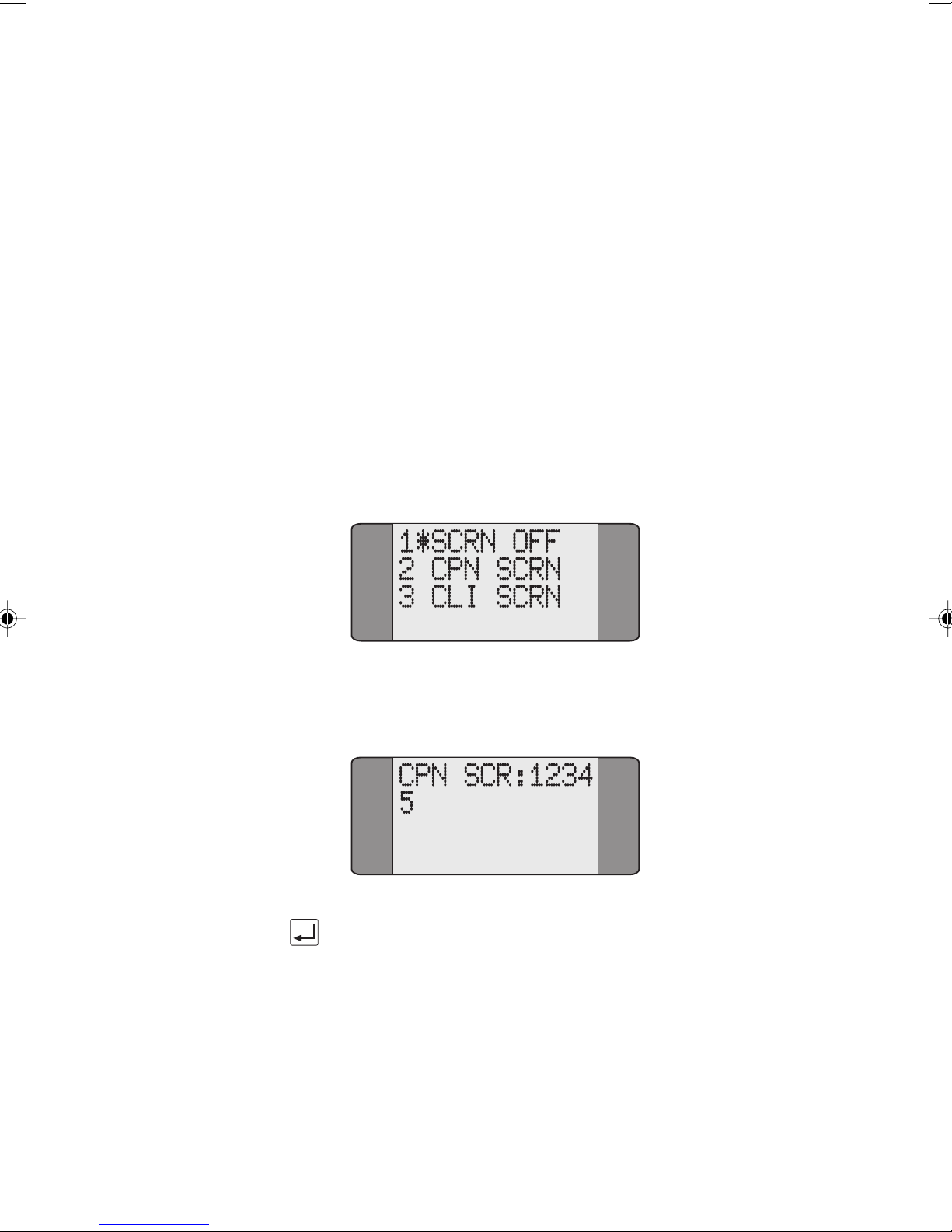
Choose either CPN SCRN or CLI SCRN. An asterisk is displayed
against your last selection.
Input the new number (this overwrites any existing values) and
press ENTER to save it.
Issue 5 - 04/01 3-5
Page 56

Trend AuroraPlus User Guide
To disable Call Screening, choose SCRN OFF.
Notes
• To erase one digit at a time press the CLEAR key.
• To append a Sub-address to the CPN or CLI, add a
slash symbol (/) by pressing
Sub-address.
+ followed by the
Address Setup: Setting CPN Sub-address &
CLI
Three types of addresses can be stored in AuroraPlus:
• your own Calling Line Identification (CLI) number.
ISDN lines using the ETSI protocol may be addressed
with several different subscriber numbers. On
Point-to-Multipoint lines this feature is called MSN
(Multiple Subscriber Number). The numbers are
referred to as MSN1, MSN2 etc. On Point-to-Point
lines this feature is called DDI (Direct Dialling
Inward).
• your own Sub-address — Calling Party Sub-address
(CLI-SUB)
• a Called Party Sub-address (CPN-SUB)
These addresses can be stored in addition to outgoing
directory numbers for speed dialling.
AuroraPlus sends CLI and CLI-SUB in the outgoing SETUP
message to the switching system to identify itself.
The Called Party Sub-address (CPN-SUB) is included in an
outgoing SETUP
Choose
3-6 429850
ISDN from the Setup menu.
message only if En Bloc dialling is used.
Page 57
Setting up your AuroraPlus
Press SCROLL, then choose ADDRESS to display the
following screen:
1 CPN SUB
2 CLI
3 CUG
Select the appropriate option. An address entry screen is
displayed, depending on your selection.
Inputting a CPN Sub-address or CLI
Enter or overwrite the number you want to store. This
number may be up to 19 digits in length.
You can enter CPN Sub-address and CLI Sub-addresses.
Sub-addresses are separated from the main number by a slash
/) symbol. This symbol is produced by pressing SHIFT+
(
asterisk (
Press the ENTER key. AuroraPlus saves the number and
returns to the previous menu.
*) - + .
Notes
• To clear a previously stored number, press the CLEAR
key to erase one digit at a time.
Address Setup: Setting CLI Presentation/
Restriction
Calling Line ID Presentation (CLIP) enables a subscriber
receiving a call to display the caller's ISDN number. The
service operates even when the subscriber's line is busy.
Issue 5 - 04/01 3-7
Calling Line ID Restriction (CLIR) allows a subscriber
making a call to choose whether or not their ISDN number is
presented to the person they are calling.
Page 58
Trend AuroraPlus User Guide
Choose ISDN from the SETUP menu.
Press SCROLL, then choose ADDRESS to display the
following screen.
1 CPN SUB
2 CLI
3 CUG
Choose CLI.
A screen similar to the following is displayed.
CLI:A-
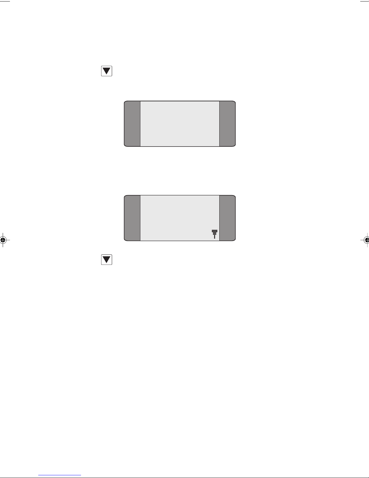
Press SCROLL, to display the following Presentation
Indication options. You can enter up to 20 digits in each
option.
_ _ Not Present. Removes the Presentation
Indicator from the CLI information
element.
A Presentation Allowed. Allows presentation
of the CLI or COL to the called party.
R Presentation Restricted. Does not allow
presentation of the CLI or COL to the
called party.
I Interworking. Enables you to confirm that
the remote terminal does not display the
CLI when the call is routed through two
3-8 429850
noncompliant networks.
Page 59
Setting up your AuroraPlus
U Reserved. Included for future development.
Press ENTER ( ) to confirm your choice.
Setting up a CUG (Closed User Group)
A Closed User Group is a group of subscribers on a network
that are configured so that calls to and from the group can be
restricted.
Choose
Press SCROLL, then choose ADDRESS to display the
following screen.
ISDN from the SETUP menu.
1 CPN SUB
2 CLI
3 CUG
Choose CUG to display the following screen.
1 CUG:None
2 ACCESS:NO
Issue 5 - 04/01 3-9
Choose CUG.
CUG:32700
0..32767
CLEAR = None
Page 60
Trend AuroraPlus User Guide
Enter the CUG you want to use.
To delete digits one at a time, press CLEAR. If you want to
enter a new CUG, enter the first digit to delete the current
CUG.
Setting up the CUG Access restrictions
This option enables you to set up whether you want to be
able to make calls outside the CUG, or restrict the calls to
inside the CUG.
From the
CUG screen choose ACCESS.
1 CUG:None
2 ACCESS:NO
Choose YES to allow calls to be made outside the CUG.
Choose
Setting the BER Test Length
The BER (Bit Error Rate) Test is used to check the integrity
of an ISDN line. A call may be made to the number of the
other B Channel on the calling unit, a loopback box or to
another remote tester.
NO to restrict calls to within the CUG.
When you are performing a BER test you can make a
self-call,
the other B-Channel.
If two AuroraPlus units are connected, and if the Loop option
is set to
by answering the call in the BERT menu. Note that if you do
this the BER test that finishes last will have logged more
errors than the test that finished first.
3-10 429850
AuroraPlus then automatically loops the call back on
OFF, the call may be turned into a two-way BER Test
Page 61
The call uses the currently selected service. The BER Test is
performed using a 2047 bit Pseudo Random pattern
according to ITU G.821/O.152.
Note
Your settings will also apply to the fixed link BERT. For
more information, see Testing Fixed Links in Chapter 5.
Choose BERT from the Setup menu to display a list of preset
durations.
Setting up your AuroraPlus
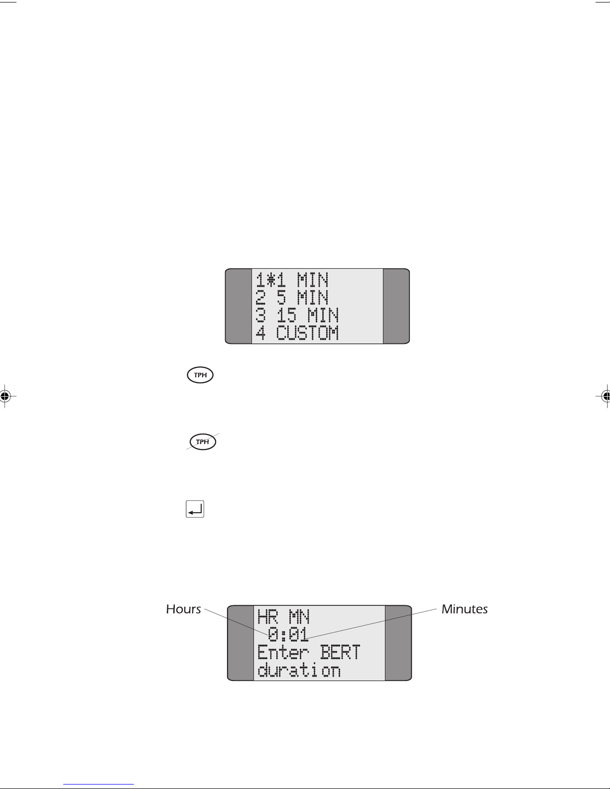
You can select from the following durations - 1 MIN, 5 MIN
or 30 MIN. An asterisk (*) is displayed next to the current
selection. The default duration is 5 minutes.
You can select from the following durations - 1 MIN, 5 MIN
or 15 MIN. An asterisk (*) is displayed next to the current
selection. The default duration is 1 minute.
Press the ENTER key to confirm your choice. AuroraPlus
returns to the previous menu.
To specify a different duration for the BER Test, choose
CUSTOM. This displays the following screen:
Issue 5 - 04/01 3-11
Page 62
Trend AuroraPlus User Guide
Specify the duration of the BERT, using the number keys to
enter the time in hours and minutes, and then press ENTER.
For a continuous BER Test, enter a value of zeroes.
Note
The maximum length of time you can define for a custom
BERT is 3hrs 59min.
Tracer Setup
The Tracer is the name given to the function which lets you
capture ISDN signalling information from the D (Demand)
Channel during an attempted or established call. This
information is sometimes called 'Decode'.
The stored information is held in
AuroraPlus lets you review the stored data on screen or
download it to a PC for analysis. You can also clear the data
from memory. The following section describes the capture of
decode to memory. You can store up to 99 lines of decode in
AuroraPlus's memory.
TRACER from the Setup menu.
Select
AuroraPlus's memory.
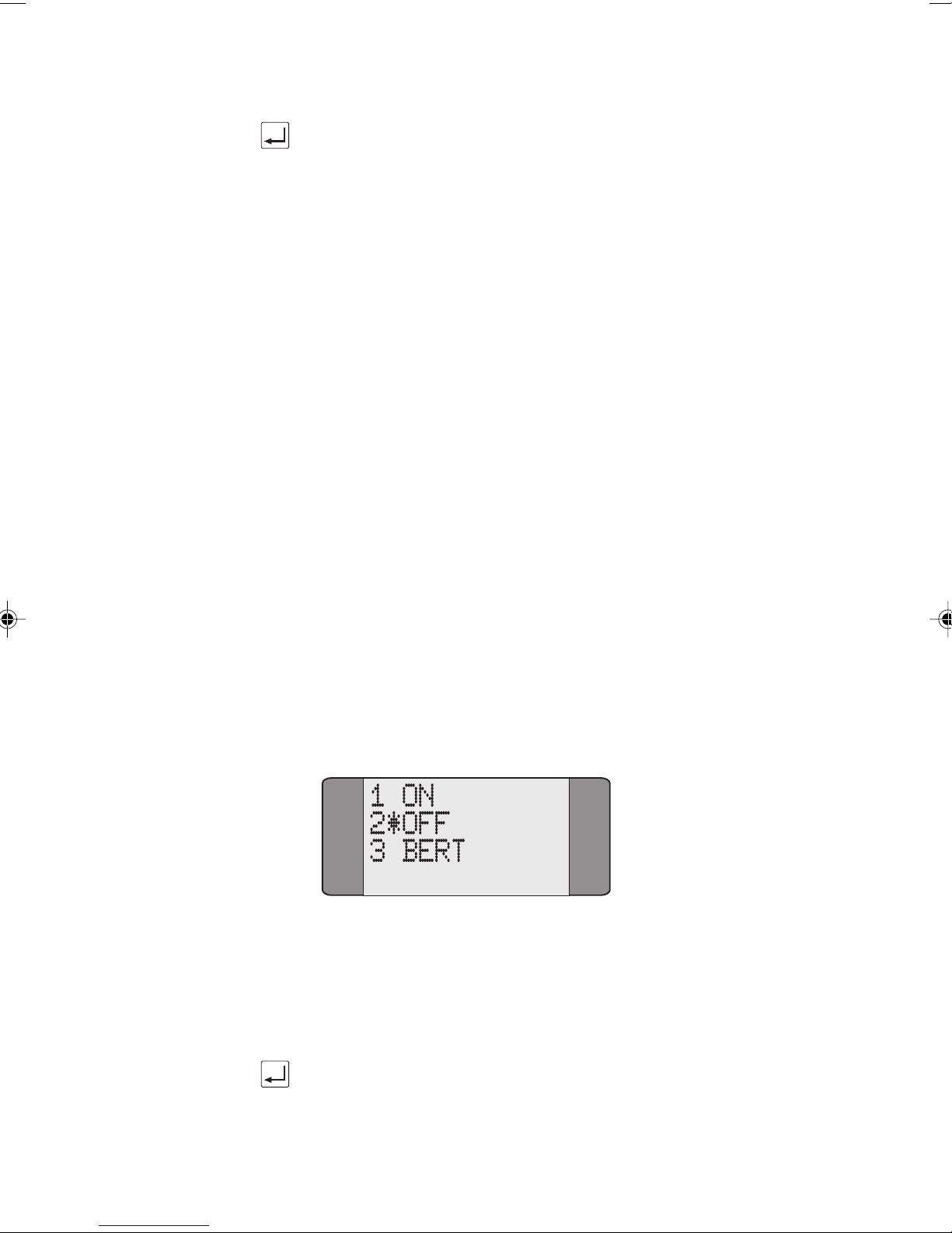
Turning the Tracer On and Off
Choose ON to start capturing data; choose OFF to stop data
capture. An asterisk (
current selection.
Press the ENTER key to confirm your choice.
3-12 429850
*) symbol is displayed next to the
Page 63
Setting up your AuroraPlus
After turning the Tracer on, continue with normal operation
(making calls etc.)
becomes full and
Press CLEAR to exit the Buffer Full Screen.
You can download the trace to a PC running the Trend
AuroraExpert for Windows data analysis package. For
information on downloading the tracer memory to a PC, see
Displaying Tracer Output in Chapter 5.
AuroraPlus captures data until the memory
Buffer Full is displayed.
Entering the Date and Time
Note
If you switch off AuroraPlus the date and time is not updated
while it is switched off, it remains the same as when you
switched it off. The date and time will be lost if the battery
or external power supply fails.
Choose
GENERAL from the SETUP menu.
1 LANGUAGE
2 LOUDSPKR
3 DATE/TIME
4 SELFTEST
Choose DATE/TIME.
DATE:
01/01/1970
TIME:
00:00:12
Press SCROLL to select TIME or DATE.
Enter your settings and press ENTER to save and return to
Issue 5 - 04/01 3-13
GENERAL screen.
the
Page 64
Trend AuroraPlus User Guide
Storing Speed Dialling Numbers
Speed Dialling lets you recall and dial previously stored
numbers from
(numbers 0 to 4) may be stored - these may be numbers you
use regularly during testing. For details on how to make calls
using Speed Dialling, please refer to Speed Dialling in
Chapter 4.
Note
You can only use speed dial numbers when AuroraPlus is
operating in En-Bloc dialling mode.
Choose DIRECTORY from the General menu to display the
following Speed Dial Screen. By default,
the contents of the first memory location.
AuroraPlus's memory. Up to five numbers
AuroraPlus displays
Displaying a Different Memory Location
Press the SHIFT key followed by the appropriate number
key to select a different memory location. For example, to
select memory location 2, press SHIFT and 2. The following
screen is displayed:
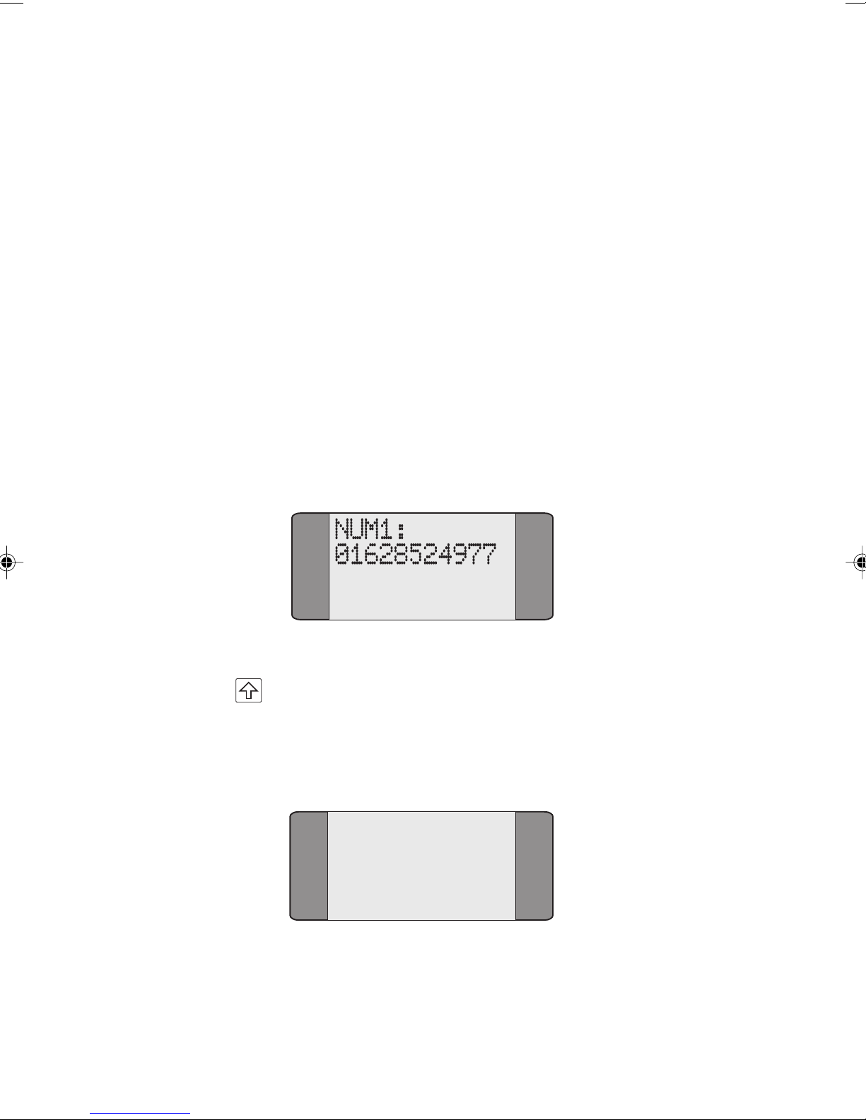
NUM2:
0158065118
3-14 429850
Page 65
Setting up your AuroraPlus
Entering a Speed Dial Number
If a number is already stored in this location RECALL is
displayed, together with the number held.
To add digits to the end of the existing number press CLEAR
and enter the new digits.
To erase the existing number, digit by digit, repeatedly press
the CLEAR key.
After inputting the number, press ENTER to save it. A
screen similar to the following is displayed to indicate the
number has been stored:
NUM3:
01268819408
STORED
Changing the Language
AuroraPlus is designed to display text in up to four languages.
The languages currently available are English, French,
Spanish, Italian and German.
Choose
similar to the following:
GENERAL from the Setup menu to display a screen
1 LANGUAGE
2 LOUDSPKR
3 DATE/TIME
4 SELFTEST
Issue 5 - 04/01 3-15
Page 66
Trend AuroraPlus User Guide
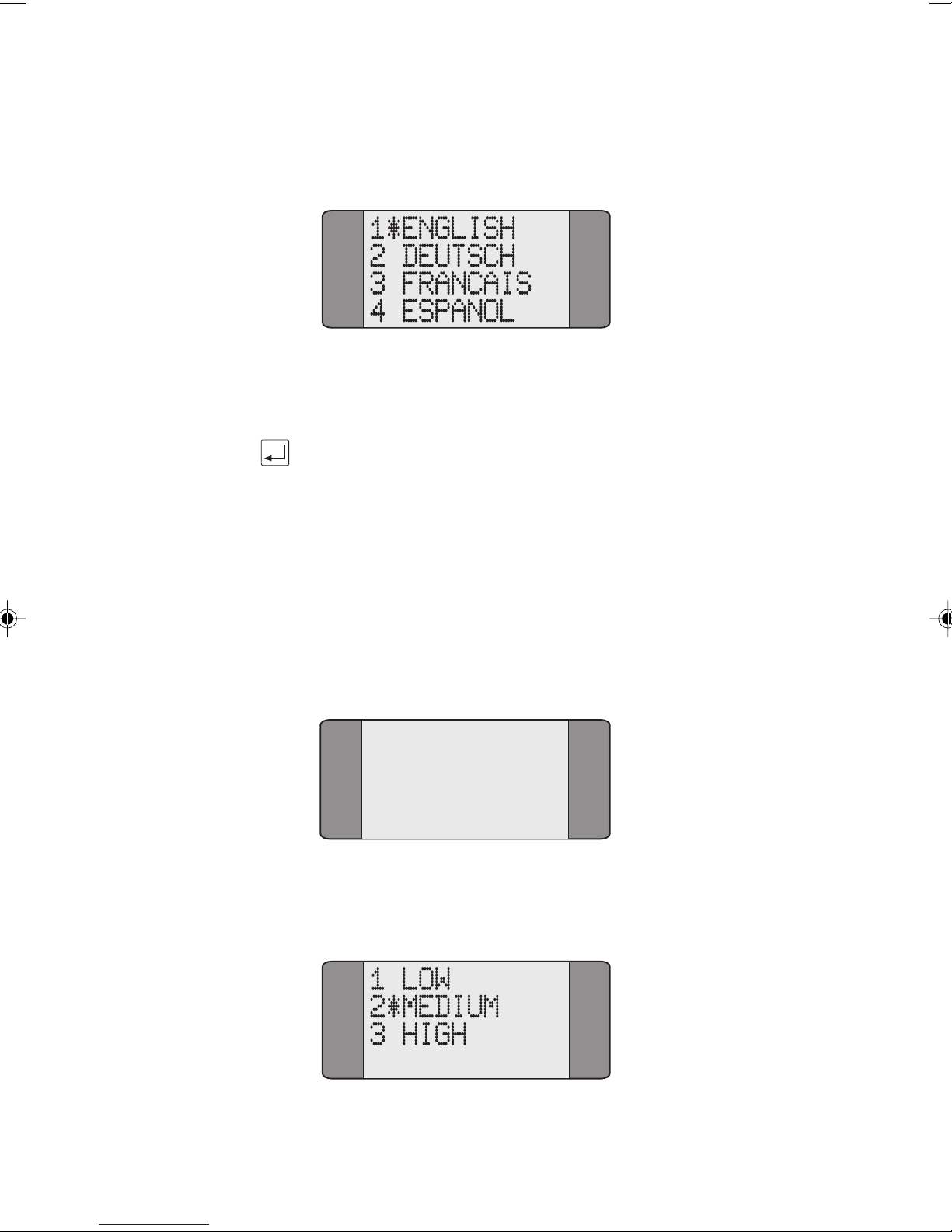
Choose LANGUAGE from the General menu to display a screen
similar to the following:
Select a language from the display. An asterisk (*) appears
next to the current selection.
Press the ENTER key to confirm your choice.
Loudspeaker Volume Settings
AuroraPlus contains a loudspeaker built into the top left hand
side, next to the earpiece. The level of volume obtainable
from the loudspeaker can be set at three levels as follows:
Choose
following screen:
GENERAL from the Setup menu to display the
1 LANGUAGE
2 LOUDSPKR
3 DATE/TIME
4 SELFTEST
Choose LOUDSPKR from the General menu to display the
following screen :
3-16 429850
Page 67
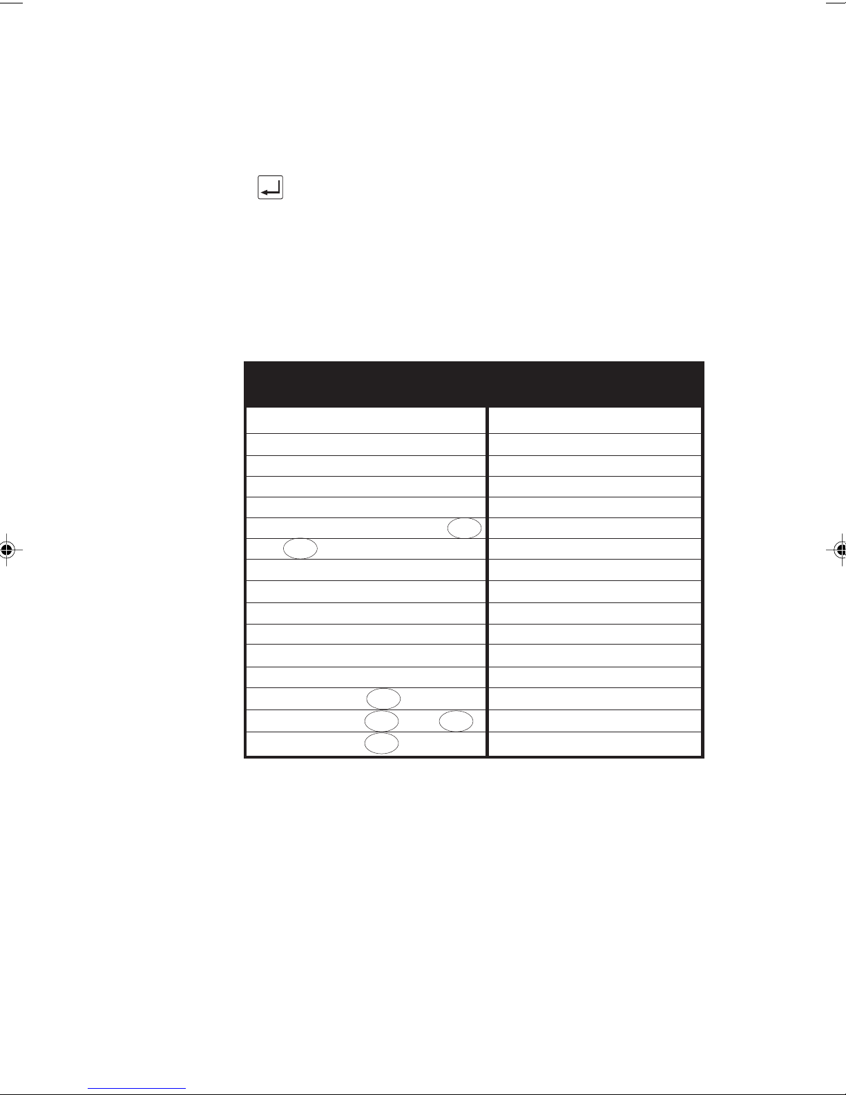
Choose the required level. An asterisk (*) appears next to the
current selection.
Press the ENTER key to confirm your choice.
Default Settings
The following table shows the factory default settings for
AuroraPlus. You can reset these defaults using Self Test Facility
code '13' - please refer to Self Test Functions in Chapter 5
for further information.
Protocol ETSI
Bus Configuration Point to Multipoint (PMP)
Service Type Telephony (ISDN-TEL)
B Channel Bx
Encoding A-law
Calling Line Identity (CLI) No Entry
1TR6
EAZ 0
CPN Sub-address No Entry
Call Redial No Entry
Speed Dialling No Entry
Call Screening Off
CPN Screening No Entry
CLI Screening No Entry
EAZ Screening 0
BERT Duration and 1 minute
BERT Duration 5 minute
Setting up your AuroraPlus
Factory Default Settings
ETSI
1TR6
ETSI
TPH
1TR6
Issue 5 - 04/01 3-17
Page 68

Trend AuroraPlus User Guide
3-18 429850
Page 69
Call Establishment
This chapter describes how to make and receive calls using
AuroraPlus. Also discussed is how to select an ISDN service
and bearer channel for calls and how to access the
supplementary services options.
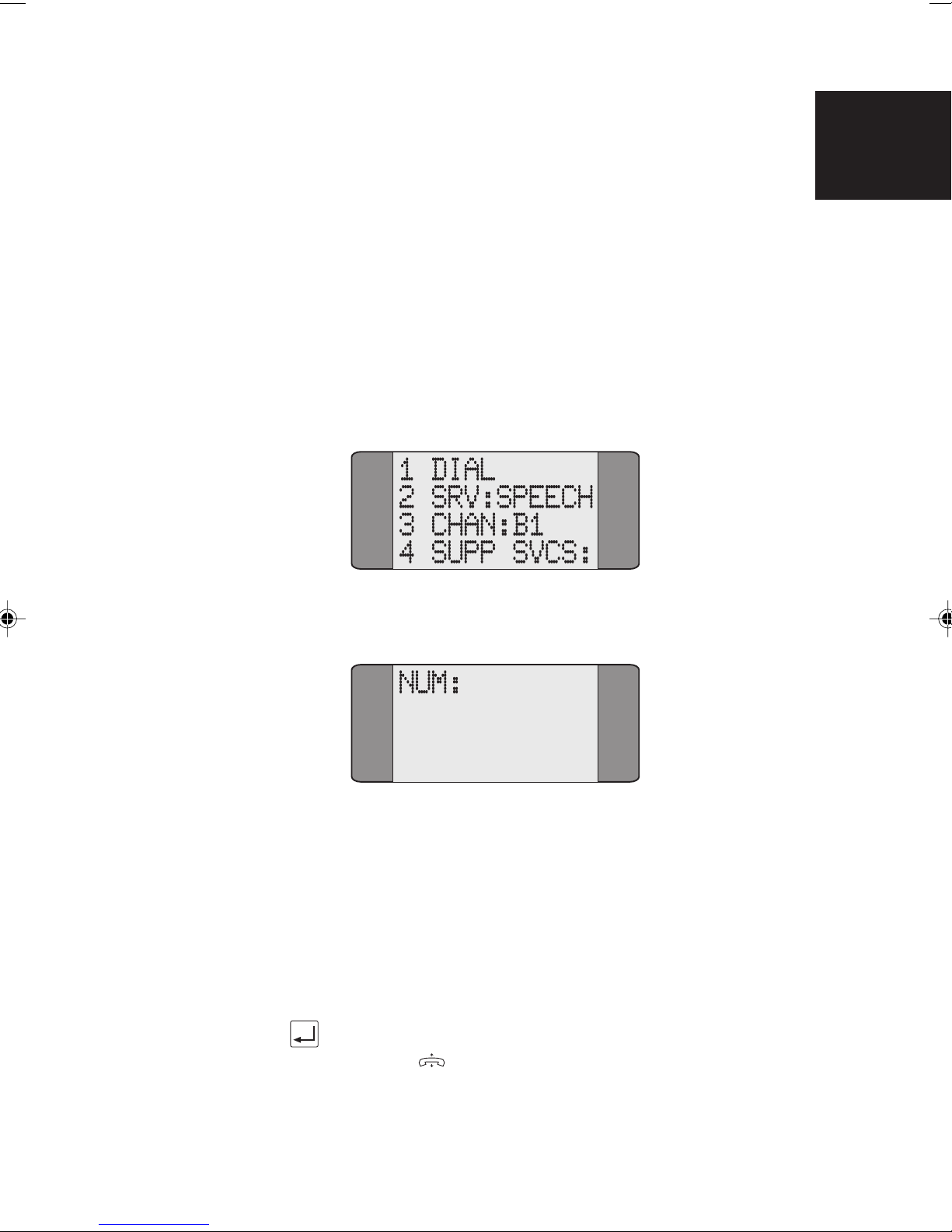
Making a Call
Choose CALLS from the Main Menu to display the following
screen:
Call Establishment
4
Dialling
Choose DIAL to display a dial screen.
AuroraPlus can make calls in either the Overlap or En Bloc
dialling mode. En Bloc dialling involves entering the entire
number before it is sent. With Overlap dialling, digits are
sent as they are dialled.
En Bloc Dialling
Enter the entire number you want to dial and press the
ENTER (
) key.
Issue 5 - 04/01 4-1
Page 70
Trend AuroraPlus User Guide
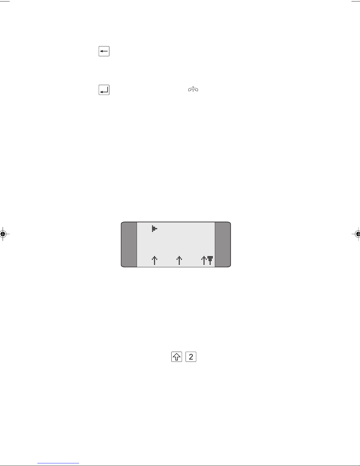
If you make a mistake, press the CLEAR key to erase the last
digit entered.
Overlap Dialling
• Press the ENTER ( ) key before entering the CPN.
Note that the screen may display
depending on the network.
• Enter the digits you want to dial.
Note
If the call is being established on a fixed link (no protocol),
or back to back with another tester it connects before any
digits are dialled.
PROCEEDING,
The call is initiated and
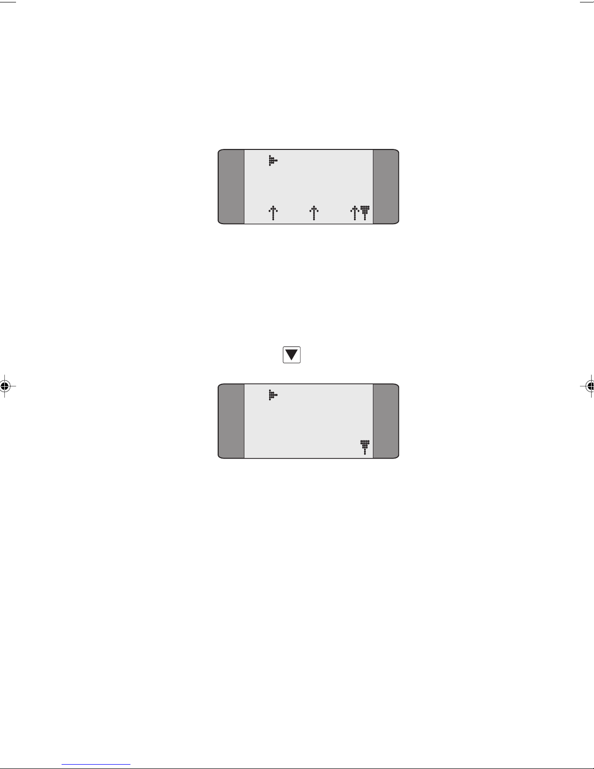
screen, similar to the following:
AuroraPlus displays a Call Status
B1 RINGBACK
SPEECH
L1 L2 L3
This shows the progress of the call, the number dialled, the
status of the layers and any messages received from the
network. For a speech call, the call progress tones are present
in either the earpiece or the loudspeaker.
When a speech call is connected, to switch on the
loudspeaker press
+ . If you make another call
without switching off
automatically switched on for that call.
4-2 429850
AuroraPlus the loudspeaker will be
Page 71
Call Establishment
Connected screen & Call Control Options
When the called party lifts the handset the call is connected
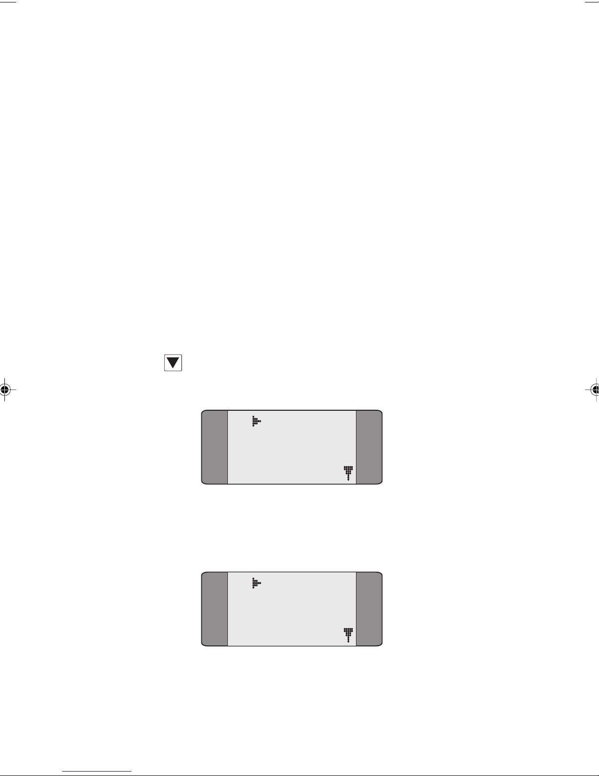
and a screen similar to the following is displayed:
B1 CONNECT
SPEECH
L1 L2 L3
In the above example, a call has been connected on channel
B1.
Once a call is connected, the following options are available:
running a BER Test, activating a Loop, or selecting a
Supplementary Service. To access these options, press the
SCROLL key
to see the Call Control Options screen:
B1 CONNECT
1 BERT
2 LOOP
3 SUPP SVCS
To perform a BER Test, choose BERT - the BER Test Status
screen is displayed. See Performing a BER Test in Chapter 5
for more information.
To activate a Loop, choose
screen is displayed. See Setting Up a Loop in Chapter 3 for
more information.
To select a Supplementary Service, choose
LOOP - the Loop Activation
SUPP SVCS - you
Issue 5 - 04/01 4-3
can choose either the
SRV 3
options. See Supplementary Service Selection later in
this chapter.
KEYPAD, HOLD, SUSPEND, UUI, or UUS3
Page 72
Trend AuroraPlus User Guide
To send DTMF tones, choose TONES.
Note
Once in the connected state, additional Called Party Number
digits are sent in the D Channel each time a number key is
pressed. This is necessary to 'dial through' certain PBX
equipment. Some ISDN equipment may not respond correctly
to this signalling. When connected to such equipment, be
careful not to send digits, which may result in the call entering
an indeterminate state.
DTMF tones
When a call is connected DTMF tones are not sent
automatically.
To send DTMF tones when a call is connected
From the Connect Screen press SCROLL to display the
following screen.
B1 CONNECT
4 TONE
Choose TONE.
Enter the digits you want to send.
B1 TONE
123456789012
3456
4-4 429850
Page 73
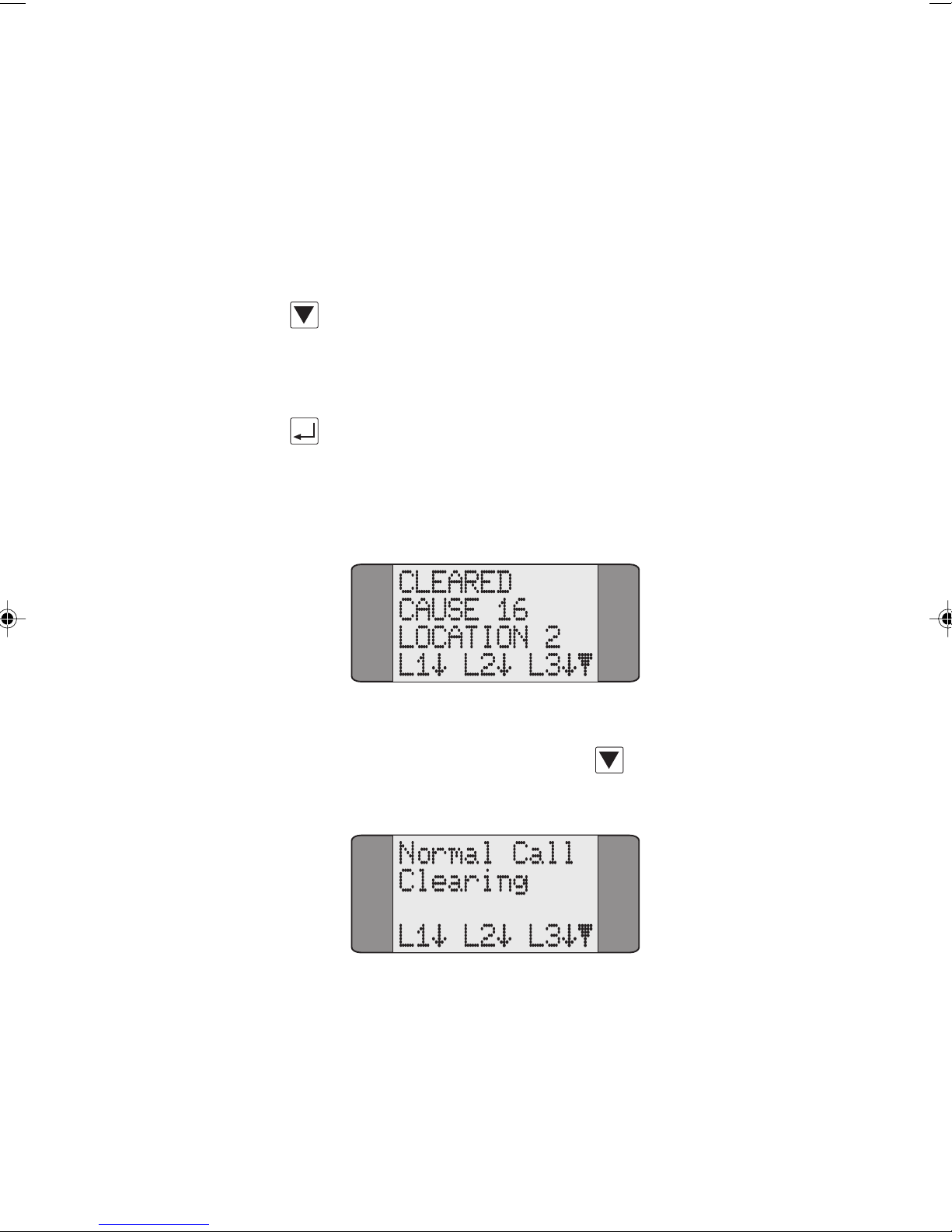
The DTMF tone is sent as you enter each digit. Digits are
deleted from the beginning of the display if you enter more
than 35 digits. If you continue to add more digits the new
digits are added to the end of the display.
If you want to delete all the digits displayed, press CLEAR.
Press SCROLL and choose EXIT to return to the CONNECT
menu.
Clearing a Call
Press ENTER to clear a call. AuroraPlus displays a Released (if
Call Establishment
cleared remotely) or
Cleared screen similar to the one shown
below. This displays the Call Clearing Cause Code, the
location and Layer Status information.
To display an explanation of the various Cause Codes and
locations, press the SCROLL key
. For further
information, see Appendix 4 Call Clearing Cause Codes.
Issue 5 - 04/01 4-5
Page 74
Trend AuroraPlus User Guide
Speed Dialling
Speed dialling only operates in En Bloc dialling mode. Please
refer to Storing Speed Dialling Numbers in Chapter 3 for
information on setting up this facility.
Choose
CALLS/DIAL from the Main Menu to display a Dial
screen.
Press SHIFT followed by the number of the memory
location containing the CPN you wish to dial. For example,
to dial the number held in Speed Dial memory location 1,
press
+ 1. The number is recalled from memory and
displayed:
Press ENTER ( ) to dial the number.
Call Redial
This facility lets you automatically redial the last number
dialled. The last number dialled is stored in memory after the
unit is disconnected from the ISDN for as long as the power
is on. Redial operates in En Bloc and Overlap dialling modes.
CALLS/DIAL to display the Dial screen together with
Select
the last number dialled.
4-6 429850
Page 75
Press ENTER to automatically redial this number. If you do
not want to redial this number, enter a different number; the
last number dialled is overwritten.
To add digits to the end of the last number dialled, press the
CLEAR key once and enter the new digits.
To erase the last number dialled, digit by digit, repeatedly
press the CLEAR key.
Note
If you alter the service or channel settings, the last number
dialled is automatically cleared and Call Redial is not
available.
Call Establishment
Answering Incoming Calls
How an incoming call is answered depends on the Loop
settings. If the Loop option is set to
automatically answers incoming calls. If it is set to OFF or
MANUAL, you have to answer the call manually. Please refer to
Setting up a Loop in Chapter 3 for further information.
An incoming call is indicated by the ringer sounding. If it is
the only active call it is displayed on the screen immediately.
+ If there are other active calls press SHIFT + 4 (B Channel
selection). A screen similar to the following is displayed:
B1 CALL
SPEECH
L1 L2 L3
AUTO, AuroraPlus
Issue 5 - 04/01 4-7
Accepting the call
Press the ENTER ( ) key to answer the incoming call.
Page 76
Trend AuroraPlus User Guide
Note
If an incoming call is received when you are in a Setup or
Results screen it is automatically rejected by
Call Waiting
Call Waiting informs you that there is an incoming call, even
when no channel is available to accept it because other calls
are in progress.
can either accept or reject the waiting call.
Dealing with a Second Call
Call Waiting depends on the Loop settings. If the Loop
option is set to
automatically answers any new, incoming calls. If it is set to
OFF or MANUAL, a second incoming call is indicated by a
'beep' in the earpiece or loudspeaker. Please refer to Setting
up a Loop in Chapter 3 for further information.
AuroraPlus beeps to indicate Call Waiting - you
AUTO and a B Channel is available, AuroraPlus
AuroraPlus.
Note
If an incoming call arrives on the second B Channel during
the dialling procedure, the dialling procedure is terminated
and the Call Waiting procedure starts.
CALL WAITING is displayed on a screen similar to the one
shown below. The B Channel, Bearer Service, CLI and Layer
Status are also displayed.
B2 CONNECT
SPEECH
L1 L2 L3
4-8 429850
Page 77
Call Establishment
To answer the new call manually you must either clear the
original call or place it on hold. For details, refer to Placing a
Call on Hold and Clearing a Call, in this chapter.
Dealing with a third call
If there is an incoming call when both B Channels are in use
you can put one of the other calls on hold while you answer
the new incoming call. A new incoming call is indicated by a
'beep' in the earpiece or loudspeaker.
To answer the new incoming call:
+ Move to the new incoming call by pressing SHIFT + 4.
B0 CALL
3.1K
L1 L2 L3
Press the ENTER ( ) key to answer the incoming call and
put the last active call on hold.
Placing a Call on Hold
During an existing call, you can either:
• put the current call on hold and make an outgoing call
or
• accept a second incoming call.
Making an Outgoing Call During an Existing Call
Press the SCROLL key from the Connected screen to display
the Call Control Options screen:
Issue 5 - 04/01 4-9
B1 CONNECT
1 BERT
2 LOOP
3 SUPP SVCS
Page 78
Trend AuroraPlus User Guide
Select SUPP SVCS.
B1 CONNECT
1 KEYPAD
2 HOLD
3 SUSPEND
Select HOLD. This places the current call on hold and HELD is
displayed in the Call Status screen.
B1 HELD
SPEECH
Note
If the Call Hold request fails, REJECT is displayed. Press
CLEAR to return to the Connected screen of the established
call.
Press SCROLL to display further options:
Choose NEW CALL to make a new, outgoing call.
L1 L2 L3
B1 HELD
1 RETRIEVE
2 NEW CALL
4-10 429850
Page 79
Call Establishment
Retrieving the held call
First, press ENTER to clear down the second call.
Press SCROLL from the Call Status screen of the original
call to display further options.
Choose RETRIEVE to recover the held call.
Accepting an Incoming Call During an Existing Call
If a second call is received, during an existing call, AuroraPlus
beeps to indicate there is a call waiting. You can place the
current call on hold and answer the second call.
B1 CONNECT
3.1K
L1 L2 L3
Press SCROLL to display the Call Control Options. Choose
SUPP SVCS/HOLD - the existing call is placed on hold.
B1 HELD
SPEECH
L1 L2 L3
+ AuroraPlus rings to indicate the second call. Press SHIFT + 4
to display the Call Status screen for this call.
Issue 5 - 04/01 4-11
B2 CALL
3.1K
L1 L2 L3
Page 80
Trend AuroraPlus User Guide
To answer the second call, press ENTER ( ). The call is
connected.
B2 CONNECT
3.1K
L1 L2 L3
Retrieving the held call
First, press ENTER to clear down the second call.
+ Press SHIFT + 4 to display the Call Status screen for the held
call.
B1 CONNECT
3.1K
L1 L2 L3
Press SCROLL to display further options.
Choose
Tip
+ To toggle between the Call Status screens for each call, press
SHIFT and 4. The Call Status screen displays the channel and
CLI for each call.
Selecting an ISDN Service
This section describes how to select the teleservice capability
and service for any outgoing calls that you make.
RETRIEVE to recover the held call.
4-12 429850
Page 81
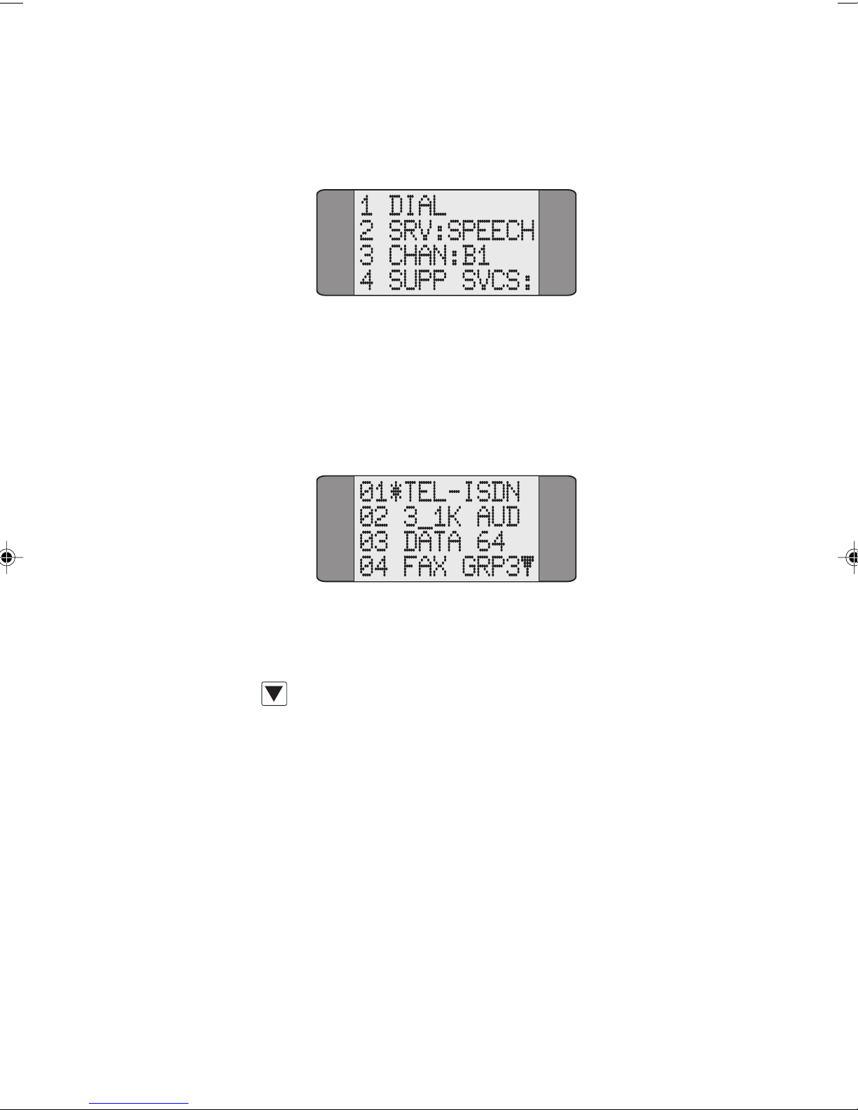
Call Establishment
Choose CALLS from the Main Menu to display the following
screen:
SRV: shows the currently selected service. In the above
example,
To change the service type, select
is the first of a set showing the services available:
An asterisk (*) is displayed against the currently selected
service.
Press the SCROLL key repeatedly to scroll through the
service screens.
To choose a service, input the number which corresponds to
SPEECH has been chosen.
SRV:. The following screen
Notes
Issue 5 - 04/01 4-13
it - for example, input 01 to select
selected and
the selected service type.
• You do not have to display the screen containing the
option you wish to select. Simply input the number
associated with it. For example, you may have options
01 to 04 displayed, but you can input and select 15
from this screen.
AuroraPlus displays the previous menu showing
TEL-ISDN. The service is
Page 82
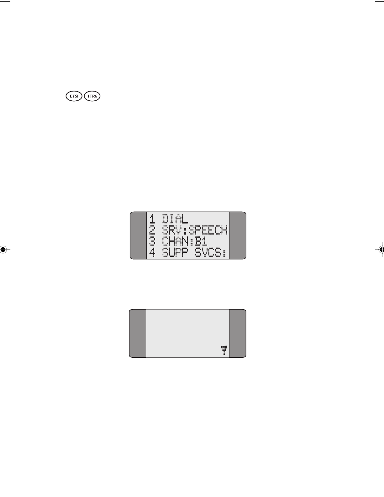
Trend AuroraPlus User Guide
• You must input two digits when selecting a service
type. For example, 01 for
TEL-ISDN.
Setting up a User-Defined Bearer Service
The user-defined Bearer Service enables you to define the
Bearer Capability, Low Layer Capability and High Level
Capability information elements sent in the SETUP message
at the start of a call.
To set up the Bearer Service:
Choose CALLS from the main menu to display the following
screen:
Choose SRV to display a screen similar to the following
screen.
01*T-ISDN
02 3_1K
03 DATA 64
04 FAX G3
4-14 429850
Page 83
Call Establishment
Press SCROLL to display more options and choose USER to
display the following screen.
USER DEF
1 BCAP
2 LLC
SIC:
1042
3 HLC
Tip
AuroraPlus stores the last option you selected.
Entering Hexadecimal Numbers
The Bearer Capability, Low Level Compatibility and High
Level Compatibility settings must be entered as hexadecimal
numbers. To enter the settings you want:
To enter the digits 1 to 9, press the appropriate keys.
To enter the digits A to C:
Repeatedly press 2 until the character you want is displayed.
To enter the digits D to F:
Repeatedly press 3 until the character you want is displayed.
To move the cursor to enter the next character press
SCROLL.
Issue 5 - 04/01 4-15
Page 84
Trend AuroraPlus User Guide
Setting the Bearer Capability
Choose BCAP to display the following screen.
BCAP
1A3462DE74
Enter the setting as described in Entering Hexadecimal
Numbers.
You can enter up to 11 bytes (22 characters).
You must enter an even number of characters.
Press ENTER ( ) to confirm your choice.
Setting the Low Layer Capability
Choose LLC to display the following screen.
LLC
1A3462
Enter the setting as described in Entering Hexadecimal
Numbers.
You can enter up to 14 bytes (28 characters).
You must enter an even number of characters.
Press ENTER ( ) to confirm your choice.
4-16 429850
Page 85
Setting the High Layer Capability
Choose HLC to display the following screen.
HLC
1A2C62
Enter the setting as described in Entering Hexadecimal
Numbers.
You can enter up to 3 bytes (6 characters).
You must enter an even number of characters.
Press ENTER ( ) to confirm your choice.
Call Establishment
Setting the Bearer Service
On the User Defined Bearer Capability screen, enter the
setting as described in Entering Hexadecimal Numbers.
You can enter up to 2 bytes (4 characters).
You must enter an even number of characters.
From the SRV screen choose USER to display the following
screen.
SIC:
1042
Press ENTER ( ) to confirm your choice.
Issue 5 - 04/01 4-17
Page 86
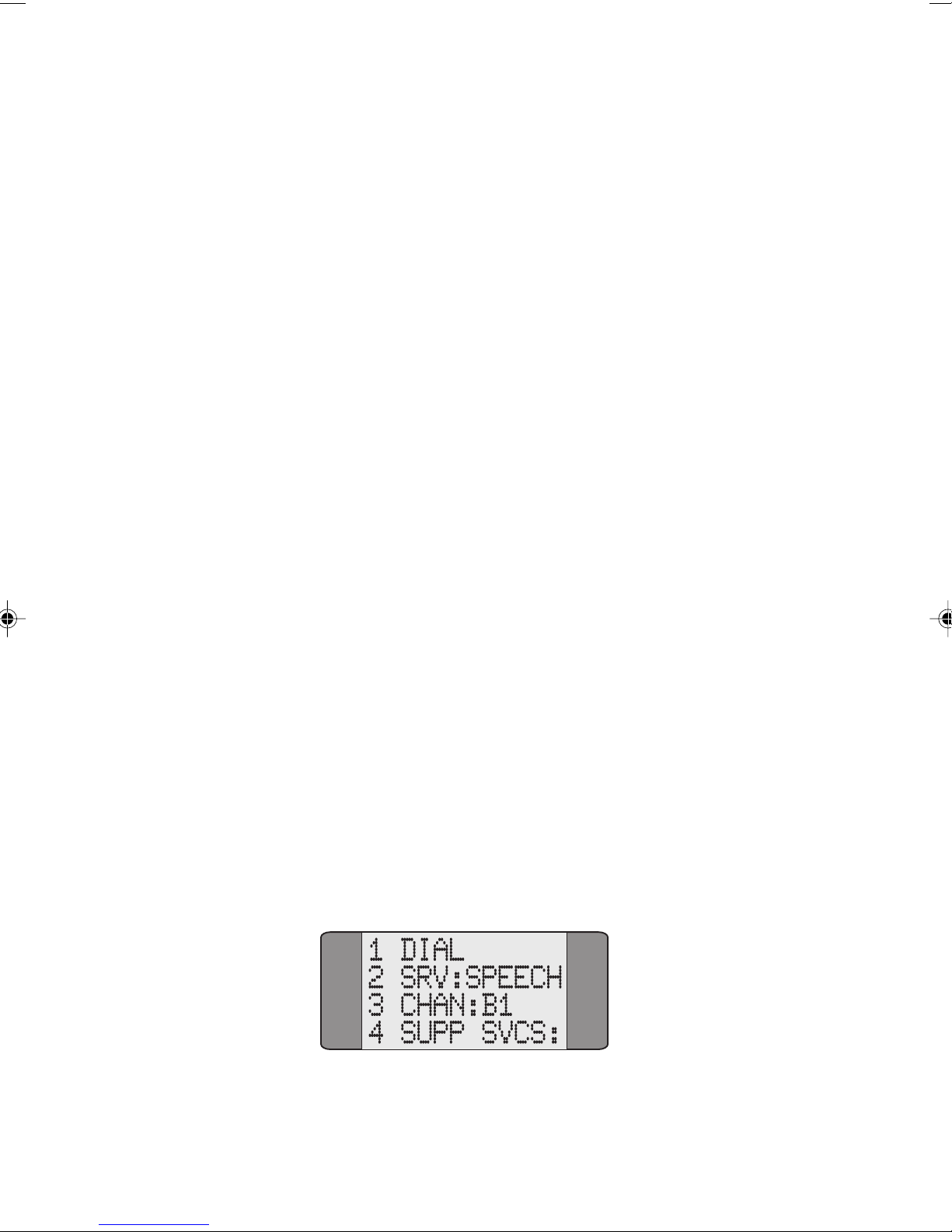
Trend AuroraPlus User Guide
Channel Setup
The ISDN Basic Rate Interface provides for two B Channels
(Bearer Channels) and one D Channel (Demand Channel).
Each multiplexed Bearer Channel can carry either voice or
data information. During setup, you should define the
default channel to make outgoing calls with as B1, B2 or BX.
The D Channel is a fixed physical link and is not definable.
The three channels are:
• B1 (Bearer Channel 1)
• B2 (Bearer Channel 2)
• BX (either Bearer Channel)
The type of services that each channel supports can also be
defined individually. For example, B1 can be set up for voice
communication, and B2 for fax. Where the channel or
service cannot be defined in advance (for example, a cleared
call on B1 with a maintained call on B2 when a subsequent
incoming call is received) then BX can be used to
automatically find the free channel.
Note
Some switches or PBXs do not allow the TE to 'demand' a B
Channel. The TE can only request a channel Bx.
Choose CALLS from the Main Menu to display the following
screen:
4-18 429850
Page 87
Call Establishment
CHAN: displays the currently selected channel - in the above
example Channel B1 has been chosen.
Choose CHAN: to change the currently selected channel. The
following screen is displayed:
1*B1
2B2
3BX
4D
Select the appropriate channel - B1, B2, BX or D. An asterisk
*) is displayed against the current selection. The previous
(
screen is displayed showing the channel selected.
Issue 5 - 04/01 4-19
Page 88

Trend AuroraPlus User Guide
Supplementary Service Selection
Supplementary Services are additional ISDN services to
which users can subscribe. They supplement the functions of
Bearer Services or Teleservices.
The available supplementary services are:
• Call Forwarding • Call Hold and Retrieve
• Call Deflection • Keypad
• Three Party Call • MCID
• CCBS • User-to-user signalling
• Call suspend/resume
Call Forwarding
Call Forwarding is a service which lets you send future
incoming calls to another number instead of to your number.
AuroraPlus can be used to activate and deactivate Call
Forwarding, where this facility is supported by the network.
Call Forwarding is protocol specific.
Types of Call Forwarding
• CFU (Call Forwarding Unconditional). This enables a
call to be forwarded regardless of the line status.
• CFB (Call Forwarding when Busy). This enables a call
to be forwarded when the line is in use.
• CFNR (Call Forwarding on No Reply). This only
forwards a call when the call is not answered.
Call Forwarding types may be applied individually to each
type of ISDN service or to all services. Call Forwarding is
also programmed individually for each CLI on a
Point-to-Multipoint configuration and for the whole
interface on a Point-to-Point configuration.
4-20 429850
Page 89
Call Establishment
Types of Call Forwarding
• AWS1 (Call Forwarding unconditional).
• AWS2 (Call Forwarding when there is no reply, when
the line is busy or when there is no Terminal
Equipment or the equipment is out of order).
The call screening on Call Forwarding is typically used where
the CPN has auto switched fax equipment and the Call
Forward number has not.
Types of Call Forwarding
Call Forwarding is either Unconditional or No Reply,
depending on which service has been subscribed to.
VN
Accessing Call Forwarding from the Menu
Choose CALLS from the Main Menu.
Choose
Service screen:
SUPP SVCS to display the following Supplementary
1 CALL FWD
2 KEYPAD
3 RESUME
Choose CALL FWD. AuroraPlus displays either:
VN
VN
Issue 5 - 04/01 4-21
• a screen for you to choose the Call Forwarding Type
• a screen from which you activate/deactivate Call
Forwarding.
Page 90
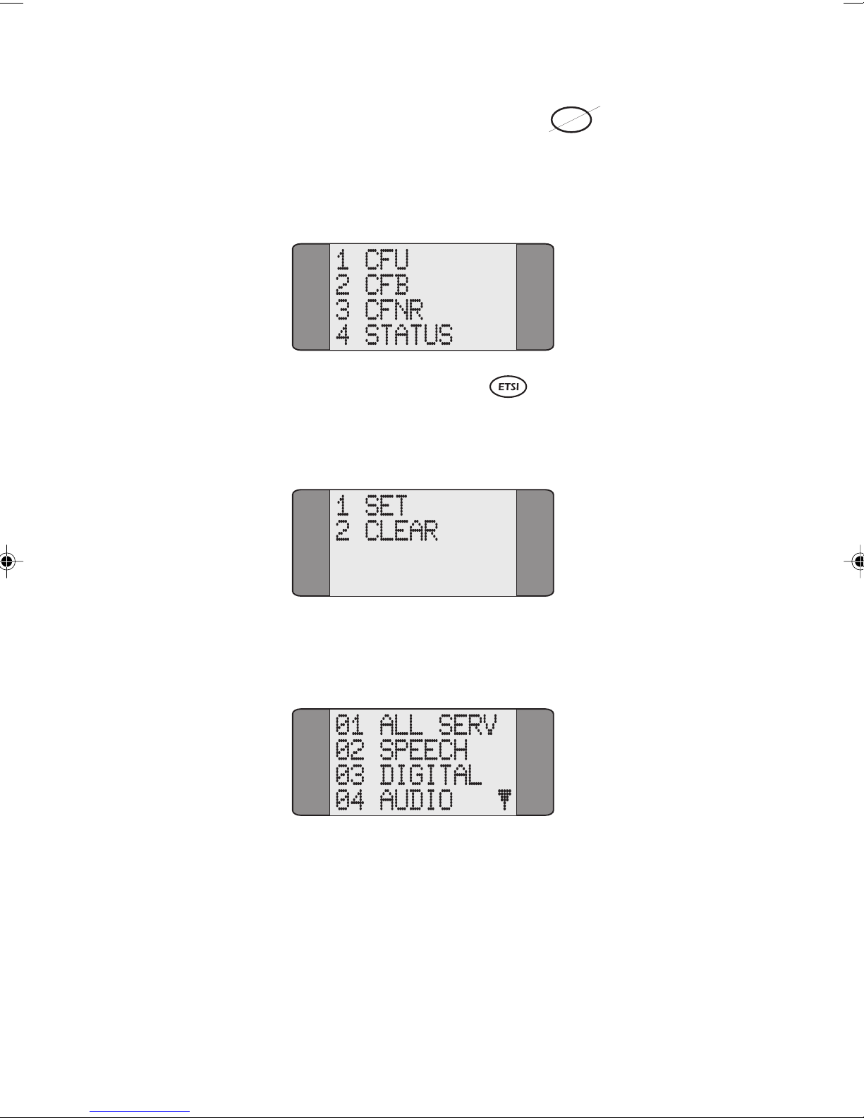
Trend AuroraPlus User Guide
VN
Selecting the Call Forwarding Type
Choose CALL FWD to display the Call Forwarding screen,
from which you select the Call Forwarding type. For
example:
Activating Call Forwarding
Select the Call Forwarding type you wish to activate. The
following screen is displayed:
Choose SET to activate Call Forwarding. Now select the
service type Call Forwarding is to be applied to.
4-22 429850
Page 91
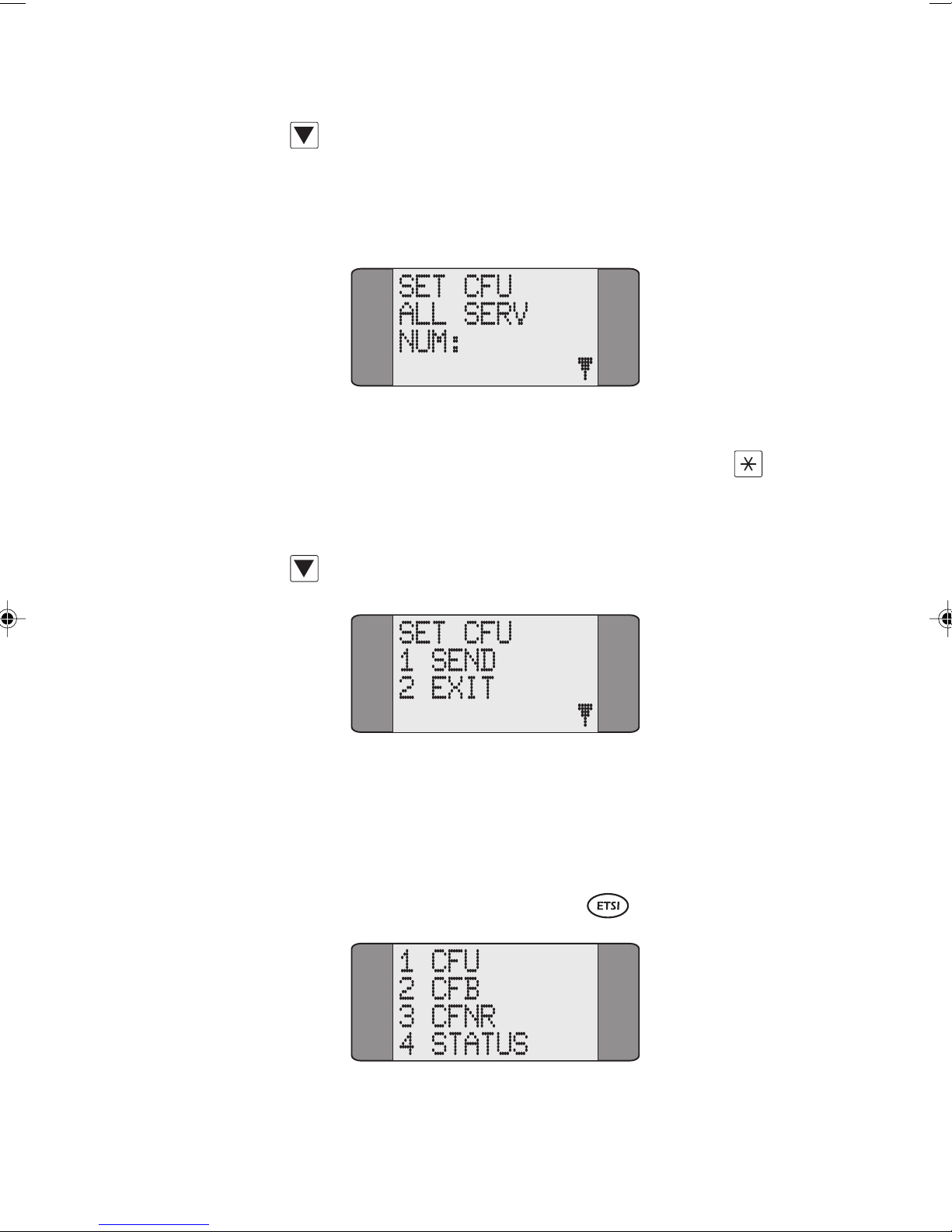
Call Establishment
Press the SCROLL key repeatedly to scroll through the
various service types. Enter a two digit service type code. If
you choose
ALL SERV Call Forwarding is applied to all
services. A screen similar to the following is displayed:
Key in the number to which calls are to be forwarded. You
can also enter a Sub-Address here - press SHIFT and
to
insert a Sub-Address delimiter and key in the Sub-Address
digits.
Press SCROLL to display the following screen:
Issue 5 - 04/01 4-23
Choose SEND to send the Call Forwarding request to the
network.
WAIT is displayed while AuroraPlus awaits an
acknowledgement from the network. Alternatively, choose
EXIT to return to the service type selection screens.
Deactivating Call Forwarding
Page 92
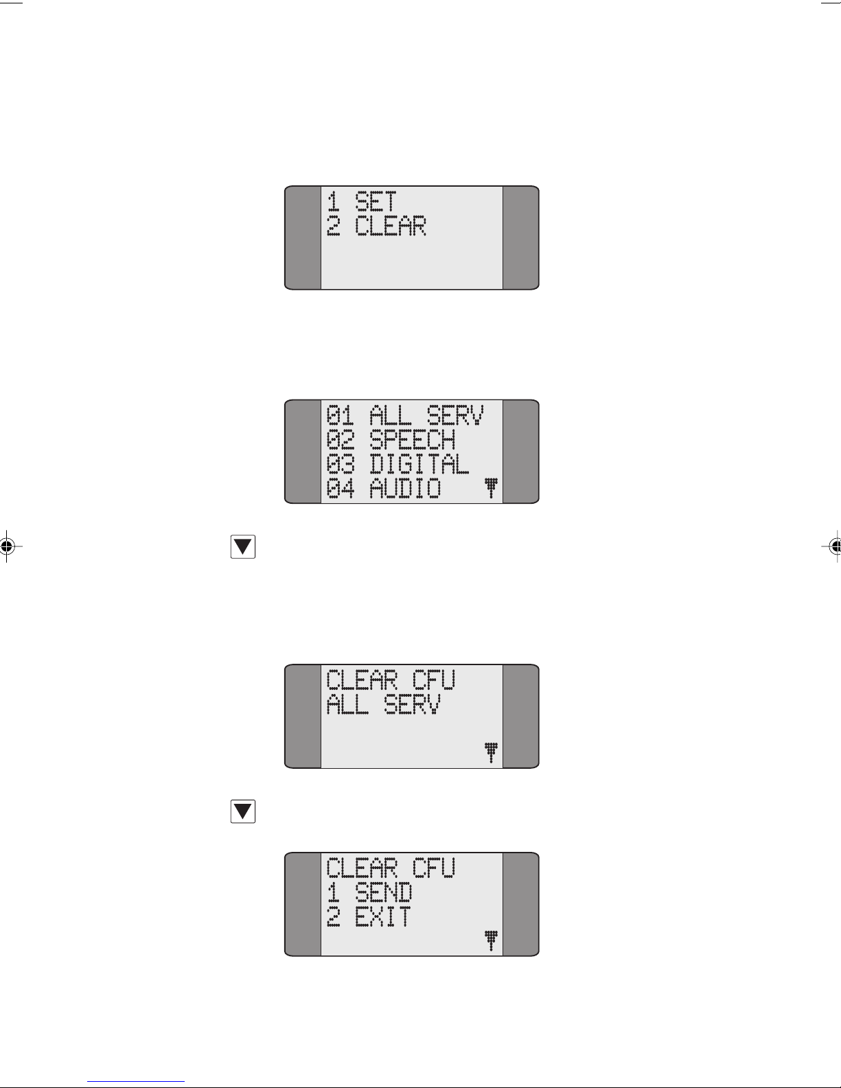
Trend AuroraPlus User Guide
Choose the type of Call Forwarding you wish to deactivate.
The following screen is displayed:
Choose CLEAR. Now select the service type for which you
wish to deactivate Call Forwarding.
Press the SCROLL key repeatedly to scroll through the
various service types. Enter a two digit service type code. If
you choose
ALL SERV Call Forwarding is deactivated on all
services. A screen similar to the following is displayed:
Press SCROLL to display the SEND/EXIT options:
4-24 429850
Page 93
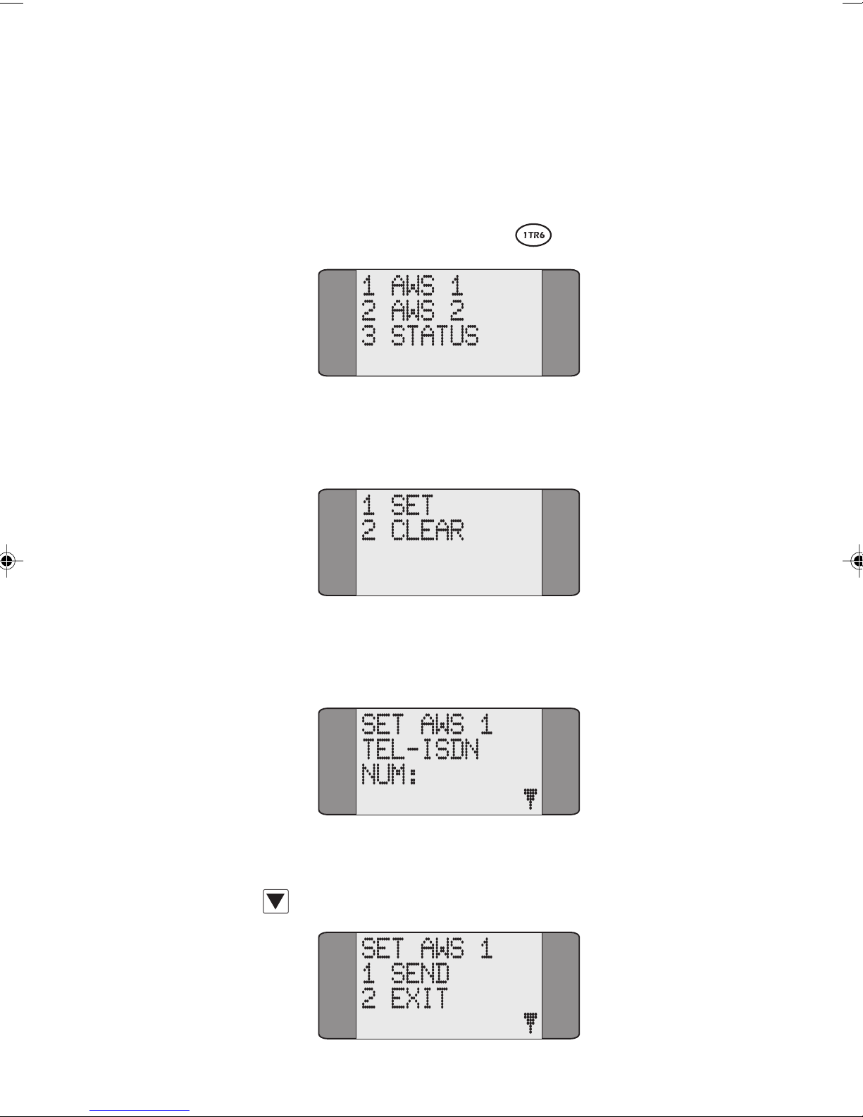
Call Establishment
Choose SEND to send the Deactivate Call Forwarding
request to the network.
WAIT is displayed while AuroraPlus
awaits an acknowledgement from the network. Alternatively,
choose
EXIT to return to the service type selection screens.
Activating Call Forwarding
Select the Call Forwarding type you wish to activate. The
following screen is displayed:
Choose SET to activate Call Forwarding. A screen similar to
the following is displayed:
Key in the number to which calls are to be forwarded to.
Press SCROLL to display the SEND/EXIT options:
Issue 5 - 04/01 4-25
Page 94
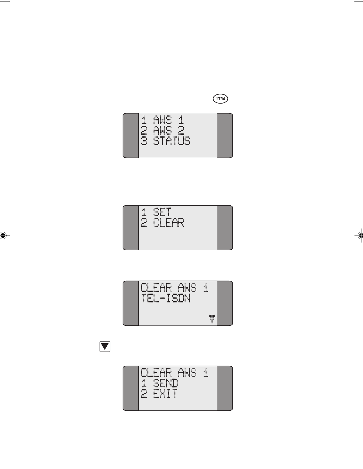
Trend AuroraPlus User Guide
Choose SEND to send the Call Forwarding Activation request
to the network.
acknowledgement. Alternatively, choose
previous
Set/Clear options.
WAIT is displayed while AuroraPlus awaits an
EXIT to return to the
Deactivating Call Forwarding
Choose the type of Call Forwarding you wish to deactivate.
The following screen is displayed:
Choose CLEAR. A screen similar to the following is displayed:
Press SCROLL to display the SEND/EXIT options:
4-26 429850
Page 95
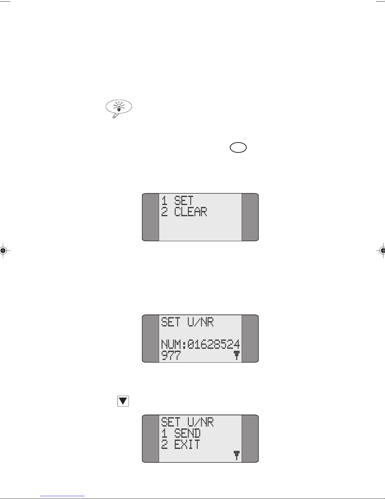
Call Establishment
VN
Choose SEND to send the Deactivate Call Forwarding
request to the network.
WAIT is displayed while AuroraPlus
awaits an acknowledgement from the network. Alternatively,
choose
EXIT to return to the previous Set/Clear options.
Tip
To display Call Forwarding settings on the line, refer to
Performing a Status Request in Chapter 5.
Activating Call Forwarding
When you select Call Forwarding, AuroraPlus displays the
following screen:
Choose SET to activate Call Forwarding—the type of call
forwarding depends on which service has been subscribed to.
A screen is displayed for you to enter the number to which
calls are to be forwarded.
Type the forwarded-to number.
Press SCROLL to display the SEND/EXIT options:
Issue 5 - 04/01 4-27
Page 96
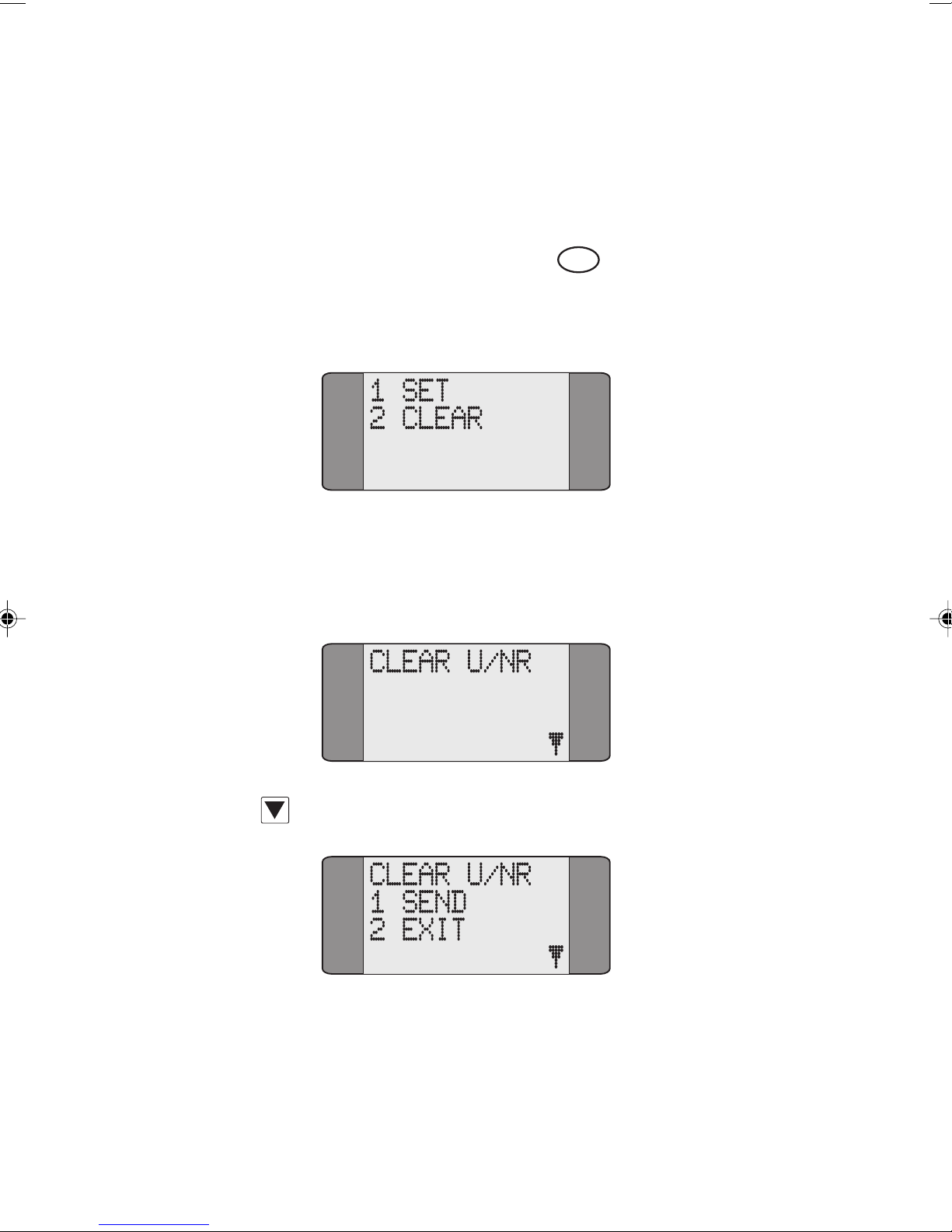
Trend AuroraPlus User Guide
Choose SEND to send the Call Forwarding request to the
network.
WAIT is displayed while AuroraPlus awaits an
acknowledgement from the network. Alternatively, choose
EXIT to return to the SET/CLEAR options.
Deactivating Call Forwarding
VN
When you select Call Forwarding, AuroraPlus displays the
following screen:
Choose CLEAR to deactivate Call Forwarding—the type of
call forwarding depends on which service has been
subscribed to. A screen similar to the following is displayed:
Press SCROLL to display the SEND/EXIT options:
Choose SEND to send the Deactivate Call Forwarding
request to the network.
awaits an acknowledgement from the network. Alternatively,
choose
4-28 429850
WAIT is displayed while AuroraPlus
EXIT to return to the SET/CLEAR options.
Page 97
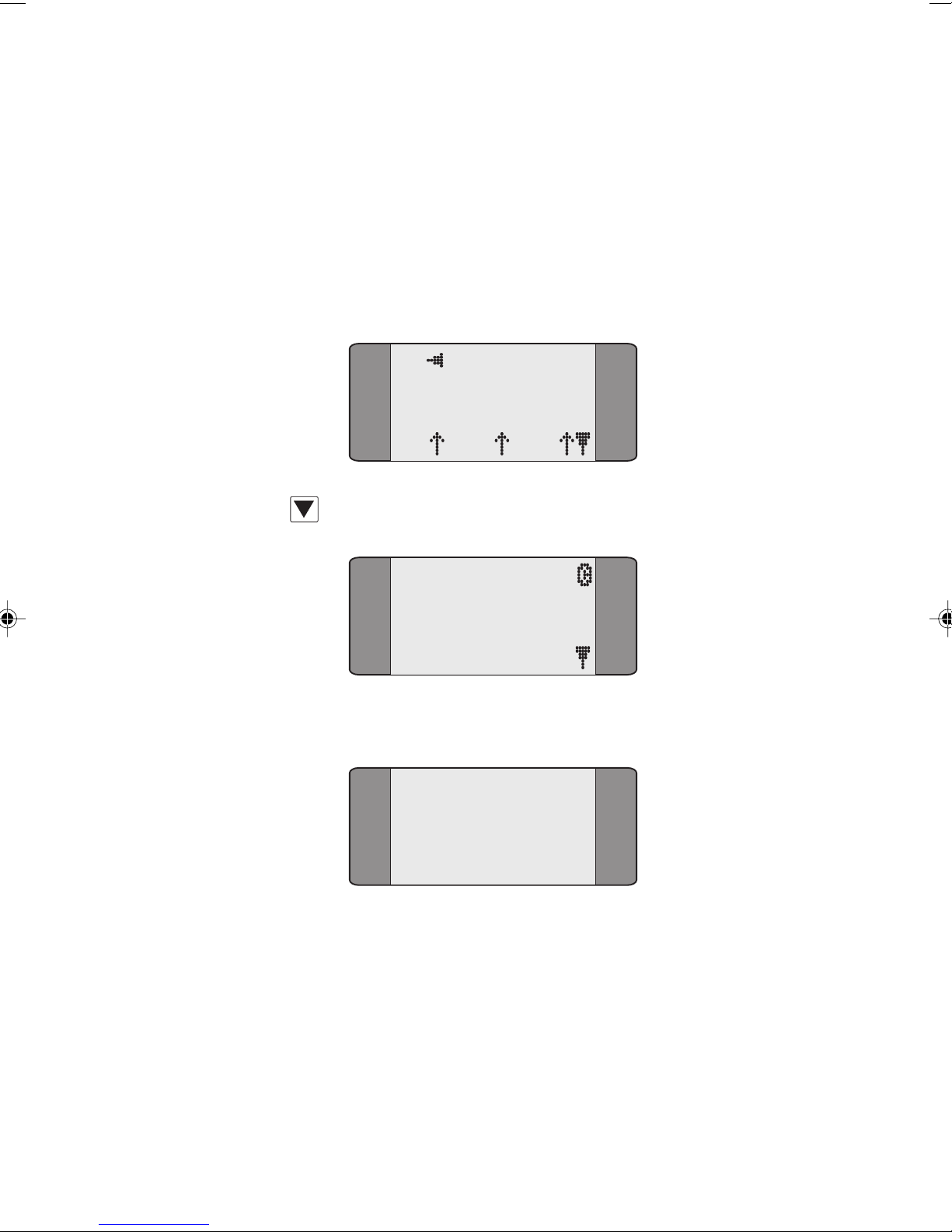
Call Deflection
Call Deflection enables a user receiving an incoming call to
send the call to another number. Call Deflection can only be
performed when a call is received, unlike Call Forwarding
that is set up in advance.
When an incoming call is presented:
Press SCROLL.
Call Establishment
B1 CALL
SPEECH
L1 L2 L3
SUPP SERVIC
1 CALL DEFL
2 UUS SRV 2
Choose CALL DEFL.
CALL DEFLECT
1 ADDRESS
2 INVOKE
To choose the number you want to transfer the call to,
choose ADDRESS, then enter the number (up to 19 digits).
Issue 5 - 04/01 4-29
Page 98
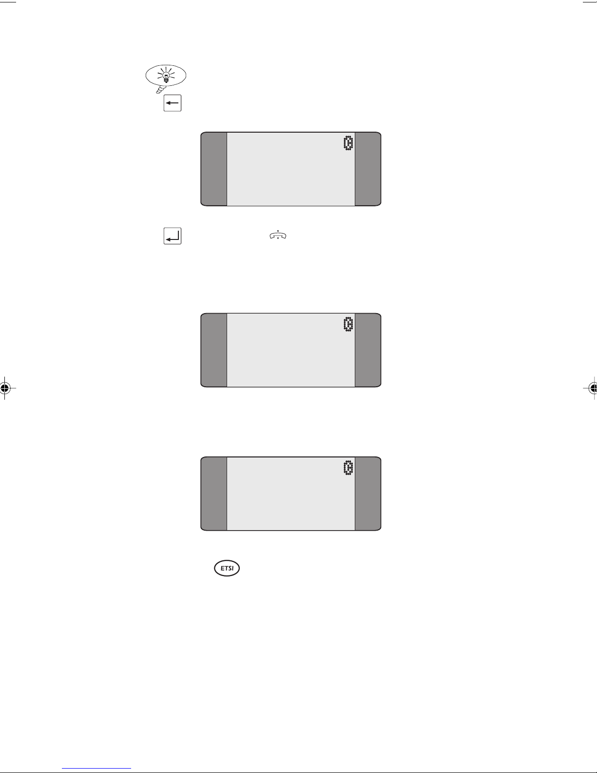
Trend AuroraPlus User Guide
Tip
To return to the previous screen, press CLEAR.
CALL DEFLEC
NUM:
Press ENTER ( ) to return to the previous screen.
To invoke Call Deflection, choose INVOKE, the following
screen is displayed.
CALL DEFLEC
If the Call Deflection is successful, the following screen is
displayed:
Keypad Facility
The Keypad facility enables you to send requests to the
network to initiate and test the operation of 'Stimulus'
controlled Supplementary Services. The Keypad facility can
RES:
INVOKED
CALL DEFLEC
RES:
AVAIL
be used either with or without an active, established call.
4-30 429850
Page 99
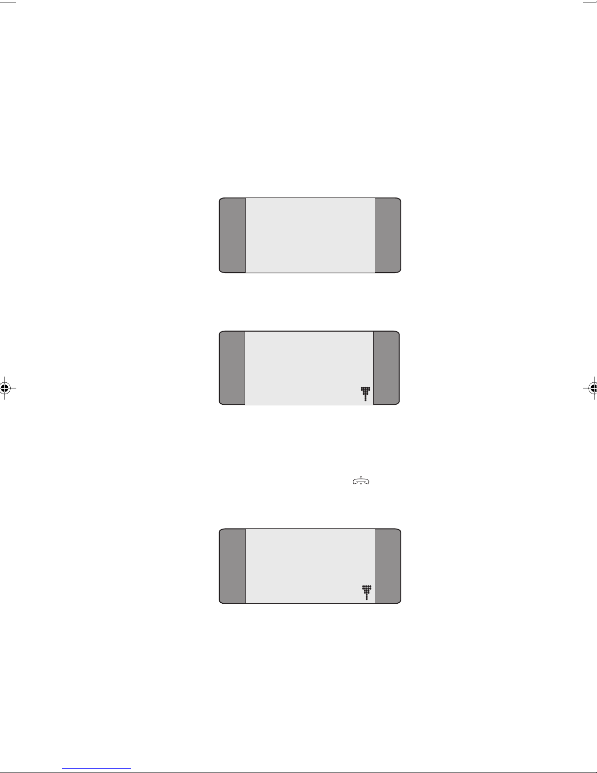
Call Establishment
Accessing the Keypad without an Active Call
Established
Choose CALLS from the Main Menu.
Choose SUPP SVCS to display the following Supplementary
Services screen.
1 CALL FWD
2 KEYPAD
3 RESUME
Choose KEYPAD.
B1 KEYPAD
1 EN-BLOC
2 OVERLAP
Choose the dialling mode you want to use.
If you choose EN-BLOC, the characters are sent in a block
when you press the ENTER ( ) key; if you choose
OVERLAP, the characters are sent as you press the keys.
B1 KEYPAD B
Issue 5 - 04/01 4-31
Notes on entering Keypad Codes
If the characters you enter start with # or *, and end with #,
they are sent in a keypad facility information element.
For example if you enter *21*6489#, it will be sent in a
keypad facility information element.
Page 100
Trend AuroraPlus User Guide
If you enter characters after the #, they are sent as a Called
Party Number information element.
For example if you enter *01*6489#90698, then *01*6489#
is sent in a keypad facility information element, and 90698 is
sent in the Called Party Number information element.
If the characters you enter start with a number, they will be
sent in a Called Party Number information element.
En-bloc dialling
When you are using en-bloc dialling you must enter the
characters before you can go off-hook.
Enter the Keypad code (refer to the appropriate Reference
Guide for your network's Supplementary Service codes).
The characters are displayed on the screen as you enter them:
B1 KEYPAD B
*346*#
Press the ENTER ( ) key.
The characters are sent.
B1 KEYPAD B
*346*#
To send another string, press CLEAR.
This returns you to the entry screen.
For information on how to send a Keypad code when a call
is active, see Accessing the Keypad during an Active Call.
4-32 429850
 Loading...