

Page 1
VSD2H Variable Speed Drives
A
D
ØF
ØG
IP21
S (ØH)
IP54
C (Ø25)
B
E
D
C
M (ØH)
B (ØI)
ØF
Data Sheet
VSD2H
Variable Speed Drives
Description
Variable motor speed drives suitable for HVAC applications
where the speed control of motors can be applied. They
convert xed frequency and voltage from the mains supply to
variable frequency and voltage enabling motors to be used with
maximum ef ciency resulting in signicant energy savings.
The control keypad can be mounted on the front of the unit or
can be remotely connected by way of a 2 m cable and mounted
on a panel or used as a handheld unit.
The keypad accesses the startup wizard which facilitates the
the application conguration for the user (pump/fan, PID loops,
multi-pump, cascade control).
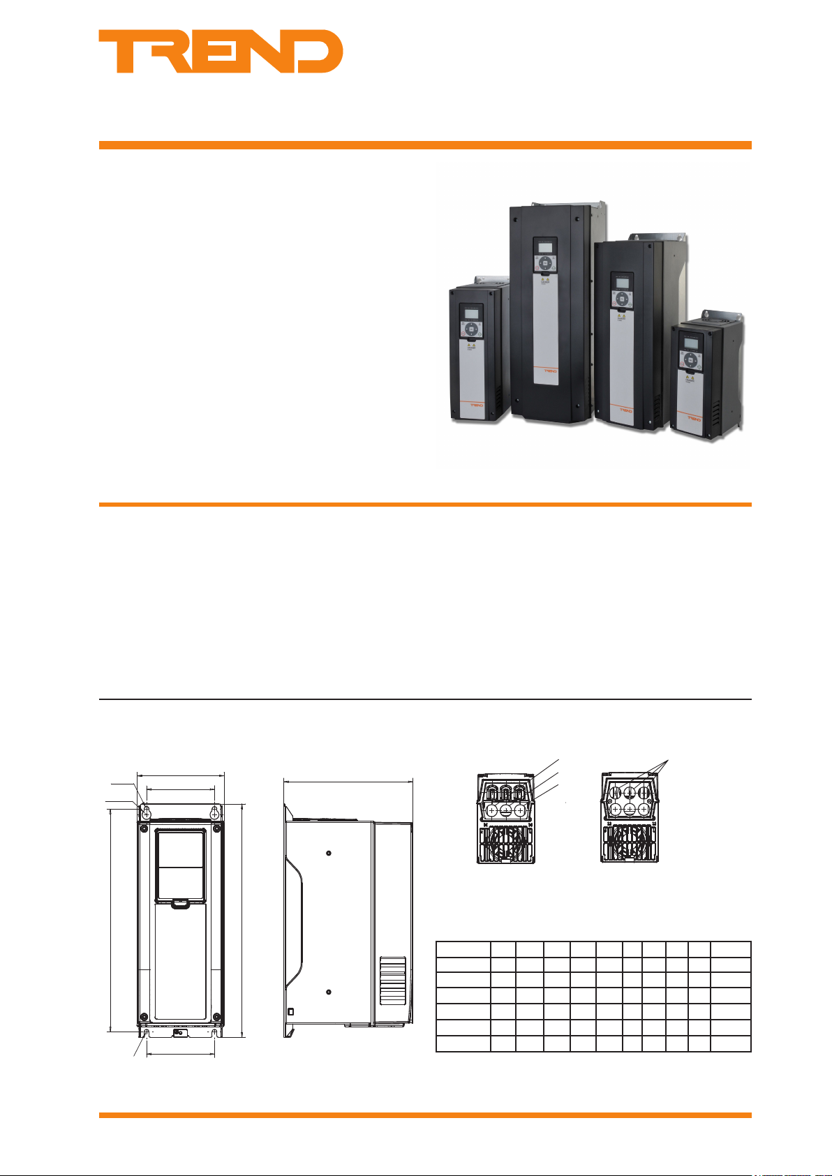
Physical (dimensions in mm)
3 A to 105 A units (unit size MR4 to MR7) - wall mounting
Features
▪ 380 to 480 Vac 3 phase
▪ current rating range from 3 A to 310 A
▪ IP21 and IP54 models available
▪ optional Trend system network interfaces (NXNI or NXIP)
▪ application congurable using wizard for a number pump or
fan scenarios
▪ real time clock tted with battery
▪ integrated RFI lter for typical building installation
▪ versatile PC tools available
▪ slim, space-saving, “bookshelf” design
▪ varnished printed circuit boards to maximise reliability
S= supply cable
M= motor cable
C= control cable
Current (A) A B C D E ØF ØG ØH ØI Frame
3 to 12 128 328 190 100 313 7 13 25 25 MR4
16 to 31 144 419 214 115 406 7 14 33 25 MR5
38 to 61 195 557 229 148 541 9 15.5 40 33 MR6
72 to 105 237 660 259 190 645 9 16 50 50 MR7
For 140 to 310 A sizes see next page
VSD2H Variable Speed Drives Data Sheet TA201104 Issue 3, 08-Oct-2013 1
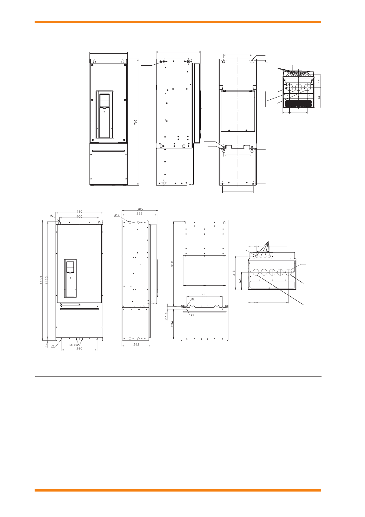
140 to 205 290 966 343 217 947 9 16 60 60 MR8*
261 to 310 480 1150 365 400 112 2 9 16 59 59 MR9*
* For MR8, MR9 detail see next page
Page 2
VSD2H Data Sheet
all Ø25
3x38
all Ø60
62,5 164
290
Ø22
343
Ø11
Ø9
216
672
694
956
235
217
Ø9
0
9
Motor
Supply
Control
Supply
Motor
Control
4 x 81.5 = 326
3 x 42 = 126
77
84
Ø25
Ø59
Physical (continued)
(dimensions in mm)
140 A to 205 A units
(unit size MR8)
wall mounting
IP21 and IP54
261 A and 310 A units (unit size MR9) wall mounting
IP21 and IP54
FUNCTIONALITY
The VSD2H range of variable speed drives provides 20 models (3 A to 310 A) for voltages from 380 to 480 Vac 3 phase with either
IP21 or IP54 rating. Designed for use in the HVAC environment, they enable fans and motors to regulate delivery of air and water in
variable ow applications. Where ow rates may be reduced, motor energy can be signicantly cut as the relationship between ow
rate and power follows a cube law hence reducing ow by 20% reduces power by 50%. The drives also enable saving in installation
costs; switchgear is eliminated, motor cables are reduced from 6 to 3 wires for larger drives, power factor correction capacitors are
not required, size and cost of cabling and fuses is minimised (as starting current is kept within nominal value).
The built-in application can be confgured to suit the user’s application using the star tup wizard; select either pump or fan, and
enter nominal motor information. There are additional mini-wizards for setting up multi-pump control and the PID controller, and
performing a resonance sweep.
2 VSD2H Variable Speed Drives Data Sheet TA201104 Issue 3, 08-Oct-2013
Page 3
Data Sheet VSD2H
Keypad
Control
U/T1
V/T2
W/T3
M
L1
L2
L3
Powe runit
....
control signals
Option
board
slot E
Option
board
slot D
Basic board A
Basic I/O board
Basic board B
Relay board
32 33
1 2 3 4 5 6 7 8 9 10 11
12 13 14 15 16 17 18 19 30 AB
21 22 23
24 25 26
Relay Board
Basic I/O Board
10 kohm
RS485 A (-)
RS485 B (+)
digital input
ground isolation
link
1
2
3
4
5
6
7
8
9
10
11
12
13
14
15
16
17
18
19
30
10 Vref
AI1+
AI1AI2+
AI224Vout
GND
DI1
DI2
DI3
COM
24Vout
GND
DI4
DI5
DI6
COM
AO1+
AO1+24 Vin
Reference
(voltage)
Reference
(current)
Basic I/O board
A
B
(current)
Main unit
Detachable
Keypad
Control
terminals
Power
terminals
Cover
Cable
protection
plate
HARDWARE
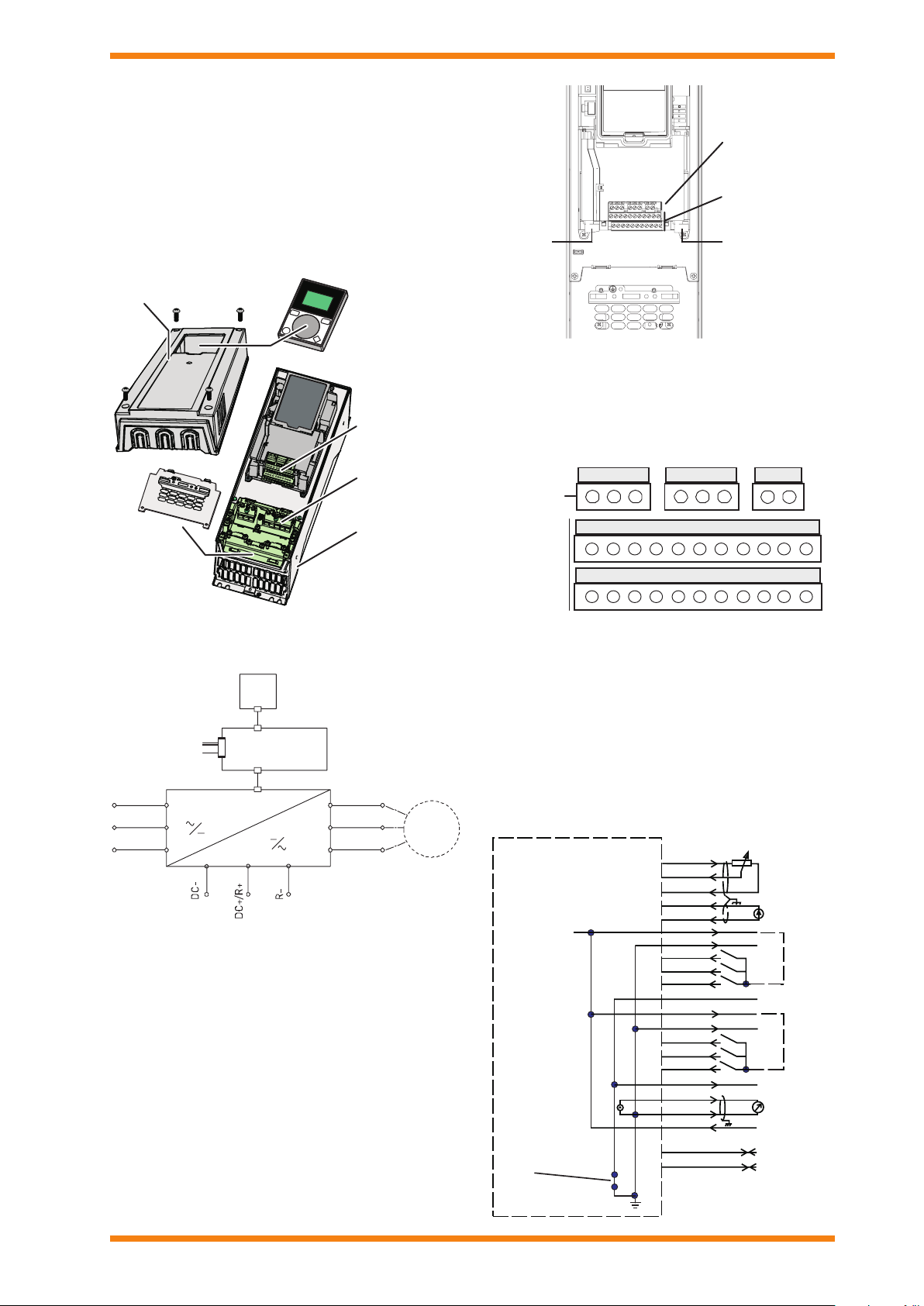
Unit: The unit is housed in a slim, space saving, bookshelf style
enclosure that should be mounted vertically on a wall or on the
back panel of a cubicle. Enough space should be left round
the unit for cooling. Most units have 4 point mounting with two
keyhole slots.
System: The drive consists of the main unit, the cover, and a
detachable keypad unit.
When the frequency converter is delivered from the factory,
the control unit includes the standard complement of two basic
boards, the Basic I/O Board in slot A, and the Relay Board in
slot B.
Additional boards can added to slots D and E. An NXIP or NXNI
Trend network interface can only be tted in slot D.
Main unit: The main unit consists of the power unit and the
control unit.
The power unit provides connections for the input mains supply
(L1, L2, L3) and the output supply to the motor (U, V, W).
The control unit is based around a microprocessor. The
microprocessor controls the motor based on the information it
receives through measurements, parameter settings, control I/O
and from the control keypad. The control unit of the frequency
converter consists of the control board and up to 4 additional
boards connected to the slot connectors (identied by letters A,
B, D, E) of the control board.
VSD2H Variable Speed Drives Data Sheet TA201104 Issue 3, 08-Oct-2013 3
The basic boards’ terminals are shown above.
The Basic I/O Board (tted as standard) has:
2 analogue input channels, separately switchable to
voltage (0(2) to 10V) or current (0(4) to 20 mA)
6 digital input channels (0 to 5 V =0, 15 to 30 V = 1)
1 analogue output channel, switchable to voltage (0 to
10V) or current (4 to 20 mA).
RS485 serial bus terminal pair (for BACnet MS/TP or
Mo dbus)
The defaults for the analogue inputs and output are indicated
in the diagram below; they may be changed using the DIP
switches (see below).
Page 4
VSD2H Data Sheet
+t
21
22
23
25
26
Relay board
RO1/1
RO1/2
RO1/3
RO2/2
RO2/3
2829TI1+
TI1-
21
RO2/1
from I/O board terminal 13
from I/O board terminal 12
Example: RUN light
Example: Motor temperature
trip thermistor
RUN
GND
24Vout
Terminal Signal Information Factory Setting
1 10 Vref +10 Vdc Reference voltage 10 mA max.
2 A I1+ Analogue input 1 voltage or current
3 A I1- Analogue input 1 common
4 AI2+ Analogue input voltage or current
5 AI2- Analogue input c2 ommon
6 24 Vout 24 V auxiliary voltage output ±10 %, 250 mA max.
7 GND I/O ground Ground for reference and controls
8 DI1 Digital input 1
9 DI2 Digital input 2 No function
10 DI3 Digital input 3 External fault
11 COM Digital input common
12 24 Vou t 24 V auxiliar y voltage output as terminal 6
13 GND I/O ground as terminal 7
14 DI4 Digital input 4
15 DI5 Digital input 5 Preset speed select B1
16 DI6 Digital input 6 Fault Reset
17 COM Digital input common as terminal 11
18 AO1+ Analogue signal (+output)
19 AO1- Analogue output common
30 +24 Vin 24 Vdc auxilar y input +24 Vdc, 100 mA , ±10% for backup power*
A RS485 A (+)
B RS485 A (-)
Fieldbus communication
DIP switch 4 selects V or mA .
Differential input if not connected to ground
DIP switch 3 selects V or mA .
Differential input if not connected to ground
Rin= 5 kohm min.
0 to 5 V =’0’
15 to 30 V =’1’
Common for DI1 to 6. Can be disconnected
from ground by removing link
Rin= 5 kohm min.
0 to 5 V =’0’
15 to 30 V =’1’
DIP switch 2 selects V (0 to 10V) or I (0 to
20 mA)
Differential receiver/transmitter;
Use for BACnet MS/TP, or MODBUS RTU
Speed Reference, 0 to !0 V
PID actual va lue 1, 4 to 20 mA
Start Forward
Preset speed select B0
Output frequency, 0 to 20 mA
*The control board can be powered externally by
connecting an external power source to terminal 30.
This voltage is sufcient for parameter setting and for
keeping the control unit active. Note however that the
measurements of the main circuit (e.g. DC-link voltage,
unit temperature) are not available when the mains is not
connected.
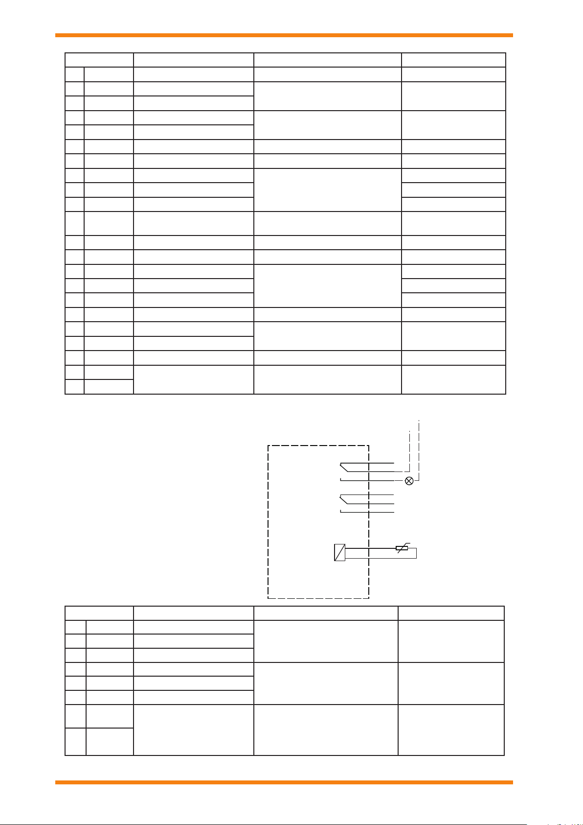
The Basic Relay Board (tted as standard) has:
2 changeover relay output channels
1 thermistor input channel
Terminal Signal Information Factory Setting
21 RO1/1 Relay output 1 No r m a l l y Cl osed
23 RO1/3 Relay output 1 Normally Open
24 RO2/1 Re l a y ou t p u t 2 Nor m a l l y Cl o s e d
26 RO2/1 Relay output 2 Normally Open
28 TI1+
29 TI1-
Thermistor input
Switching capacity: 24 Vdc/8 A
250 Vac/8A
125 Vdc/0.4 A
Min. switching load
Switching capacity: 24 Vdc/8 A
250 Vac/8A
125 Vdc/0.4 A
Min. switching load
R
= 4k7 ohms,
TRIP
Measuring voltage = 3.5 V
RUN (active)22 RO1/2 Relay output 1 Common
FAULT (active)25 RO2/1 Relay output 2 Common
Motor temperature
trip thermistor (PTC).
If thermsisor circuit
is not used it must
be short-circuited
4 VSD2H Variable Speed Drives Data Sheet TA201104 Issue 3, 08-Oct-2013
Page 5
Data Sheet VSD2H
RS48 5
AO1
AI2
AI1
OFFON
Current
RS485 fieldbus termination resistor
Current
Current
Voltage
Voltage
Voltage
Default positions areshown
DIPSwitches
Switch 1
Switch 2
Switch 3
Switch 4
OK
STOP START
BACK
RESET
LOC
REM
FWD REV I/O KEYPAD BUS
READY RUN STOPALARM FAULT
Indicators:
Status
Indicators:
Alarm, Fault
Indicators:
Direction
Indicators:
Controlplace
Groupor parametername
Menu location
OK
STOP START
BACK
RESET
LOC
REM
Main Men u
Quick Setup
(17)
Parameters
(12)
STOP READY I/O
ID:M1
(5)
Monitor
Location field
Status field
(ParameterID number
Main Men u
Quick Setup
(17)
Parameters
(12)
STOP READY I/O
ID:M1
(5)
Monitor
Activated group/item. Press OK to enter.
Number of itemsinthe group
STOP/RUN
Status field
READY/NOT READY/FAULT
Control place:
PC/IO/KEYPAD/FIELDBUS
ALARM
and current menu location)
Number of itemsinthe group
Direction
Trend Network Interfaces: An optional system network interface can be tted into the VSD2H drive. It is plugged into slot D, and
enables the unit to be monitored and controlled from Trend supervisors (using Text comms), and from Trend IQ controllers (using IC
comms). There are the IQ system current loop Lan interface, NXNI (which provides a standard four wide current loop Lan terminal
set), and the Ethernet interface, NXIP. See NXNI data sheet TA200544 or NXIP data sheet TA200826 for details. Note that the NXNI
allows the unit to be monitored by all Trend IQ controllers, but it can only be written to by IQ3, IQ4. or IQeco controllers.
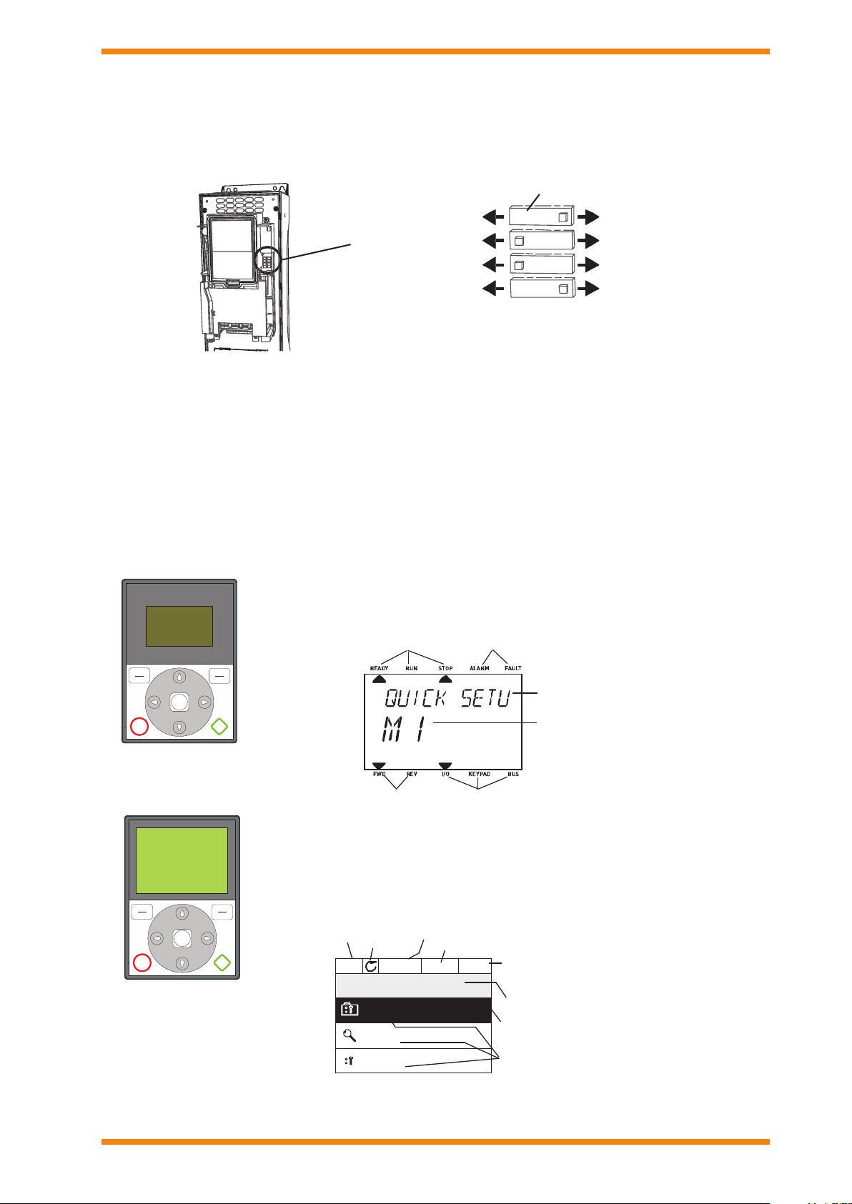
DIP Switch
The 4 DIP switches have 3 functional positions, left, middle, and right. The middle position is used for test mode. The switches are
used to set the folowing parameters:
Switch 1: RS485 eldbus Terminator resistor, on or off (default off)
Switch 2: Analogue Output 1, current or voltage (default current)
Switch 3: Analogue Input 2, current or voltage (default current)
Switch 4: Analogue Input 1, current or voltage (default voltage)
Control Keypad: The control keypad can be used for setting the frequency converter’s parameters, reading status data, and giving
control commands. It is detachable and can be operated externally being connected via a cable to the main unit. There are two
accessory kits available:
ACC/VSD2H/HAND HELD KIT: This enables the keypad to be detached from the unit and to be used as a hand held unit
connected to the VSD by a 2 m cable.
ACC/VSD2H/DOOR MOUNTING KIT: This enables the keypad to be detached from the unit and to be mounted in the panel
door connected to the VSD by a 2 m cable.
The standard text keypad features an alphanumeric display with seven indicators for run status
(READY, RUN, STOP, ALARM, FAULT, FWD, REV), and three indicators for control source (I/O,
KEYPAD, BUS). There are also two text lines displaying description (of menu, value or fault) and
location (reference to menu and parameter) or value (numerical, textual values).
text keypad
A replacement advanced commissioning keypad is available as an accessory (ACC/ VSD2H
GRAPHIC DISPLAY). The commissioning keypad can also be used to store the parameter settings
and transport them to another drive (ref: M6.5). The top row is the drive status eld, and the second
row is the location eld describing the position in the selection menu. The remaing three rows
can be used for display of information. The commissioning keypad has extra features (help and
information displays, favourites, multi-monitor of 9 selected values).
commissioning keypad
(ACC/VSD2H GRAPHIC
DISPLAY accessory)
VSD2H Variable Speed Drives Data Sheet TA201104 Issue 3, 08-Oct-2013 5
Page 6
VSD2H Data Sheet
Scrollme nu up
Increase valu e
Scrollme nu down
Decrease valu e
Move cursorleft
Move backward in me nu
Exit edit mo de
Resetfaultswithlon gpre ss
Change cont rolpla ce
Stop butt on
Enteractiv elevel /ite m
Confirmselecti on
OK
Startbutton
Move cursorright
max. 40 mm
Ethern et
cable
B
20 A
11
89
10
12
B
131415 161718 19
20 A
1
11
234 567
8910
21 2223 242526
2829
RS485
terminals
(A andB)
HARDWARE (continued)
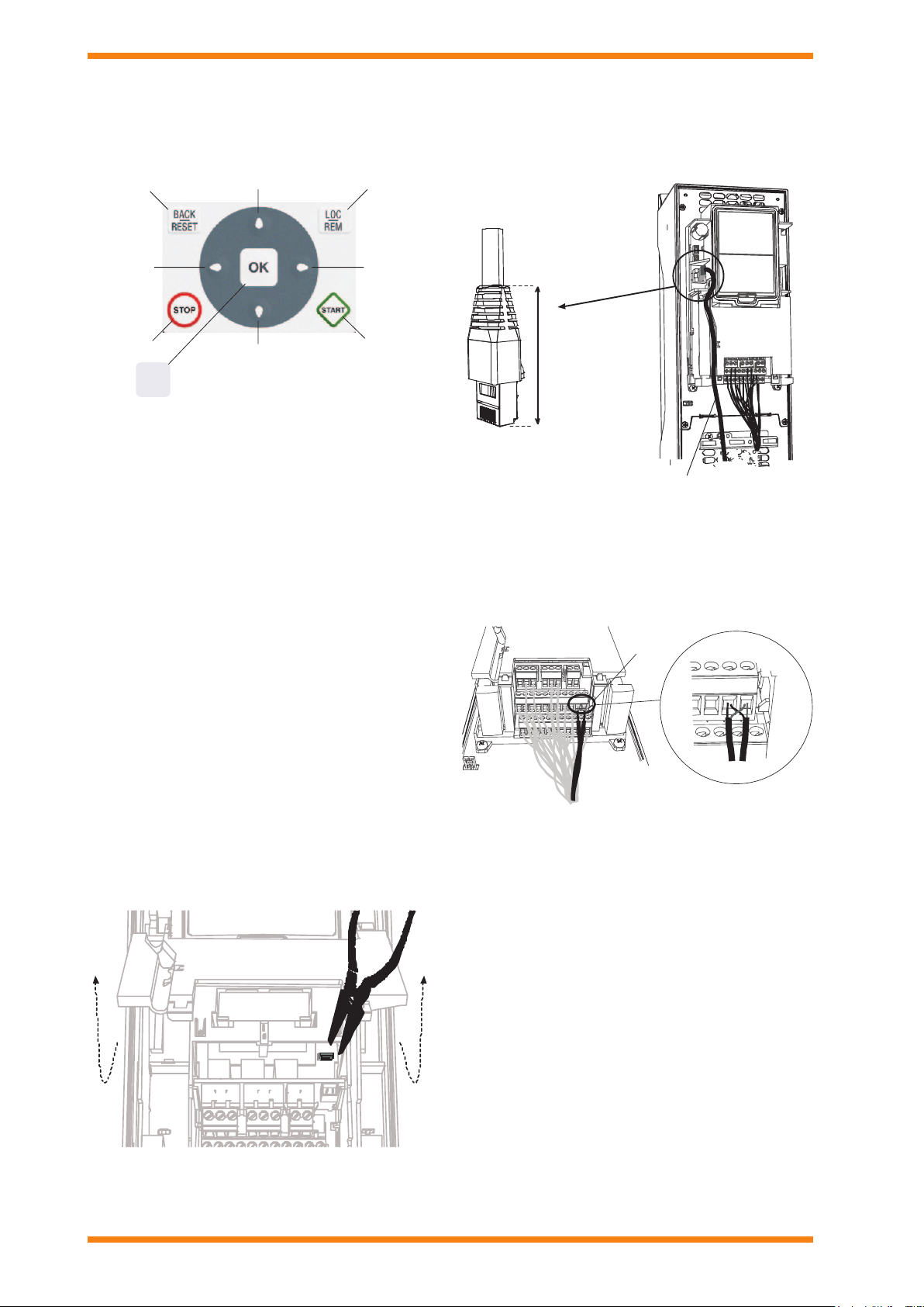
The keypad has nine buttons which are used for controlling the
drive, setting parameters, and monitoring values. The buttons
are the same for both types of keypad.
The keypad is the control source by default (i.e. Local) but it
can be changed to Remote at any time by pressing the LOC/
REM but to n. (The control so urce has to be changed to Remote/
Fieldbus for the NXNI or NXIP to control the drive.)
The main menu consists of 7 individual items which are browsed
using up and down buttons, the submenus under these menus
are then browsed by selecting OK.
Quick setup: A group of the parameters most commonly used
during installation and commisioning
Monitoring: This enables parameters to be monitored only.
Parameters: This enables the parameters to be edited.
First the group of parameters is selected, then the individual
parameter. The actual meanings of the parameters vary with
the conguration being used.
Diagnostics: This enables current and historical faults to
be viewed, faults to be reset , and counters and software
information to be viewed.
I/O and hardware: This selects Basic I/O, any additional boards
in slots D or E (an NXNI or NXIP in slot D would be shown as
OPTCO), Real time clock, the drive fan, keypad settings and
eldbus (RS485 or Ethernet) parameters.
User settings: Language, application, parameter backup and
restore to and from keypad.
Favourites: (advanced commissioning keypad only) This
enables the user to collect a set of parameters from any of the
keypad menus.
Ethernet Connection: The Ethernet connection for BACnet
over IP or MODBUS TCP is situated under the cover to the left
of the control keypad, and the cable is run in a channel cut in the
plastic ap. A shielded RJ45 connector should be used.
RS485 Connection: The RS485 connection for BACnet over
MS/TP or MODBUS RTU uses terminals A and B (A negative,
B positive) in the basic I/O board terminal set. STP (Shielded
Twisted Pair), type Belden cable 9841 or similar should be used.
The terminator (see above DIP Sw 1) should only be switched
on if the unit is at one end of the bus.
Digital Input Isolation: The digital inputs (DI1 to DI6) can be
isolated from ground by removing a link on the control board
as shown.
6 VSD2H Variable Speed Drives Data Sheet TA201104 Issue 3, 08-Oct-2013
Real Time Clock: The VSD2H has a real time clock with timer
functions. The unit comes complete with a Real Time Clock
battery installed to maintain the time during power failure..
Integrated RFI-lter: The units have integrate RFI lters,
enabling them to comply with EN61800-3 category C2 (suitable
for public electricity net works such as buildings).
Integrated DC choke: The units are equipped with DC chokes
to reduce harmoncs (THD), enabling them to comply with
EN61000-3-12.
Integrated stress removal: Stress removal and 360°
grounding of power cables inside the unit with clamps. No need
for extra glands.
Page 7

Data Sheet VSD2H
FIRMWARE
Full details of the rmware are diven in the VSD2H Application
Manual TE201103.
Quick Setup
On initial power up, the Startup Wizard will prompt for:
Language
Daylight saving (Russia/US/EU/off)
Time, Day, Year
Run Startup Wizard (Y/N)
If yes:
Process (pump or fan)
Motor Nominal Speed (range 24 to 19200 rpm)
Motor Nominal Current (range depends on unit)
There are other mini-wizards that can be used for setting the
following:
PID: Three term control for motor or external device by
way of I/O.
Pump and Fan Cascade: Cascade control of several
pumps or fans.
Resonance Sweep: For elimination of possible
resonance points in the system.
The Quick Setup menu, mentioned above, enables access to
the parameters most commonly used during installation and
commissioning including access to the Startup, PID, and Pump
and Fan Cascade wizards
Uninterruptible Operation and Energy Saving
High Switching Frequency: The VSD2H is capable of
providing the maximum power with high switching frequency.
Benet: Low audible noise from the motor.
Prohibit frequency: Overriding the critical frequencies to
avoid resonance. Can be set with the help of resonance sweep
wizard. Benet: Elimination of resonance.
Maintenance counters/alarms: The drive can be programmed
to notify on upcoming maintenance for the system or the drive
itself. Benet: Reliability
Temperature-controlled fans: Fan stops operating when
not needed Benets: Less audible noise from the VSD itself.
Energy savings.
Advanced HVAC Control
Time based control: With the help of the real time clock and
calendar functionality the drive can be programmed to perform
functions based on time. Benets: Cost savings. Flexibility.
Inbuilt PID controller: Normal and Inverse Regulation, Delta P
regulation with 2 standard pressure transmitters, Feed for ward
control, Less wiring since sensor normally close to inverter.
Benet: Cost saving. Faster response to process closed loop.
Sleep Mode: Shutting down the motor, when no demand.
Benet: Energy savings.
Pressure loss compensation: For compensating e.g. wrongly
placed sensor in the system. Benet: Time and cost saving.
Over temperature ride-through: Automatically adjusts
switching frequency and/or speed of the motor to adapt to
unusual increase in ambient. Benet: Uninterruptible operation.
Over temperatureride-through: Automatically adjusts
switching frequency and/or speed of the motor to adapt to
unusual increase in ambient. Benet: Uninterruptible operation.
RTO –Ramp Time Optimizer When problematic areas are
identied in acceleration or deceleration the drive automatically
expands the times needed for this to avoid mechanical stress
to the system. Benet: Decreased mechanical stress to the
system.
Trip free output switching Ensures trip free operation
when an output switch (e.g. safety switch) is operated between
the motor and the VSD. Truly intelligent and highly reliable
function to ensure better functionality than with any other VSD.
Benet: Uninterruptible operation.
Energy Saving function “Flux Optimization”: Flux
Optimization automatically minimizes energy consumption.
Benet: Even 5% increase in energy savings.
Congurable Auto reset function: Auto restar t function can
be congured to make VSD restart automatically once fault is
addressed. Benet: Uninterruptible operation.
VFD and Motor Control
Single input control: Analog signal rising edge can be used to
start the device without additional start signal to a digital input.
Benet: Cost and time savings.
Flying start: Ability to get an already spinning fan under speed
control. Benets: Improved performance·. Very important in
clean room production.
Pump Soft ll: Feature to prevent the overpressures when
lling empty pipe work. Benet: Longer lifetime of the system.
Fire override mode: Keeps fan/pump running in case of re.
Benet: Legal requirement.
Pump and Fan Cascade control with full auto-change:
Controls total pumping system with several parallel pumps by
equally sharing the load. Also the master pump can be included
in auto-change loop. Benets: Longer lifetime of the system.·
Cost savings.
SOFTWARE
Windows based PC utility tools are available for making the use
of the Trend VSD2H as easy and convenient as possible. The
tools facilitate installation, commissioning, and maintenance.
The software is self-documenting from its integral help le. The
minimum requirement for using the software is a PC and a USB
to RS485 interface cable (e.g. ACC/VSD2H/USB-PC/CABLE,
3 m), to be connected to the RS485 terminal behind the control
panel. The software tools are available as a download from
Partnernet.
Drive Care PC Tool: The Drive Care tool is easy-to-use
commissioning software for the control of the VSD2H. It enables
the following:
Setting up parameters with the PC
Saving Settings to the PC
Creating commissioning documentation
Comparing paramters settings
Monitoring view with graphics
Diagnostics
Controlling the drive from the PC
This tool also includes the Loader tool which enables the
downloading of rmware or applications.
Automatic torque boost function: Boosts initial voltage to
start high inertia fans. Benet: Avoids tripping and enables
smooth starts also to high inertia loads.
VSD2H Variable Speed Drives Data Sheet TA201104 Issue 3, 08-Oct-2013 7
Note that the drive conguration can be loaded from one drive
into the advanced commissioning keypad (ACC/VSD2H/
GRAPHIC DISPLAY), and downloaded into another drive.
Page 8
VSD2H Data Sheet
INSTALLATION
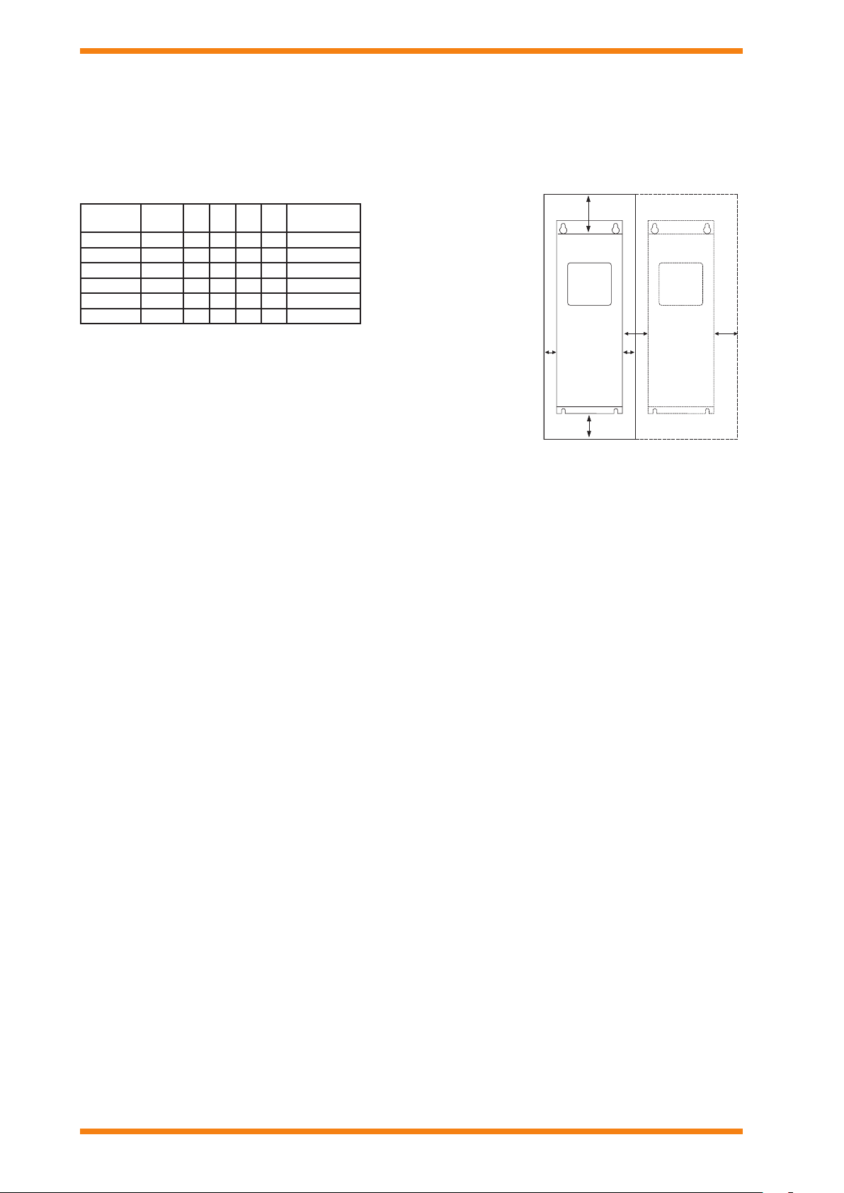
CLEARANCES
The Trend VSD2H drive must be installed in a ver tical position. It can be mounted on a wall or in an enclosure using four screws or
bolts. The cooling airow to the drive must not be blocked in any way, recirculation of air inside the enclosure should be avoided.
Different acts of maintenance also require certain amount of free space.
Make sure that the temperature of the cooling air does not exceed the maximum ambient temperature of the converter.
Current (A) Frame *A *B C D
3 to 12 MR4 20 20 10 0 50 45
16 to 31 MR5 20 20 12 0 60 75
38 to 61 MR6 20 20 160 80 190
72 to 105 MR7 20 20 250 100 185
140 to 205 MR8 20 20 300 150 335
261 to 310 MR9 20 20 350 200 621
Cooling Air
Required m
* Minimum clearances A and B
3
/h
for drives with IP54 enclosure
is 0 mm
Key:
A: clearance around the freq. converter (see also B)
B: distance between two drives or distance to cabinet wall
C: free space above drive
D: free space below drive
If several units are mounted above each other the required space between them equals C+D. Also the outlet air used for cooling the
lower unit must be directed away from the inlet air to be used by the upper unit.
INSTALLATION PROCEDURE
Overload protection of the supply cable should be considered (e.g. fuses). The use of shielded motor cables is recommended; they
should be routed as far away from other cables as possible, and cross other cables at right angles. The motor cable shield should
be grounded at both the VSD2H drive and at the motor.
The installation involves:
mount the controller in position
connect mains cable
connect motor cable
check mains and motor cable insulation
connect control cable
check quality and quantity of cooling air
check inside of drive for condensation
set up DIP switches
check all start /stop switches connected to I/O are at stop
switch on power to drive
congure the drive (e.g. using the keypad)
perform run test without motor
commission with motor connected
This installation procedure, is covered by the Trend VSD2H Installation Manual, TE201102.
MODBUS installation is covered by the MODBUS Protocol Installation and User’s Manual TE201235
BACnet installation is covered by the BACnet Protocol Installation and User’s Manual TE201234
8 VSD2H Variable Speed Drives Data Sheet TA201104 Issue 3, 08-Oct-2013
Page 9
Data Sheet VSD2H
L1 L2 L3
DC-
V
W
U
L1 L2 L3
M
3~
R-
R+
2
3
8
6
23
22
26
25
AI1+
AI1-
DI1
RO1/2 COM
RO1/3 NO
RO2/2 COM
RO2/3 NO
+24 V
AO SIG
AO 0 V
DO NO
DO COM
DI SIG
n
DI COM
n
DI SIG
n+1
DI COM
n+1
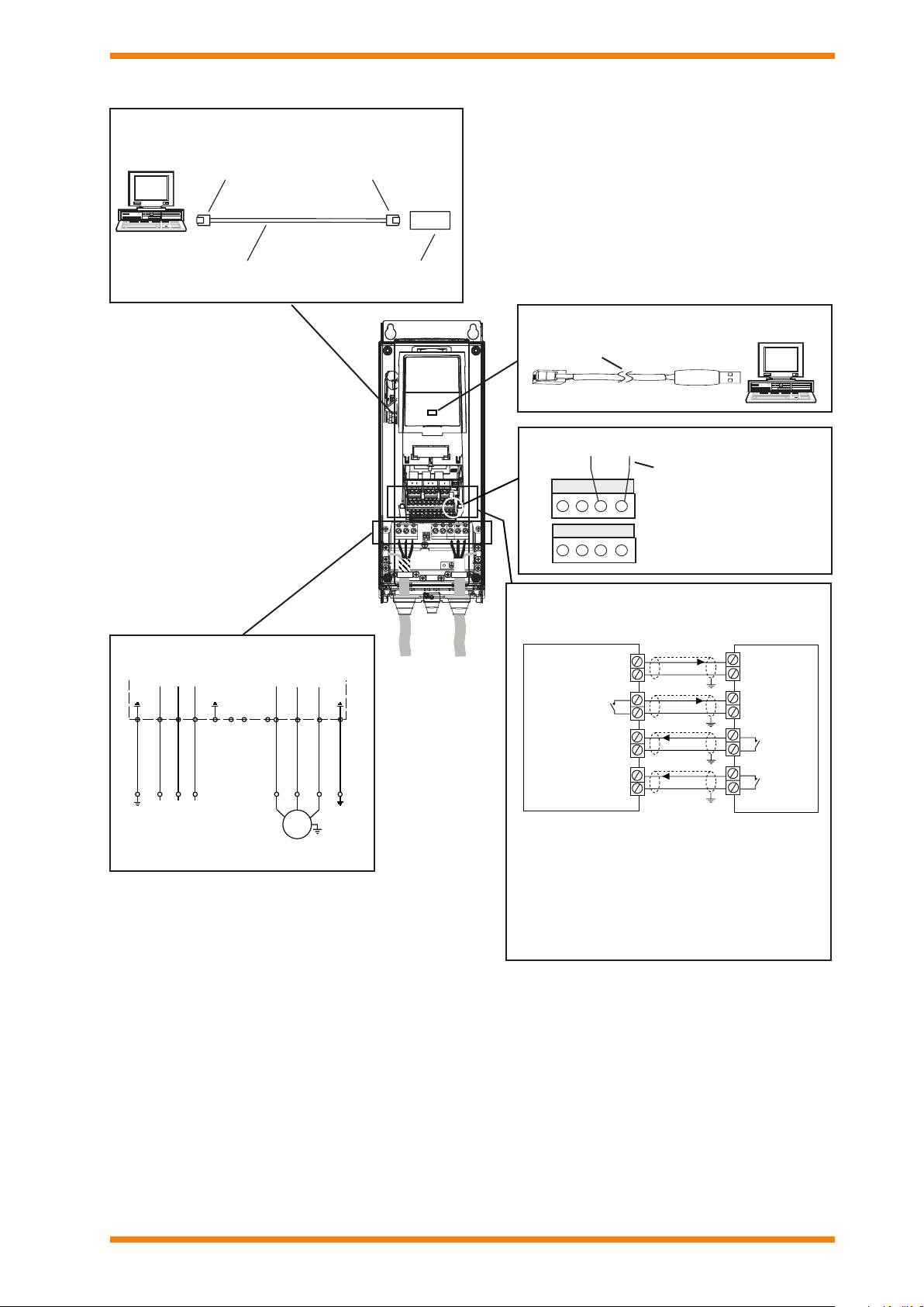
CONNECTIONS
Ethernet
(BACnet over IP or MODBUS TCP)
Connect to hub, or use crossover adaptor
RJ45RJ45
Standard Ethernet cable
Power Connections
3 phase mains supply
motor connection
XCITE/XA
crossover adaptor
USB
(connection to PC)
ACC/VSD2H/USB-PC/CABLE
RJ45
USB
RS485 (BACnet over MS/TP or MODBUS RTU)
Ensure correct polarity
+
-
19 30 AB
8 9 10 11
Use STP (Shielded Twisted
Pair), type Belden cable
9841 or similar.
Control Connections
Connect according to conguration
e.g connections to IQ Controller with default settings
Analo gue Output
0 to 10V
Digital
Output
Digital
Input
Digital
Input
IQ Controller
Volt age
Start forward
Running
Fault
VSD2H Drive
Note that the NXNI interface connects the drive
directly to the an IQ system current loop Lan, and
the NXIP connects the drive to an IQ system Lan on
Ethernet. They both enable the drive to be monitored
and controlled by IQs (IC comms) and Supervisors
(Text comms) - see order codes for details. Note that
the NXNI allows the unit to be monitored by all Trend
IQ controllers, but it can only be written to by IQ3,
IQ4, or IQeco controllers.
VSD2H Variable Speed Drives Data Sheet TA201104 Issue 3, 08-Oct-2013 9
Page 10
VSD2H Data Sheet
N
DISPOSAL
WEEE Directive:
At the end of their useful life the packaging,
product, and battery (if tted) should be disposed
Do not dispose of with normal household waste.
Do not burn.
of by a suitable recycling centre.
ORDER CODES
VSD2H/3P-480/[current]B/[IP]
e.g. VSD2H/3P-480/016B/IP21 :Variable speed drive for 16 A maximum load current with
local keypad unit and IP21 protection. Basic Relay Board
board tted as standard.
[IP] is either IP21 or IP54
ACC/VSD2H/GRAPHIC DISPLAY :VSD2H replacement advanced commissioning keypad
ACC/VSD2H/TEXT DISPLAY :VSD2H replacement text keypad
NXNI :NX variable speed drive IQ system current loop Lan inter face
(see NXNI data sheet)
NXIP :NX variable speed drive IQ system Lan on Ethernet interface
(see NXIP data sheet)
ACC/VSD2H/DOOR MOUNTING KIT :Kit to mount keypad unit on door; includes 2 m cable
ACC/VSD2H/HAND HELD KIT :Kit to produce hand held keypad unit; includes 2 m cable
ACC/VSD2H/USB-PC/CABLE :VSD2H to PC (USB por t) 3 m cable (to connect to PC
running VSD2H software tools)
XCITE /XA /5 :Pack of 5 Ethernet connecter adaptors for direct connection
of a PC to the VSD2H using a standard Ethernet cable
Additionally software tools are available from Partnernet:
Drive Care Tool: Commissioning software tool which includes the Loader Tool fo r updat ing drive r mwa re
and applications.
[current] nominal I
003 3 A
004 4 A
005 5 A
008 7 A
009 9 A
012 12 A
016 16 A
023 22 A
031 31 A
038 38 A
046 45 A
061 61 A
072 72 A
087 87 A
105 105 A
140 140 A
170 170 A
205 205 A
261 2 61 A
310 310 A
10 VSD2H Variable Speed Drives Data Sheet TA201104 Issue 3, 08-Oct-2013
Page 11
Data Sheet VSD2H
SPECIFICATIONS
Electrical
Supply voltage :380 to 480 Vac ±10% 3 phase,
Frequency :50 to 60 Hz -5, +10%
Connection to mains :once per minute or less
Starting delay :4 s (MR4 to MR6),
6 s (MR7 to MR9)
Motor voltage :0 to supply voltage
Motor current
Rated continuous : I
Low overload : I
Starting Current :I
, 3 A to 310 A dependent on option
L
(see table below)
+ 10%, for 1 minute every 10
L
minutes, with maximum 40 °C ambient
temperature (see table below).
, 2 x IL (maximum current required for
S
2 secs every 20 secs).
Rated
Order Code
Continuous
Current I
VSD2H/3P-480/003.. 3.4 3.7 1.1 6
VSD2H/3P-480/004.. 4.8 5.3 1.5 6
(A)
Output frequency :0 to 320 Hz
Frequency resolution :0.01 Hz
Control method :Frequency control, Open loop
sensorless vector control
Switching frequency :1.5 to 10 kHz
Defaults:
MR4 to 6: 6 kHz (except 0012, 0031,
0064, 4 kHZ)
MR7: 4 kHZ
MR8-9: 3 kHZ
Automatic switching frequency derated
in case of overload
Frequency reference
Analogue input :Resolution 0.1% (10 bit), accuracy ±1%
Keypad reference :Resolution 0.01 Hz
Field weakening point :8 to 320 Hz
Acceleration time :0.1 to 3000 secs
Deceleration time :0.1 to 3000 secs
Braking torque
L
DC brake :30% T
Low (10%)
overload
current
(A)
Nominal
Motor Shaft
Power P(kW)
at 40 °C
(nominal torque) without brake
N
resistor
Weight
(kg)
VSD2H/3P-480/005.. 5.6 6.2 2.2 6
VSD2H/3P-480/008.. 8 8.8 3 6
VSD2H/3P-480/009.. 9.6 10.6 4 6
VSD2H/3P-480/012.. 12 13.2 5.5 6
VSD2H/3P-480/016.. 16 17.6 7.5 10
VSD2H/3P-480/023.. 23 25.3 11 10
VSD2H/3P-480/031.. 31 3 4.1 15 10
VSD2H/3P-480/038.. 38 41.8 18.5 20
VSD2H/3P-480/046.. 46 50.6 22 20
VSD2H/3P-480/061.. 61 67.1 30 20
VSD2H/3P-480/072.. 72 79.2 37 3 7. 5
VSD2H/3P-480/087.. 87 95.7 45 3 7. 5
VSD2H/3P-480/105.. 105 115.5 55 37.5
VSD2H/3P-480/140.. 140 154 75 66
VSD2H/3P-480/170.. 170 187 90 66
VSD2H/3P-480/205.. 205 225.5 11 0 66
VSD2H/3P-480/261.. 261 28 7.1 132 10 8
VSD2H/3P-480/310.. 310 341 160 108
VSD2H Variable Speed Drives Data Sheet TA201104 Issue 3, 08-Oct-2013 11
Page 12

VSD2H Data Sheet
SPECIFICATIONS (continued)
Protective Functions
Overcurrent :Trip limit 4.0 x I
Overvoltage trip limit :911 V
instantaneously
L
Undervoltage trip limit :351 V
Earth fault protection :Protects drive from earth fault in motor
or cable
Mains supervision :Trips if any input phase is missing
Motor phase supervisor: Trips if any output phase is missing
Other :Unit overtemperature protection, motor
overload protection, stall protection,
motor underload protection, short
circuit protection of +24 V and +10 V
reference voltages
Inputs and Outputs
Analogue inputs :2 inputs (AI1, AI2) can be set to either
voltage or current by DIP switches.
Resolution 0.1 %, accuracy ±1 %
Voltage :0 (2) to +10 V, R
Current :0 (4) to 20 mA, R
The lower range (0 or 2 for voltage, 0
= 200 kohm,
in
= 250 ohm
in
or 4 for current) set by conguration
parameters M3.5.2.3 for AI1, M3.5.2.9
for AI2.
Digital inputs :6 inputs (DI1 to DI6) with positive or
negative logic, 0 to 5 Vdc =0, 15 to 30
Vdc=1
Motor thermistor input :(TI1) R
measuring voltage of 3.5 V
=4k7ohm (PTC) with
TRIP
Analogue output :1 output (AO1) can be set to either
voltage or current by DIP switch. R
<500 ohm, resolution 0.1 %, accuracy
±2 %. Short circuit protected.
Voltage 0(2) to 10 V
Current 0(4) to 20 mA,
The lower range (0 or 2 for voltage, 0
or 4 for current) set by conguration
parameter M3.5.4.1.3.
Relay outputs :2 outputs (RO1, RO2) isolated
changeover relay contacts. Switching
capacity 24 Vdc/8 A, 250 Vac/8 A, 125
Vdc/0.4 A. Minimum switching load 5 V/
10 mA .
Auxiliar y voltage out :+24 Vdc ±10 %, 250 mA max. Short
circuit protected. Available from t wo
terminals.
Auxiliar y voltage in :+24 Vdc ±10 %, 100 mA max. Backup
power enables parameter setting and
keeps control unit active during mains
failure.
10 V reference voltage out :(e.g. for potentiometer) +10
Vdc, +3% 10 mA max.
Environmental
Operating temperature :-10 °C (no frost) to +40 °C. up to 50 °C
with derating
Storage temperature :-40 °C to +70 °C
Relative humidity :0 to 95 %RH non-condensing,
non-corrosive, no dripping water
Air quality :Tested according to IEC 60068 -2-60
Test Ke: Flowing mixed gas corrosion
Chemical vapours :IEC 60721-3 -3, unit in operation class
test, Method 1 [H
S and SO2]
2
3C2
Mechanical particles :IEC60721-3-3, unit in operation
class 3S2
Altitude 100% load capacity (no derating) up to
1000 m. 1% derating for each 100 m
above 1000 m (max. 4500 m)
Allowed voltage for I/O signals
Up to 2000 m: max 240 V
200 to 4000 m: max 120 V
Mechanical vibration :5 to 150 Hz. EN61800-5-1 and
EN60068-2- 6
Displacement amplitude 1mm (peak) at
5 to 15.8 Hz
Max acceleration amplitude 1 G at 15.8
to 150 Hz
Mechanical shock :UPS drop test (for applicable UPS
weig ht s)
EN61800-5 -1 and EN60068-2-27
Storage and shipping: max 15 G, 11 ms
L
Enclosure class :IP21/Type 1 or IP54/Type 12 available
(in package)
over entire kW/HP range. Note that
IP54 is only fullled with keypad in
place.
EMC immunity :EN61800-3 (2004) rst and second
environment (industrial and public
electrical works)
EMC emissions :EN61800-3 (2004) Category C2
(suitable for public electricity networks
such as buildings)
Harmonics emissions :EN61000-3-12
Safety :EN61800-5 -1 (2007),
UL 508C CE, cUL,
(check unit nameplate for details)
Noise levels :Average noise level (cooling fan) sound
power level in dB(A). MR4: 65, MR5: 70,
MR6: 77, MR7: 77, MR8: 86, MR9: 87
Please send any comments about this or any other Trend technical publication to [email protected]
© 2013 Honeywell Technologies Sàrl, ECC Division. All rights reserved. Manufactured for and on behalf of the Environmental and Combustion Controls
Division of Honeywell Technologies Sàrl, Z.A. La Pièce, 16, 1180 Rolle, Switzerland by its Authorized Representative, Trend Control Systems Limited.
Trend Control Systems Limited reserves the right to revise this publication from time to time and make changes to the content hereof without obligation
to notify any person of such revisions or changes.
Trend Control Systems Limited
Albery House, Springeld Road, Horsham, West Sussex, RH12 2PQ, UK. Tel:+44 (0)1403 211888 Fax:+44 (0)1403 241608 www.trendcontrols.com
Trend Control System USA
6670 185th Avenue NE, Redmond, Washington 98052, USA. Tel:(425) 869-3900 Fax:(425) 869-8445 www.trend-americas.com
12 VSD2H Variable Speed Drives Data Sheet TA201104 Issue 3, 08-Oct-2013
 Loading...