

Page 1

MAINTENANCE
Please use only Trend original spare parts and
accessories.
The accessory has been designed to operate
over a long period of time, with the minimum
amount of maintenance. Continual satisfactory
operation depends upon proper tool care and
regular cleaning.
Cleaning
n Regularly clean jig with a soft cloth.
n Do not use a corrosive cleaning solution.
Lubrication
n Your accessory requires no additional
lubrication.
Storage
n Always return product to its packaging
after use, or hang it on a wall hook.
ENVIRONMENTAL
PROTECTION
Recycle raw materials instead of
disposing as waste.
Packaging should be sorted for environmentalfriendly recycling. The product and its
accessories at the end of its life should be
sorted for environmental-friendly recycling.
GUARANTEE
All Trend products are guaranteed against
any defects in either workmanship or material,
except products that have been damaged due
to improper use or maintenance.
Trend Machinery & Cutting Tools Ltd.
Odhams Trading Estate St Albans Road
Watford WD24 7TR England
Tel: 0044(0)1923 249911
[email protected]
www.trend-uk.com
© Copyright Trend 2016. E&OE. ® All trademarks acknowledged.
RECYCLABLE
Safety Points
1. Disconnect power tool and attachment from power supply
when not in use, before servicing, when making adjustments
and when changing accessories such as cutters. Ensure
switch is in “off” position. Always ensure cutter has stopped
rotating.
2. Read and understand instructions supplied with power tool,
attachment and cutter.
3. Current Personal Protective Equipment (PPE) for eye, ear
and respiratory protection must be worn. Keep hands, hair
and clothes clear of the cutter.
4. Before each use check cutter is sharp and free from damage.
Do not use if cutter is dull, broken or cracked or if any
damage is noticeable or suspected.
5. The maximum speed (nmax) marked on tool or in instructions
or on packaging shall not be exceeded. Where stated, the
speed range should be adhered to.
6. Insert the shank into the router collet at least all the way to
the marked line indicated on the shank. This ensures at least
3/4 of shank length is held in collet. Ensure clamping surfaces
are clean.
7. Check all fixing and fastening nuts, bolts and screws on
power tool, attachment and cutting tools are correctly
assembled, tight and to correct torque setting before use.
8. Ensure all visors, guards and dust extraction is fitted.
9. The direction of routing must always be opposite to the
cutter’s direction of rotation.
10. Do not switch power tool on with the cutter touching the
workpiece.
11. Trial cuts should be made in waste material before starting
any project.
12. Repair of tools is only allowed according to tool
manufacturers instructions.
13. Do not take deep cuts in one pass, take several shallow
passes to reduce the side load applied to the cutter.
Please see www.trend-uk.com/safety for more safety advice.
Our policy of continuous improvements mean
that specifications may change without notice.
Trend Machinery & Cutting Tools Ltd. cannot be
held liable for any material rendered unusable,
or for any form of consequential loss.
CABINET DOOR
HINGE TEMPLATE
For routing 26mm
and 35mm diameter
recesses for kitchen
and cabinet door
hinges.
n Adjustable end stop.
n Reversible for left and right hand
cabinet doors,
n Engraved sight lines.
n 3mm or 5mm offset to door edge.
n Made from high pressure laminate.
Requires:
n 1/4” or 1/2” collet plunge router.
n
12.7mm straight cutter Ref. 3/08
or Ref. 3/83D.
n
30mm guide bush Ref: GB30*.
n
Two clamps.
Size: 355mm x 220mm x 12mm.
*A Unibase may be required for certain
makes and models of router.
C/TEMP/CDH/A v1.1
FOR GUIDING
THE ROUTER
100mm
3mm
or
5mm
26mmØ
or
35mmØ
Page 2
CABINET DOOR HINGE TEMPLATE
REF. TEMP/CDH/A
Thank you for purchasing this Trend product
which should give lasting performance if used in
accordance with these instructions.
The following symbols are used throughout these
instructions.
until it has been established that the power tool
to be connected to this unit is in compliance with
2006/42/EC (identified by the CE marking on the
power tool.
Denotes risk of personal injury,
loss of life or damage to the tool
in case of non-observance of the
instructions.
Refer to the instruction manual of
your power tool.
This unit must not be put into service
INTENDED USE
This product is intended to be used with a plunge
router with suitable router cutter and guide bush
fitted to allow 26mm and 35mm circular hinge
recesses to be routed into wood and wood based
material.
SAFETY
Please read and understand the safety points at
the end of these instructions as well as your power
tool instructions.
PLEASE KEEP THESE INSTRUCTIONS IN A
SAFE PLACE
The attention of UK users is drawn to The
Provision and Use of Work Equipment Regulations
1998, and any subsequent amendments.
Users should also read the HSE/HSC Safe Use
of Woodworking Machinery Approved Code
of practice and Guidance Document and any
amendments.
Users must be competent in using woodworking
equipment before using our products. Consider
working environment before using tools.
Ensure working position is comfortable and
component is clamped securely.
Please keep children and visitors away from tools
and work area. All power tools will have a residual
risk so must therefore be handled with caution.
Only use tooling that meets EN847-1/2 safety
standards and any amendments.
ITEMS REQUIRED
n Plunge router.
n 30mm diameter guide bush.
n 12.7mm diameter router cutter.
n 100mm throat F clamps x 2.
®
n Pozi
No.2 screwdriver.
n Trestles x 2.
®
n Pozi
No.2 screwdriver.
ITEMS ENCLOSED &
DESCRIPTION OF PARTS
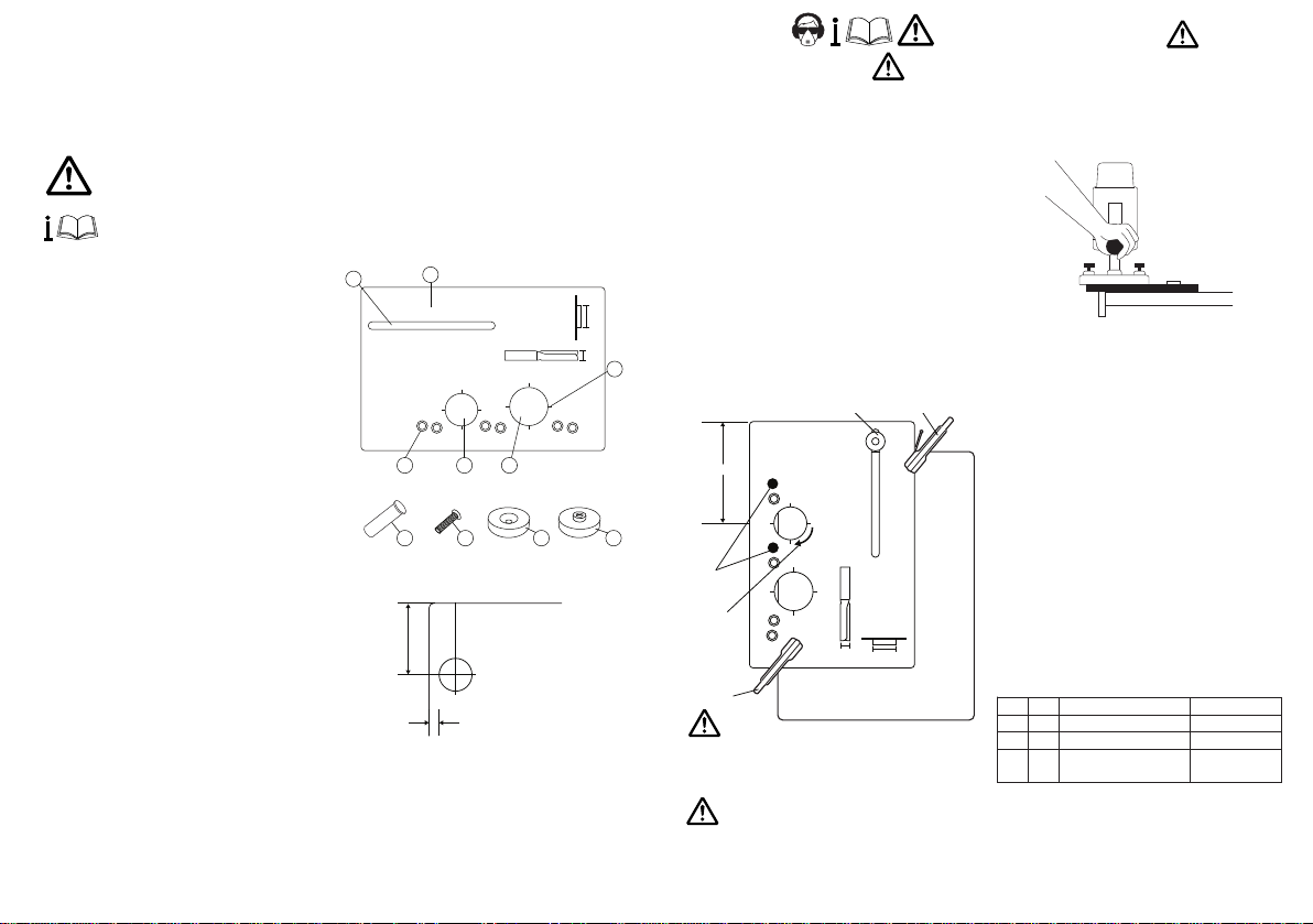
A. Template body x1
B. End stop slot
C. 26mmØ hinge hole recess aperture
D. 35mmØ hinge hole recess aperture
E. Line-up pins x4
F. End stop csk threaded x1
G. End stop threaded x1
H. Machine screw csk M5 x 25mm x1
I. Line-up pin holes for 3mm or 5mm offset
J. Sight lines
K. Instructions x1
B
A
30 mm12.7 mm
35 MM
26 MM
5 MM
5 MM
3 MM
C
I
5 MM
3 MM
3 MM
D
I H F G
Hole Position Range
26mmØ
50-105mm
36mmØ
50-190mm
3mm
or
5mm
Assembly
n If the edge guide assembly is not already fitted
to the template, then fit countersink machine
screw into countersink head end stop guide and
tighten with a screwdriver.
n Place end stop and screw into end stop slot and
fit the other end stop. Tighten screw with
a screwdriver.
OPERATION
Marking Out & Clamping
n Check which size hinge recess you need and
mark the position of the hinges on the door. The
centre of each hole should be 100mm from the
top and bottom of the door respectively, to give
the required support. Ensure this measurement
is as accurate as possible.
n Choose between a 3mm or 5mm gap from the
edge of the circular recess. Position the locating
pins in the chosen holes.
n Butt the line-up pins up against the edge of the
door and the end stop bush against the top of
the door. Line up the centre of the hole with the
100mm mark on the door, and tighten the end
stop in position using a screwdriver.
n Clamp the template securely in place. Ensuring
the clamps will not foul the router path.
n Ensure the router is isolated from the power
supply before making any adjustments. Fit the
J
cutter and guide bush.
n Set the depth of cut to 10mm.
End stop
assembly
100mm
5 MM
3 MM
26 MM
5 MM
3 MM
Line-up
pins
Feed
direction
Clamp
Consider working environment before using
tools. Keep proper footing and balance at all
times.
The material being cut, along with the template
will need to be supported and clamped securely.
Ensure the clamps will not foul the router base
and that the worktop is placed at a comfortable
working height.
35 MM
3 MM
5 MM
Clamp
30 mm12.7 mm
Routing the Recesses
n Place the guide bush in the aperture of the
template, switch on the router, plunge down
and lock plunge lever/knob.
n Rout out the recess. Ensure the material is
cleared out of the inside of the recess as well
as round the edge.
n Increase the cut depth by 2mm to 12mm
maximum and rout the recess again. This should
be enough clearance for most hinges. Adjust
this depth if you require holes for thicker hinge
heads.
n Once routing of recess is complete, release
plunge and switch off the router.
n Release the clamps and repeat for the
second hinge.
n If middle hinges are needed remove end stop
assembly and position template accordingly.
After use, store template carefully.
ACCESSORIES
Please use only Trend original accessories.
Ref. GB30 Guide bush 30mm diameter.
Ref. 3/08X1/4TC 12.7mm diameter router cutter.
3/83DX1/2TC
Ref. UNIBASE Sub-base to accept guide bush
for certain makes and models
of router.
SPARE PARTS
Please use only Trend original spare parts.
Item Qty. Desc. Ref. (1 off)
E 1 Line-up Pins (4 Pack) KWS/PIN/4
- 1 End Stop Assembly WP-HJ/B/05
H 1 Machine Screw WP-SCW/86
M5 x 20mm Csk Pozi®
 Loading...