

TREND TB/TS/KO, TB/TS/OS, TB/TS/KOS, TB/TS/KOF, TB/TS/KOSF Installation Instructions Manual
Page 1
TB/TS/KO, /OS, /KOS, /KOF, /KOSF Installation Instructions TG200606 Issue 3, 26-Aug-2014 1
Installation Instructions
TB/TS/KO, /OS, /KOS, /KOF, /KOSF
Thermistor Room Temperature Sensors
Important: Retain these instructions
These instructions shall be used by trained service personnel only
If th e equ ipm ent is used in a manner not specied by these instr uctions, the pr otection provided by the equipment may be impaired.
1
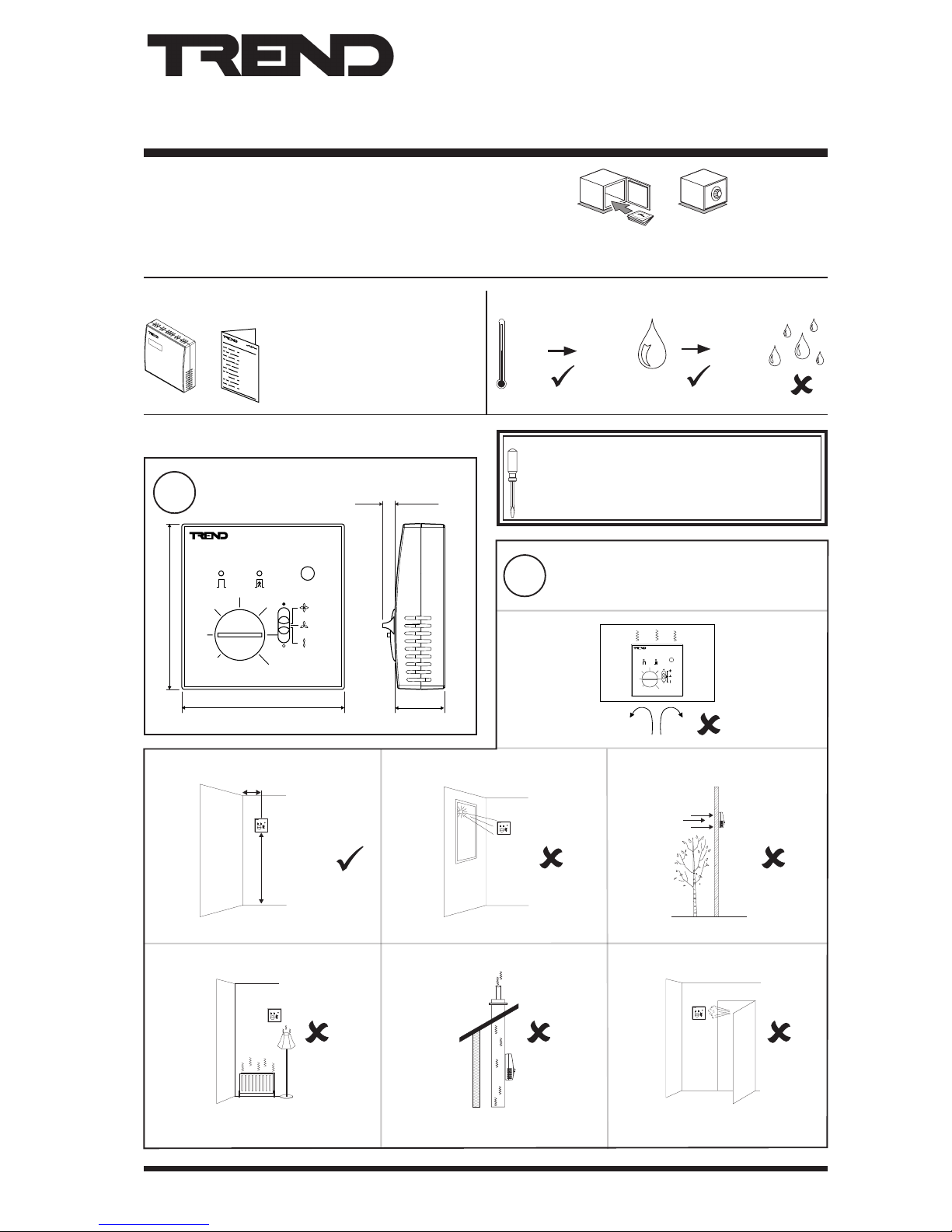
Dimensions
2
Mounting Requirements
3 INSTALLATION
1 BOX CONTENTS 2 STORING
It is recommended that the installation should comply
with the local electrical safety installation practices (e.g.
HSE Memorandum of Guidance on Electricity at Work
Regulations 1989, USA National Electric Code).
-
+
85 mm (3.35”)
26 mm (1.02”)
85 mm (3.35”)
6 mm (0.24”)
-
+
> 50 cm (20”)
1.5 m
(5 ft)
TB/TS/KO, /OS, /KOS, /KOF, /KOSF
Installation Instructions (TG200606)
HO
2
+50 °C
(122 °F)
0
-10 °C
(14 °F)
90 %RH
Page 2
2 TB/TS/KO, /OS, /KOS, /KOF, /KOSF Installation Instructions TG200606 Issue 3, 26-Aug-2014
TB/TS/KO, /OS, /KOS, /KOF, /KOSF Installation Instructions
3
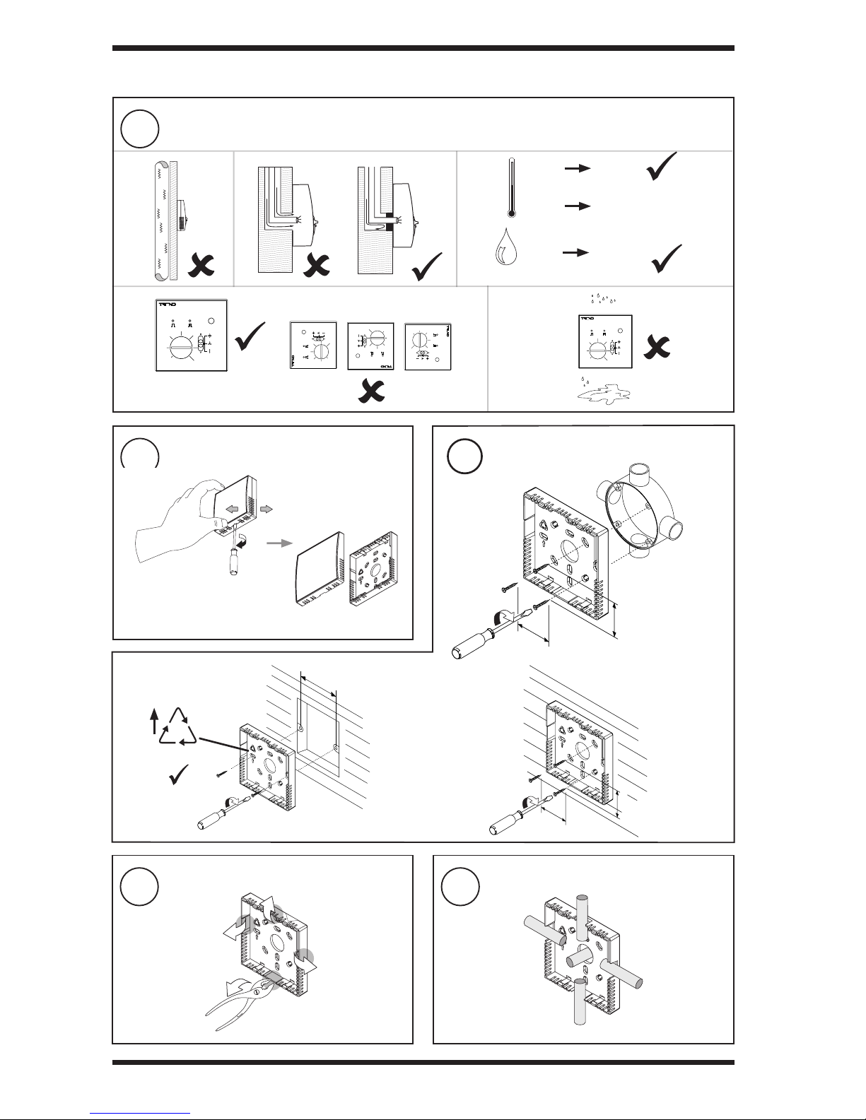
Requirements (continued)
3
Remove backplate Mount backplate
4
5
Remove Cutout(s)
6
Route cables
3 INSTALLATION (continued)
HO
2
-
+
-10 °C
(14 °F)
+50 °C
(122 °F)
0 %RH
90 %RH
or wall
BESA box
35 mm
(1.3 8” )
60 mm (2.36”)
wall box
as required
0 °C
(32 °F)
+40 °C measurment
(104 °F)
35 mm
(1.3 8” )
35 mm (1.38”)
35 mm (1.38”)
-
+
-
+
-
+
-
+
FR
ABS
Page 3
TB/TS/KO, /OS, /KOS, /KOF, /KOSF Installation Instructions TG200606 Issue 3, 26-Aug-2014 3
Installation Instructions TB/TS/KO, /OS, /KOS, /KOF, /KOSF
9
Set up strategies
8
Assemble unit
3 INSTALLATION (continued)
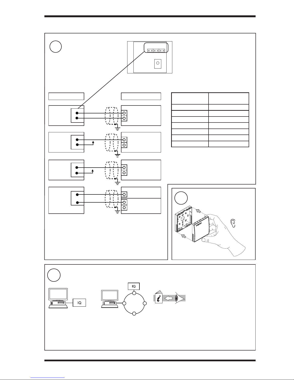
Wire to controller
7
*** Note that /KO, /OS, /KOS, /KOF, /KOSF cannot
be used by IQ211 (although they can be used by
IQ212)
TB/TS Data Sheet (TA200603)
or
For /KO, /OS, /KOS, /KOF, /KOSF options congure the
controller strategy using the pre-congured strategy in SET’s
Strategy Librar y (TB TS KOSF), and only use the options
required.. If this is not used write your own strategy, see data
sheet for suggested strategy.
1 2 3 4 5 6
Note that these options (TB/TS/KO, /OS,
/KOF, /KOSF) cannot be used with IQLs;
use options TB/TS, TB/ TS/K, /KE, or /KEF
with IQLs.
OPTION
CONNECT
TERMINALS
TB/TS 1, 2
TB/TS/K 1, 2, 3
TB/TS/KO*** 1, 2, 3, 4**
TB/TS/OS*** 1, 2, 3*, 4**
TB/TS/KOS*** 1, 2, 3, 4**
TB/TS/KOF*** 1, 2, 3, 4**, 5, 6
TB/TS/KOSF*** 1, 2, 3, 4, 5, 6
Terminal size 0.5 to 2.5 mm2 (20 to 14 AWG)
Note that the IQ recommended limits may need to be changed
to suit mains supply voltage and auxiliary supply loading, or a
24 Vdc regulated supply can be used.
‘click ’
4
3
5
6
OUT
0 V
IN
COM (0 V)
+24 V
IN
COM (0 V)
SENSOR
/K, /O
/S
/F
analogue input
(thermistorT)
auxiliary supply
analogue output
(voltage V)
analogue input
(voltage V)
see note ** below
Knob/Override
Status/Power
+24 V
Fan
IQ
1
2
IN
TB/TS
analogue input
(thermistorT)
COM (0V)
0V
Temperature
1
1
* Note that the override function operates via the knob connection so
that for the /OS option, the Knob connection must be made.
**Note that the override function takes its power from the Status/
Power connection so the Status/Power connection (terminal 4) must
also be made for /KO and /KOF versions. For these /KO and /KOF
versions, connect the Status/Power to 10 Vdc or 24 Vdc. If status
indication is tted but not used (i.e. /OS, /KOS, /KOSF used as /O,
/KO, or /KOF), 10 Vdc must be used e.g. from dummy analogue
output.
IQecos with xed strategies must be
connected as described in the relevant
strategy data sheet.
For IQecos with xed strategies ignore steps 9 and 10 and proceed to step 11
Page 4
4 TB/TS/KO, /OS, /KOS, /KOF, /KOSF Installation Instructions TG200606 Issue 3, 26-Aug-2014
TB/TS/KO, /OS, /KOS, /KOF, /KOSF Installation Instructions
Please send any comments about this or any other Trend technical publication to [email protected]
© 2014 Honeywell Technologies Sàrl, ECC Division. All rights reserved. Manufactured for and on behalf of the Environmental and Combustion Controls
Division of Honeywell Technologies Sàrl, Z.A. La Pièce, 16, 1180 Rolle, Switzerland by its Authorized Representative, Trend Control Systems Limited.
Trend Control Systems Limited reserves the right to revise this publication from time to time and make changes to the content hereof without obligation
to notify any person of such revisions or changes.
Trend Control Systems Limited
Albery House, Springeld Road, Horsham, West Sussex, RH12 2PQ, UK. Tel:+44 (0)1403 211888 Fax:+44 (0)1403 241608 www.trendcontrols.com
Trend Control Systems USA
6670 185th Avenue NE, Redmond, Washington 98052, USA. Tel:(425) 897-3900 Fax:(425) 869-8445 www.trend-americas.com
11
Test system
10
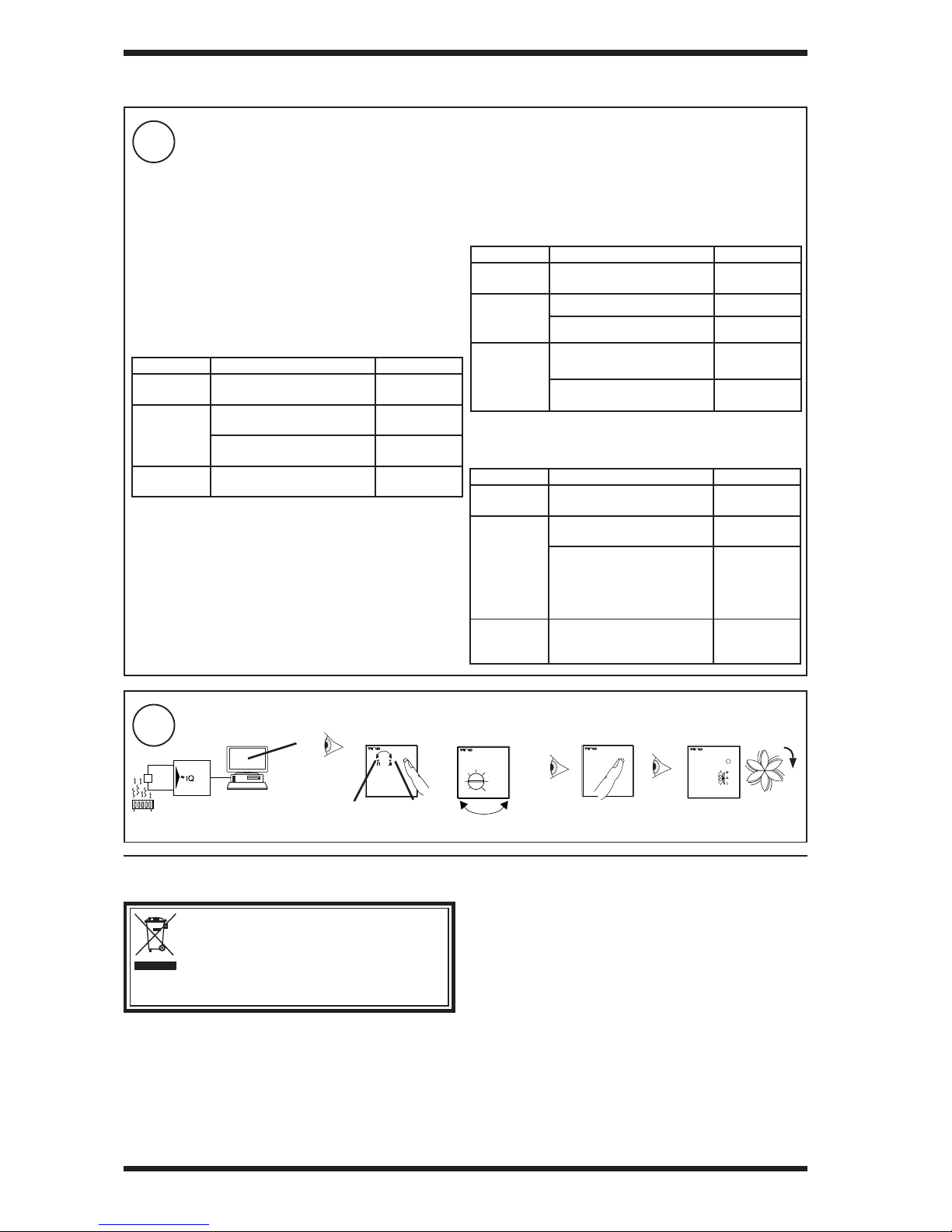
Set up IQ Sensor Types
4 DISPOSAL
WEEE Directive:
At the end of their useful life the packaging and
product should be disposed of by a suitable
recycling centre.
Do not dispose of with normal household waste.
Do not burn.
For IQ2 version 2.1 or greater, IQ3, IQ4, and IQeco, the
recommended method of setting the sensor scaling is to use
the ‘Unique Sensor Reference’ provided in SET, see below
for details.
For IQ1, IQ2 Version 2.0 or lower, see Sensor Scaling
Reference Card TB100521A, and set up manually in SET.
The input channel must be set to the appropriate input type (see controller documentation for details) and the sensor
type module must be set up with the correct scaling. If the SET pre-dened strategy is used the sensor scaling will
have been set up.
-
+
/K
/O
/F
/OS
∆ T
∆ SP
∆
yellow green
3 INSTALLATION (continued)
Knob: The input channel used should be set for thermistor
(T), and sensor scaling set as below.
Controller Unique Sensor Reference Notes
IQ1, IQ2 v2.0
or lower
Set up manually in SET
IQ2 v2.1 or
greater, IQ3,
and IQ4
Knob TB 3 deg trim Guaranteed ±3
trim
Knob T 3 deg trim ±3 ±20% linear
trim
IQeco (Knob TB 05 deg trim)
Type 102 - Potentiometer
-0.5 to + 0.5
deg trim
Thermistor: The input channel used should be set for
thermistor (T), and sensor scaling set as below.
Controller Unique Sensor Reference Notes
IQ1, IQ2 v2.0
or lower
Set up manually in SET
IQ2 v2.1 or
greater, IQ3,
and IQ4
Thermistor TBTS Value in °C
Thermistor TBTS F Value in °F
IQeco (10k Therm DegC TBTS)
Type 101 - Thermistor °C
Value in °C
(10k Therm DegC TBTS)
Type 108 - Thermistor °F
Value in °F
Fan Control: The input channel should be set for voltage (V),
and sensor scaling set as below.
Controller Unique Sensor Reference Notes
IQ2 v2.0 of
lower
Set up manually in SET
IQ2 v2.1 or
greater, IQ3,
and IQ4
Fan Control V produces
range 0 to 9.7
Fan KO enum produces fan
speed settings
for /O sensors
- see TB/TS
data sheet
IQeco (Fan TBTS KOF)
Type 111 - TBTS Fan Speed
Control
For TBTS
KOF, KOSF
 Loading...