

Page 1
Thermistor Room Temperature Sensors
Important: Retain these instructions
UNPACKING
INSTALLATION
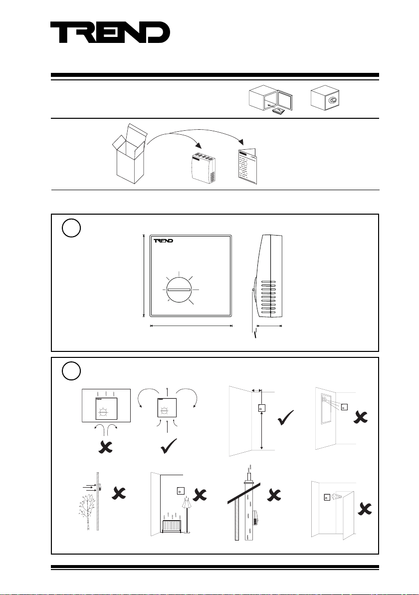
Dimensions
1
85 (3.35”)
-
+
Installation Instructions
TB/TS/K
TB/TS/K Installation
Instructions TG200607
85 mm (3.35”)
Requirements
2
a
- +
d
TB/TS/K Thermistor Room Temperature Sensors Installation Instructions TG200607 Issue 1/D 29/03/07
- +
e
b
f
26 mm (1.02”)
4 mm (0.16”)
> 50 cm (20”)
c
1.5 m
(5 ft)
g
1
Page 2
TB/TS/K Installation Instructions
- +
- +
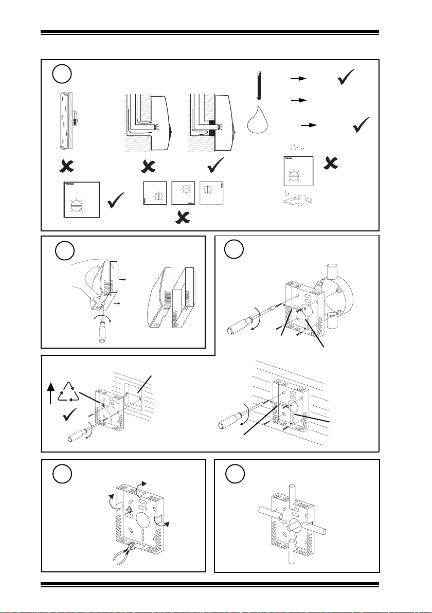
INSTALLATION (continued)
2
h
l
- +
3
a
wall box fascia
Requirements (continued)
i
- +
Remove backplate
b
60 mm (2.36”)
4
BESA box
or wall
j
-10 °C
(14 °F)
0 °C
(32 °F)
0 %RH
H O
2
l
- +
Mount backplate
35 mm (1.38”)
+50 °C
(122 °F)
+40 °C measurment
(104 °F)
90 %RH
35 mm (1.38”)
FR
ABS
35 mm (1.38”)
35 mm (1.38”)
Remove cutout(s)
5
as required
2
TB/TS/K Thermistor Room Temperature Sensors Installation Instructions TG200607 Issue 1/D 29/03/07
6
Route cables
Page 3
Installation Instructions TB/TS/K
1
3
2
INSTALLATION (continued)
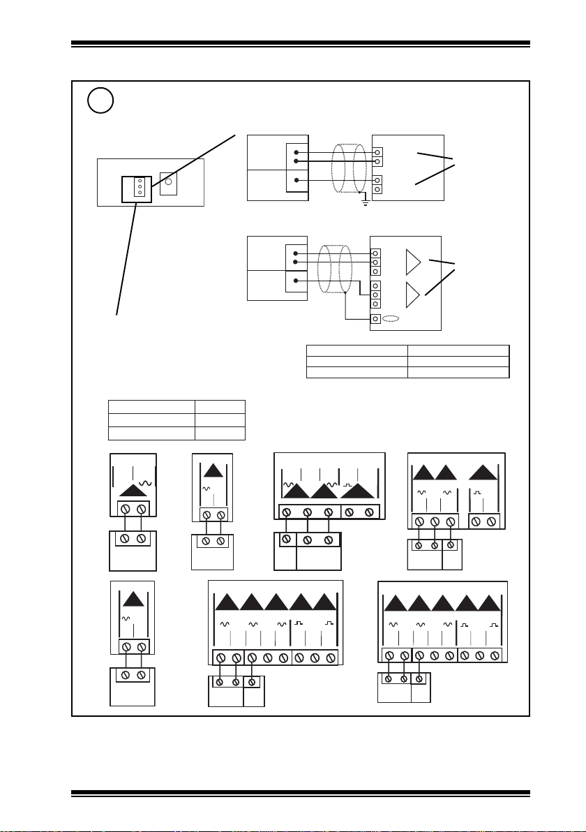
Wire to controller
7
2
Terminal size 0.5 to 2.5 mm
(14 to 20 AWG)
1 2 3
if IQ
S E N S O R
T B / T S
/ K
0 V
1
T e m p e r a t u r e
2
K n o b
3
C O M ( 0 V )
I N
I N
C O M ( 0 V )
I Q 2
analogue inputs
linked for
thermistor (T)
S E N S O R
1
T B / T S
2
3
/ K
if IQL
Note that screened cable is not required for sensor
wiring to IQLs. If screened cable is used, the
screen must be terminated at the controller to its
supply cable earth.
I Q L 1 0 / 2 4 V A C
910
C O M
21
TB/TS
I Q L 1 2 , 1 4
1
C O M
2 1 2 2
LQISNOITPO
ST/BT
41,21,01LQI
71,61,+51,+31,+11LQI
K/ST/BT,ST/BT
I Q L 1 0 / 2 3 0
1
C O M
1 5 1 6
1
2
TB/TS
1
C O M
/K
I Q L 1 3 + , 1 5 + , 1 6
2 3 4
C O M
2 1 2 2 2 3 2 4 2 5 2 6 2 7 2 8
0 V
T e m p e r a t u r e
K n o b
I Q L 1 1 + / 2 4 V A C
9 1 011 1 1 2
C O M
321
TB/TS
5
C
I Q 3
0 ( 0 V )
N ( i n )
N
+ ( + 2 4 V )
0 ( 0 V )
N ( i n )
N + 1
+ ( + 2 4 V )
NOITPOSLANIMRETTCENNOC
ST/BT2,1
K/ST/BT3,2,1
I Q L 1 1 + / 2 3 0
1 3
C
1
C O M
1 5 1 6 1 7 1 8 1 9
2
1
TB/TS
I Q L 1 7
1
2 3 4
C O M
A I
0 V
2 1 2 2 2 3 2 4 2 5 2 6 2 7 2 8
analogue inputs
linked for
thermistor (T)
2 3
3
/K
5
1 0 V
C
C
2
1
TB/TS
2
TB/TS
1
3
/K
TB/TS/K Thermistor Room Temperature Sensors Installation Instructions TG200607 Issue 1/D 29/03/07
2
TB/TS
1
3
/K
3
Page 4
TB/TS/K Installation Instructions
INSTALLATION (continued)
Assemble unit
8
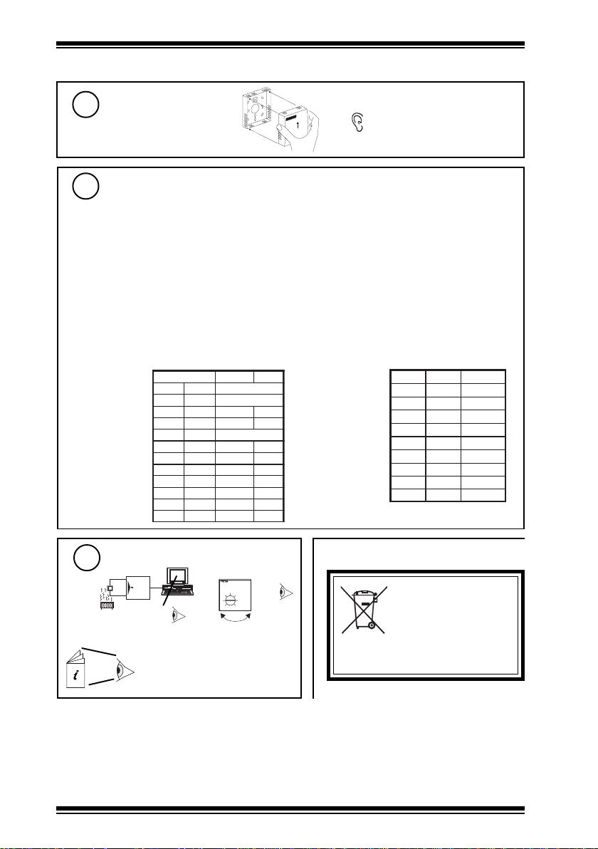
Set up IQ Sensor types
9
If IQ controller
It is recommended to use SET (software tool) for the setting of sensor type modules. For all IQ2
series controllers with firmware version 2.1 or greater, or IQ3 series controllers, select the
appropriate SET Unique Sensor Reference from the following:
Knob: Knob TB 3 deg trim (guaranteed ±3 trim)
Thermistor: Thermistor TBTS (°C)
If not using SET, use the following tables for all IQ2 series controllers of firmware version 2.1
or greater or IQ3 controllers, and set mode to 5 (characterise); for all other IQ controllers see Sensor
Scaling Reference Card TB100521A.
Thermistor
(0 to +40 °C)
alternatively: Knob T 3 deg trim (±3 ±20% linear)
Thermistor TBTS F (°F)
(change the values of U and L to those in the following table)
)stlovrotsimreht(1
Knob
(trim -3 to +3)
stinU
Y
E
U
L
P
xxI)C°(xO)F°(xO
1
2
3
4
5
6
C°F°
epyttupnI
3
tnenopxE
05221
reppU
rewoL
5-32
stnioP
6
146.205221
74.304401
64.40368
366.60105
866.7023
201.85-32
‘click’
Y
E
U
L
P
xxIxO
1
2
3
4
epyttupnI
tnenopxE
reppU
rewoL
stnioP
59.1.3-
50.13-
59.83+
50.311.3+
)smhoK(3
1
2.3
2.3-
4
10
If IQ
If IQL
Test system
I Q
Δ T
IQL Strategy Installation
/K
Δ SP
- +
DISPOSAL
WEEE Directive :
At the end of their useful life the
packaging and product should be
disposed of by a suitable recycling
Do not dispose of with normal household waste.
Do not burn.
centre.
Instructions
Manufactured for and on behalf of the Environmental and Combustion Controls Division of Honeywell Technologies Sàrl, Ecublens, Route
du Bois 37,Switzerland by its Authorized Representative, Trend Control Systems Limited.
Trend Control Systems Limited reserves the right to revise this publication from time to time and make changes to the content hereof
without obligation to notify any person of such revisions or changes.
Trend Control Systems Limited
P.O. Box 34, Horsham, West Sussex, RH12 2YF, UK. Tel:+44 (0)1403 21888 Fax:+44 (0)1403 241608 www.trend-controls.com
Trend Control Systems USA
6670 185th Avenue NE, Redmond, Washington 98052, USA. Tel: (425)897-3900, Fax: (425)869-8445 www.trend-controls.com
4
TB/TS/K Thermistor Room Temperature Sensors Installation Instructions TG200607 Issue 1/D 29/03/07
 Loading...