

Page 1
Important: Retain these instructions
UNPACKING
Installation Instructions
T/AV
Averaging Temperature Sensor
INSTALLATION
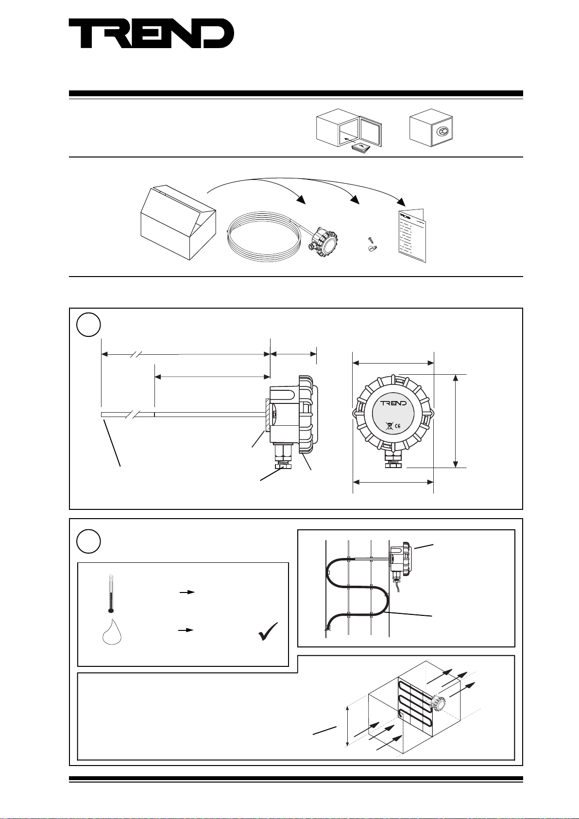
Dimensions
1
3.5 m (3.8 yds) (/S) or 7.0 m (7.7 yds) (/L)
Flexible copper tube
Rigid stainless steel tube
100 mm (3.94”)
Foam gasket
M16 cable gland
57 mm
(2.24”)
IP67 (NEMA 6)
housing
/S 6 off
/L 12 off
97 mm (3.82”)
T/AV-S
TrendControl SystemsHorsham
Madein theEU
85 mm (3.35”)
centres
T/AV Installation
Instructions 91-2511
105 mm (4.13”)
Requirements
2
a
H O
Ensure no stratification (e.g. downstream of mixing valves,junctions)
T/AV Averaging Temperature Sensor Installation Instructions 91-2511 Issue 3 27/06/08
measurement ranges
-10 °C
+14 °F
0 %RH 95 %RH
2
Protection :IP67, NEMA6
+110 °C
+230 °F
minimum distance from junctions =10xd.
b
c
d
-40 °C to +50 °C
-40 °F to +122 °F
-10 °C to +110 °C
+14 °F to +230 °F
1
Page 2
T/AV Installation Instructions
INSTALLATION (continued)
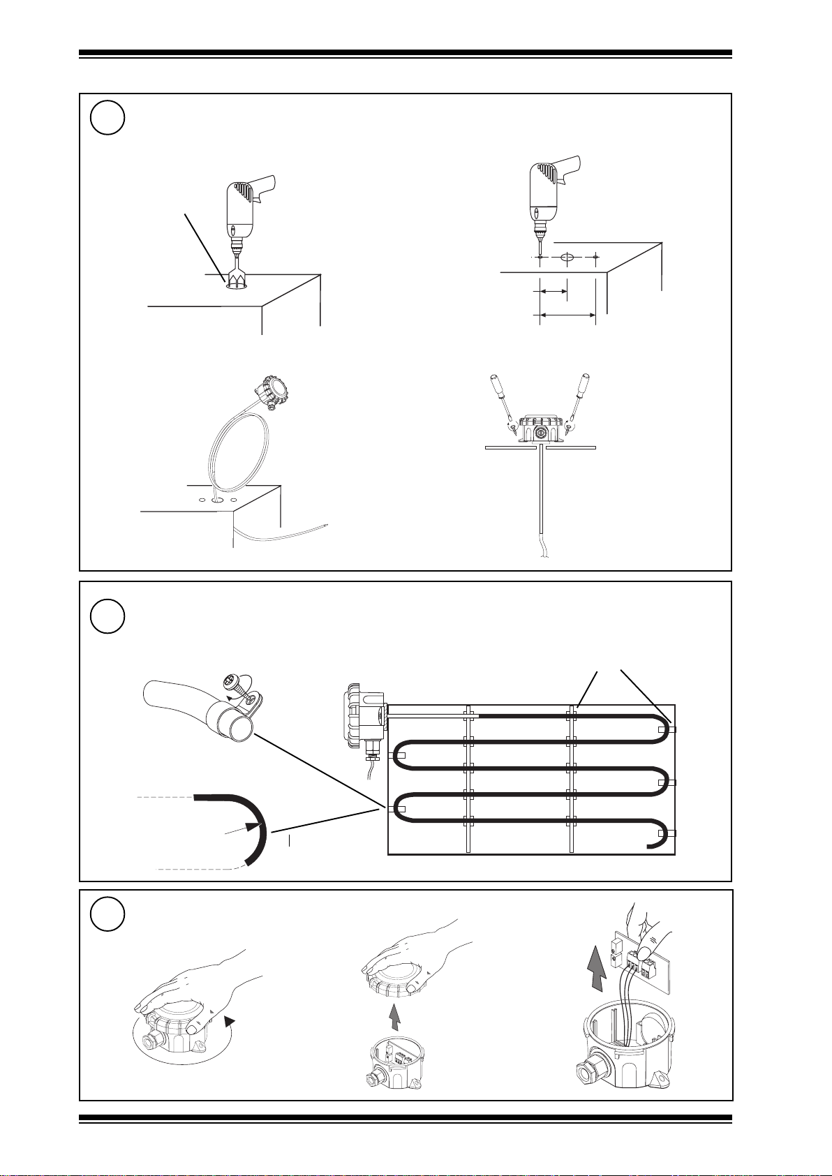
3
a
•Ø 7mm (0.28”)
c Uncoil sensor tube and feed into duct
Mount on sensor on duct
Drill hole in duct
b
d
Drill 2 holes
2 off
42.5mm (1.67”)
85mm (3.35”)
4
5
Mount sensor tube in duct
Remove lid and lift up board
a
/S 6 off
/L 12 off
clips
R< 10cm (3.94”)
c
b
1 - 2
T/AV Averaging Temperature Sensor Installation Instructions 19-2511 Issue 3 27/06/08
Page 3

Installation Instructions T/AV
INSTALLATION (continued)
6
7
Insert cable
Use M16 cable gland
Wire to controller
Sensor
+
Caution: This unit contains static
damage to the units. BS EN100015/1
Basic Specification: protection of
electrostatic sensitive devices.
-
sensitive devices. Suitable
anti-static precautions
should be taken throughtout
the operation to prevent
IQ1xx, IQ2xx
24 Vdc
IN
I
polarity independent
(ignore +/-)
Sensor
IQ system TP/I/22/HF/200 (Belden
8761) cable recommended.
Terminal size 0.5 to 2.5 mm2 (14 to 20
AWG)
Note that if connecting to an IQ22x controller (including /ADL or /OC), do not connect directly to C (+24V), instead
connect to AUX+ (+24V).
8
Replace board and lid
a
b
Terminate screen at IQ end only
+
-
IQ3
0 (0 V)
N (in)
+ (24 V)
c
Analogue input channel
linked for current (I)
N
T/AV Averaging Temperature Sensor Instructions 19-2511 Issue 3 27/06/08
1 - 3
Page 4

T/AV Installation Instructions
INSTALLATION (continued)
9
10
It is recomended to use SET (software tool)for setting of the sensor
type module. For all IQ2 series controllers with firmware version 2.1
or greater, or IQ3 series controllers, the SET Unique Sensor Reference
should be used:
Alternatively set scaling mode to 5 (characterise) and enter scaling
manually as defined in the table opposite. Note that for IQ3 the scaling
mode and exponent do not need to be set up.
For all other IQ controllers see Sensor Scaling Reference Card
TB100521A.
Configure IQ
or
I Q
Set up sensor type
PRT I -10+110 (°C)
PRT I +14+230F (°F)
I Q
IQ Configuration Manual 90-1533
IQ3 Configuration Manual TE200768
PRT sensor (-10°C + 110°C, +14°F +230°F)
Y
E
U
L
P
x
1
2
epyttupni)tnerruc(2
tnenopxE3
stinUC°F°
reppU011032
rewoL01-41
stnioP22
xIxOxO
401-41
02011032
Test system
11
IQ
ΔT
DISPOSAL
WEEE Directive :
At the end of their useful life the packaging and
product should be disposed of by a suitable
Do not dispose of with normal household waste.
Do not burn.
Please send any comments on this or any other Trend technical publication to techpubs@trendcontrols.com
© 2008 Honeywell Technologies Sàrl, ECC Divison. All rights reserved. Manufactured for and on behalf of the Environmental and Combustion Controls
Division of Honeywell Technologies Sàrl, Ecublens, Route du Bois 37, Switzerland by its Authorized Representative,
Trend Control Systems Limited reserves the right to revise this publication from time to time and make changes to the content hereof without
obligation to notify any person of such revisions or changes.
Trend Control Systems Limited
P.O. Box 34, Horsham, West Sussex, RH12 2YF, UK. Tel:+44 (0)1403 211888 Fax:+44 (0)1403 241608 www.trend-controls.com
Trend Control Systems USA
6670 185th Avenue NE, Redmond, Washington 98052, USA. Tel: (425)897-3900, Fax: (425)869-8445 www.trend-controls.com
recycling centre.
4
T/AV Averaging Temperature Sensor Installation Instructions 91-2511 Issue 3 27/06/08
 Loading...