

Page 1
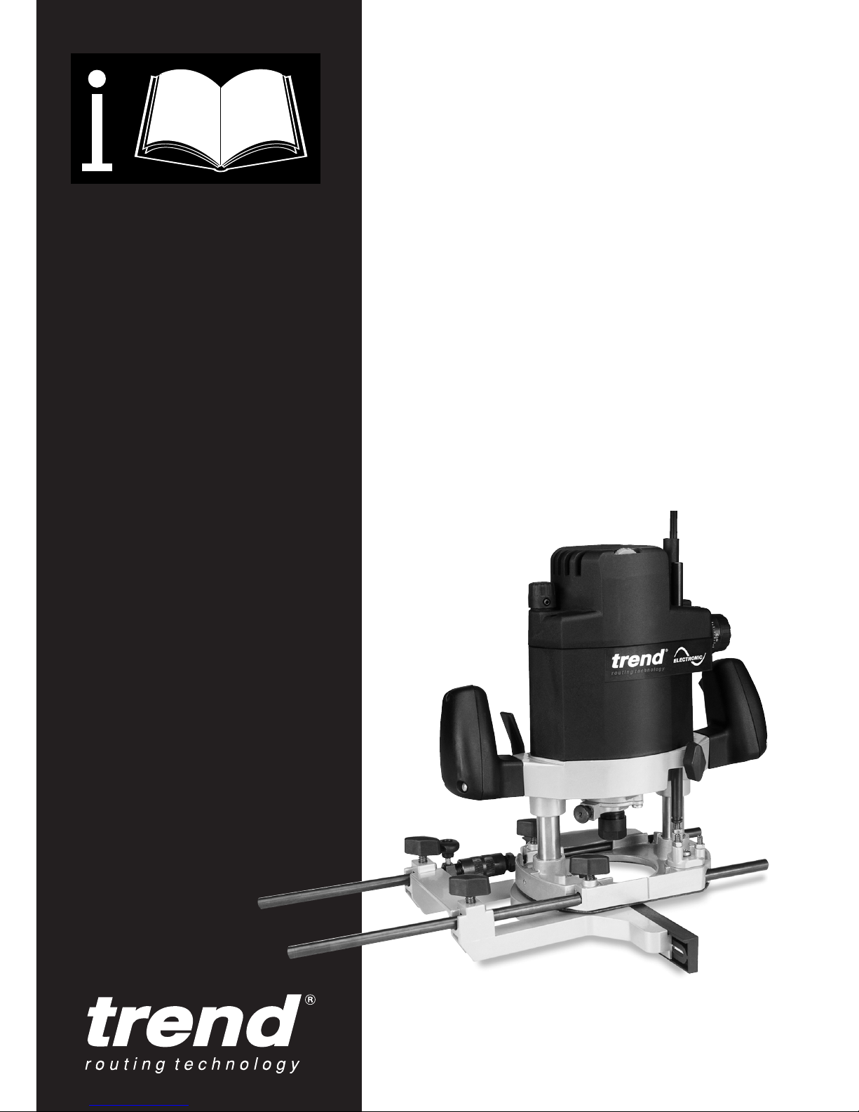
T9
Page 2

Dear Customer
Thank you for purchasing this Trend product, we
hope you enjoy many years of creative and
productive use.
Please remember to return your guarantee card
within 28 days of purchase.
CONTENTS
TECHNICAL DATA _____________________1
SAFETY ____________________________2-3
ELECTRICAL SAFETY _________________4
MANUFACTURERS DECLARATION ______5
ITEMS ENCLOSED ____________________5
DESCRIPTION OF PARTS_______________6
ASSEMBLY & ADJUSTMENT
– Dust Extractor Spout __________________7
– Switching On & Off____________________7
– Depth of Cut _________________________8
– Fitting & Removing Cutters _____________9
– Speed Control ______________________10
– Fine Height Adjuster _________________10
– Fixing Points________________________11
OPERATION
– Cutting Direction & Feed Speed ________12
– Side-fence Routing___________________13
– Template Guide Bush Fitment __________14
– Template Guide Bush Routing __________15
– Beam Trammel Routing _______________16
– Bearing Guided Cutters _______________17
– Freehand Routing ___________________18
– Batten Routing ______________________18
MAINTENANCE & CARE_______________19
RECYCLING _________________________19
GUARANTEE ________________________19
SPARE PARTS
– Spare Parts List _____________________20
– Spare Parts Diagram _________________23
T9
-1-
TECHNICAL DATA
Voltage: UK & Eire 230V
UK & Eire only 110V
Europe 230V
Power input 1800W
No load speed (min) 8,000-22,000 rpm
Router carriage 2 columns
Router carriage stroke 75mm
Revolver depth stop 3-step, turret stop
adjustment with
graduation
Collet size: UK & Eire
1
/4 inch (6.35mm)
&
1
/2 inch (12.7mm)
Europe: 8mm & 12mm
Cutter diameter, max 75mm
Weight 5.2kg
Fuse: UK & Eire 230V 13A in plug
UK & Eire 110V 16A in mains
Europe 230V 10A in mains
The following symbols are used throughout this
manual:
Denotes risk of personal injury, loss of life
or damage to the tool in case of nonobservance of the instructions in this
manual.
Denotes risk of electric shock.
If y
ou require further technical
information or spare parts, please call
our technical support department on
01923 224681.
Page 3

T9
-2-
SAFETY
Observe the safety regulations in the
i
nstruction manual of the Power Tool to
b
e used or connected to this
attachment. Also observe any
applicable additional safety rules. Read
the following safety instructions before
attempting to operate this product.
PLEASE KEEP THESE
INSTRUCTIONS IN A SAFE
PLACE.
The attention of UK users is drawn to
The Provision and Use of Work
Equipment Regulations 1998, and any
subsequent amendments.
General
n Disconnect power tool, when not in
use. Before servicing and when
changing accessories such as
cutters. Disconnect power tool and
attachment from power supply
.
Ensure the machine is switched off
before plugging tool in or
connecting to a power supply.
n Always mount the power tool,
accessory or attachment in
conformity with the present
instructions.
n Keep children and visitors away. Do
not let children or visitors touch the
tool, accessory or attachment.
Keep children and visitors away
from work area.
n Make the workshop child proof with
padlock and master switch.
n Dress properly. Do not wear loose
clothing or jewellery, they can be
caught in moving parts. Rubber
gloves and non-skid footwear is
recommended when working
outdoors. Wear protective hair
covering to contain long hair.
n Consider working environment. Do
not use the product in the rain or in
a damp environment. Keep work
area well lit. Do not use power tools
near gasoline or flammable liquids.
Keep workshop at a comfortable
temperature so your hands are not
cold.
n The accessory or attachment must
be kept level and stable at all
times.
n Keep work area clean. Cluttered
workshops and benches can cause
injuries
n U
se the attachment with the power
t
ools and accessories specified in
this manual only. Do not force the
tool or attachment to do a job for
which it is not designed.
n S
ecure idle tools. When not in use,
tools should be stored in a dry and
high or locked up place, out of
reach of children.
n F
or best control and safety use
both hands on the power tool and
a
ttachment. Keep both hands away
from cutting area. Always wait for
t
he spindle and cutter to stop
rotating before making any
adjustments.
n Always keep guards in place and in
good working order.
n Remove any nails, staples and
other metal parts from the
workpiece.
n Maintain tools and cutters with
care.
Keep cutters sharp and clean
for better and safer performance.
Do not use damaged cutters.
Follow instructions for lubricating
and changing accessories. Keep
handles dry, clean and free from oil
and grease.
n Maintain accessories. Do not use
damaged accessories. Only use
accessories recommended by the
manufacturer.
n Check damaged parts. Before
operation inspect the attachment,
the power tool, the cable, extension
cable and the plug carefully for
signs of damage. Check for
alignment of moving parts, binding,
breakage, mounting and any other
conditions that may effect its
operation. Have any damage
repaired by an Authorised Service
Agent before using the tool or
accessory.
n Do not use tool if switch does not
turn it on or off. Have defective
switches replaced by an Authorised
Service Agent.
n Don't over reach. Keep proper
footing and balance at all times.
n Don’t abuse the cable. Never carry
power tool or accessory by cord or
pull it to disconnect from the
socket. Keep cord from heat, oil
and sharp edges. Always trail the
power cord away from the work
area.
n Connect dust extraction equipment.
If devices are provided for the
c
onnection of dust extraction and
c
ollection facilities, ensure these
a
re connected and properly used.
n Check all fixing and fastening nuts,
bolts and screws before use to
e
nsure they are tight and secure.
P
eriodically check when machining
over long periods.
n Stay alert. Watch what you are
d
oing. Use common sense. Do not
o
perate tools when you are tired,
under the influence of drugs or
alcohol.
n Personal Protective Equipment
(PPE). All PPE must meet current
UK and EU legislation.
n Do not leave tools running
unattended. Do not leave tool until
it comes to a complete stop.
n Always clamp workpiece being
machined securely.
n Only use cutting tools for
woodworking that meet EN847-1/2
safety standards, and any
subsequent amendments.
Routing Safety
n Disconnect router power tool.
When not in use, before servicing
and when changing accessories
such as cutters, disconnect router
and attachment from power supply.
n Ensure router cutter has stopped
rotating before changing it. Never
use the spindle lock as a brake.
n Remove adjusting keys and
spanners. Form the habit of
checking to see that keys and
adjusting spanners are removed
from the router tool, cutter and
attachment before turning router
on. Make sure cutter can rotate
freely.
n Check all ball bearing and blade
fixing screws before use to ensure
they are tight and secure.
Periodically check when machining
over long periods.
n When using a template guide bush
ensure it cannot come into contact
with collet and nut.
n Noise. Take appropriate measures
for the protection of hearing if the
sound pressure of 85dB(A) is
exceeded. Routing sound pressure
may exceed 85dB(A), so ear
Page 4

T9
-3-
p
rotection must be worn.
n Eye protection. Wear safety
goggles, spectacles or visors to
p
rotect the eyes from ejected
w
aster particles.
n Respiratory protection. Wear a face
o
r dust mask, or powered
r
espirator. Dust masks/filters should
b
e changed regularly.
n Do not switch router on with the
cutter touching the workpiece.
n T
he direction of routing must
a
lways be opposite to the cutter's
direction of rotation.
n After work, release the router
plunge and allow spindle to stop
rotating before putting machine
down.
n Check before cutting that there are
no obstructions in the path of the
router. When cutting through the full
thickness of the workpiece, ensure
there are no obstacles beneath
workpiece, and that a sacrificial
work surface is used.
Additional Safety Rules For
Router Cutters
n Cutting tools are sharp. Care
should be taken when handling
them.
n Always use cutters with a shank
diameter corresponding to the size
of the collet installed in your tool.
n Always run router cutters at the
spindle speed recommended and
marked accordingly. Ensure cutter
has reached correct speed before
entering workpiece. Recommended
speeds can be found on the
packaging, in cutter instructions or
in the Trend Routing Catalogue.
n Always use router cutters in a
router. Router cutters must not be
used in a drill. Drill and boring bits
must not be used in a router.
Router cutters must only be used
for the material cutting application
for which they are designed. Do not
use on metal or masonary.
n Never use cutters with a diameter
exceeding the maximum diameter
indicated in the technical data of
the powertool or attachment used.
n Do not drop cutters or knock them
against hard objects. Do not use
cutters that are damaged.
n Cutters should be kept clean. Resin
build up should be removed at
regular intervals with Resin
Cleaner®. The use of a dry
l
ubricant (Trendicote
®
P
TFE) will
a
ct as a preventative. Do not use
PTFE spray on plastic parts.
n Cutter shanks should be inserted
into the collet to the mark line on
the shank. This ensures that at
least
3
⁄4of the shank length is held
in the collet. Do not over-tighten the
c
ollet nut as this will score the
s
hank and create a weakness and
f
racture point.
n Observe the correct assembly
instructions in the router instruction
manual for fitting the collet and nut.
Observe the router power tool
manual instructions on fitting
cutters correctly.
n It is advisable to periodically check
the collet and collet nut. A worn,
distorted or damaged collet can
cause vibration and damage the
shank, and should be replaced.
Worn collet nuts should be
replaced.
n Do not take deep cuts in one pass;
take several shallow or light passes
to reduce the side load applied to
the cutter
. Too deep a cut in one
pass can stall the router.
n Very small diameter cutters must
be handled and used with care.
n Always return cutter to its
packaging after use.
n Should you experience excessive
vibration during use stop
immediately. Have the eccentricity
of the router, router cutter and
clamping system checked.
n All fastening screws and nuts
should be tightened using the
appropiate spanner or key in
accordance with the manufacturers
instructions.
Using Routers In A Fixed
Position
n After work, release the router
plunge to protect the cutter
.
n Always use a push-stick or push-
block for last 300mm of the cut.
n Whenever possible use a work
holding device or jig to secure
component being machined.
n Ensure attachment is securely fitted
to the workbench, with table
surface at approximately hip height.
n E
nsure a No-Volt Release Switch is
f
ixed to or adjacent to the
attachment and that it is used
correctly.
n C
heck the direction of the
workpiece is always opposite to the
c
utter's direction of rotation.
n D
o not use awkward or
u
ncomfortable hand positions.
n Do not reach underneath table or
put your hands or fingers at any
time in the cutting path while tool is
c
onnected to a power supply.
Useful Advice When Routing
n Judge your feed rate by the sound
of the motor. Feed the router at a
constant feed rate. Too slow a feed
rate will result in burning.
n Take many light passes rather than
one deep cut to reduce the side
load applied to both router and
router cutter
.
n Trial cuts should be made on waste
material before starting any project.
n When using some attachments
including a router table or dovetail
jig, the use of a fine height adjuster
is highly recommended.
n When using a template guide bush,
ensure there is sufficient clearance
between cutter tip and inside edge
of bush. Ensure cutter and guide
bush are concentric.
Router Cutter Maintenance
n Composite cutting tools (brazed tip)
must be maintained by a competent
person i.e. a person of training and
experience, who has knowledge of
the design requirements and
understands the levels of safety to
be achieved.
n The design of composite tools must
not be changed in the process of
maintenance.
n Replacement parts must meet
Trend specification.
n Tolerances which ensure correct
clamping by the collet shall be
maintained.
n When re-grinding the tool, care
must be taken not to cause
weakening of the body or the
connection between the cutting
edge and the body.
Page 5

Never use a light socket. Never
connect the live (L) or neutral (N)
wires to the earth pin marked E or .
Using an Extension Cable
n If an extension cable is required, use an
approved triple core extension cable suitable
for the power input of this tool (see technical
data).
n When using a cable reel, always unwind the
cable completely.
n Also refer to the table below.
Cable Rating (Amperes)
Voltage
110V 240V
7.5 15A 6A
15 15A 6A
25 20A 6A
30 25A 6A
45 25A 10A
60 25A 15A
Conductor size Cable rating
(mm2) (Amperes)
0.75 6
1.00 10
1.50 15
2.50 20
4.00 25
For 115V units with a power rating exceeding
1500W we recommend to use a plug to BS4343
standard.
T9
-4-
Mains Plug Replacement
(UK & Ireland only)
Always check the condition of the cable and plug
before starting with your work.
Should your mains plug need replacing and you
are competent to do this, proceed as instructed
below. If you are in doubt, contact an authorised
Trend repair agent or a qualified electrician.
n Disconnect the plug from the supply.
n Cut off the plug and dispose of it safely; a
plug with bared copper conductors is
dangerous if engaged in a live socket outlet.
n Only fit 13 Amperes BS 1363A approved
plugs fitted with a 13 Amp A.S.T.A approved
BS 1362 fuse (1).
n The cable wire colours, or a letter, will be
marked at the connection points of most good
quality plugs. Attach the wires to their
respective points in the plug (see below).
Brown is for Live (L) (2) and Blue is for
Neutral (N) (3).
n Before replacing the top cover of the mains
plug ensure that the cable restraint (4) is
holding the outer sheath of the cable firmly
and that the two leads are correctly fixed at
the terminal screws.
ELECTRICAL SAFETY
3
4
2
1
13 AMP
Power Supply
The electric motor has been designed for one
voltage only. Always check that the power
supply corresponds to the voltage on the rating
plate. Machines marked for 230 volt can also be
operated from a 220 volt supply.
The T9 is double insulated in
accordance with EN 50144; therefore no
earth wire is required.
Cable Length (M)
Page 6

T9
-5-
ITEMS ENCLOSED
1 x Parallel side-fence
2 x Adjustable fence cheeks
1 x Micro fence adjuster
1 x Collet
1
/4” (6.35mm) UK & Eire (Europe
8mm)
1 x Collet
1
/2” (12.7mm) UK & Eire (Europe
12mm)
1 x Spanner (22mm A/F)
1 x Inner plate and fixing screws
1 x Line up pin 12mm/
1
/2”
1 x Guide bush 30mm and fixing screws
1 x Dust extractor spout with adaptor and fixing
screws
1 x Fine height adjuster
1 x Instruction manual
1 x Guarantee registration card
T9E
MANUFACTURERS DECLARATION
We declare under our sole responsibility that
this product is in conformity with the
following standards of standardised
documents:
EN 50144, EN 55014, EN 60555, in
accordance with the 73/23/EEC directives
98/37/EC, 73/23/EEC, 93/68/EEC,
89/336/EEC.
Level of sound pressure according to
86/188/EEC & 89/392/EEC, measured
according to EN 50144:
Lpa (sound pressure) 85.5 dB(A)1
Lwa (acoustic power) 98.5 dB(A)2
Radio and TV suppression in compliance
with 76/889/EEC and 82/499/EEC
INFORMATION ON
NOISE/VIBRATION
The noise level when working
can exceed 85 dB(A).
Wear ear protection!
Weighted root mean square
acceleration value according to EN 50144:
< 2.5 (1.9) m/s2(hand arm method)
Managing Director
Stephen Phillips
Trend Machinery & Cutting Tools Ltd.
Page 7
T9
-6-
4
5
6
7
11
20
21
22
26
23
24
8
15
3
2
1
19
31
1425 1318 17
10
9
16
12
28
27
29
30
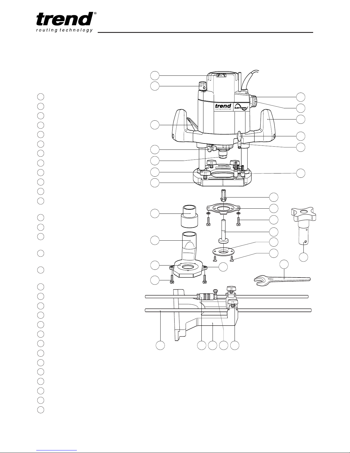
DESCRIPTION OF PARTS`
1 Plunge locking lever
2 Plunge depth adjustment knob
3 Variable speed control dial
4 Graduated ring
5 Depth stop adjustment knob
6 Thumb knob - depth stop
7 Depth stop
8 3 way turret stop
9 Collet nut
10
Spindle lock
11
Handle with on/off switch
12
Dust extractor spout
(internal dia. 35mm)
13
Micro fence adjuster thumb knob
14
Micro fence adjuster
15
Micro fence adjuster
base location
16
Thumb knob with anti-vibration
springs to secure side-fence rods
17
Thumb knob with anti-vibration
springs for side-fence
18
Side-fence
19
Spanner (22mm A/F)
20
Collet
21
Inner plate
22
Inner plate fixing screws and washers
23
Template guide bush dia 30mm
24
Template guide bush fixing screws
25
Fence rods dia 10mm x 450mm long
26
Template guide bush line up pin
27
Dust spout fixing screw
28
Dust spout adaptor (internal dia 26mm)
29
Dust spout insert
30
Dust spout fixing nut
31
Fine height adjuster
Page 8
T9
-7-
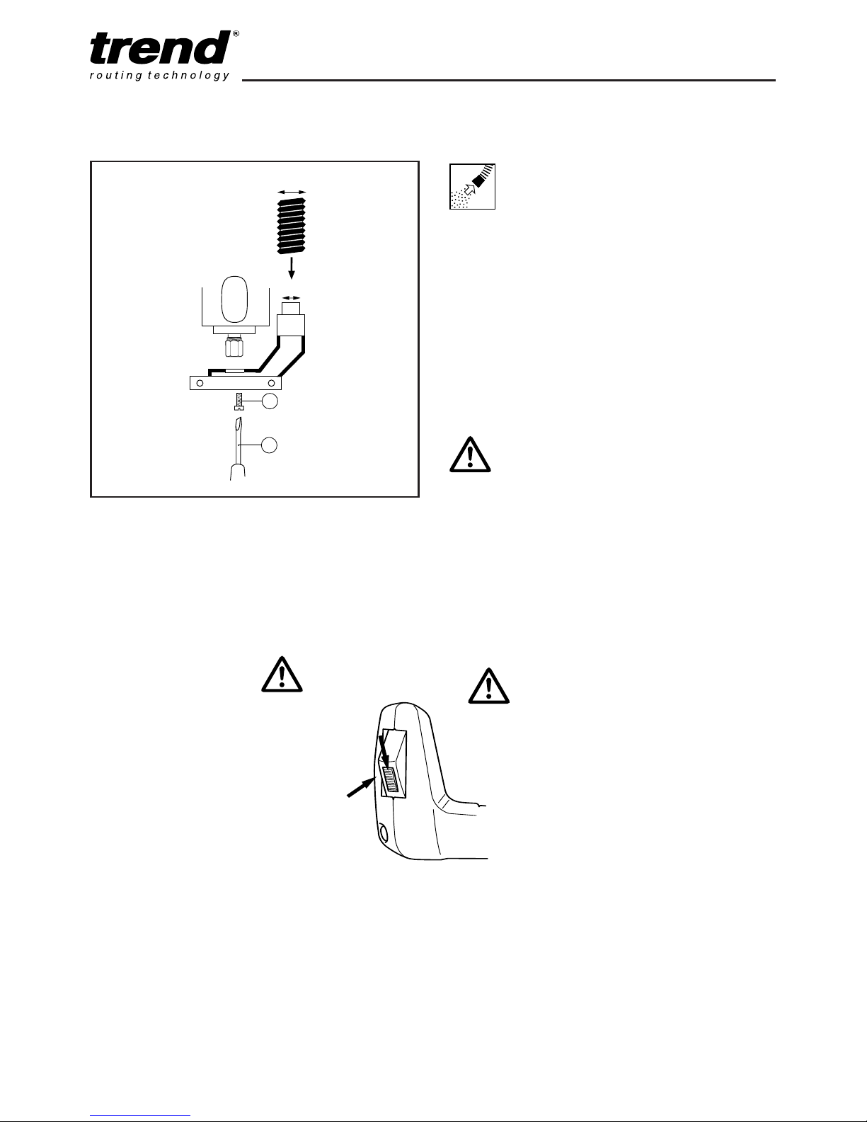
Fitting and Removing the
Dust Extractor Spout
n Insert the extractor spout in the routing base.
The extractor spout is suitable for dust
extractors with a hose diameter of 35mm.
A separate adaptor is supplied for use with
hose Ø 26mm.
n Gently fit the two machine screws (1) into the
captivated nuts in the spout from the
underside of the router. Using a screwdriver
(2), tighten the screws.
Dismantle in reverse order.
Whenever possible use the
dust extraction spout with a
suitable extractor when
routing.
35mm
26mm
1
2
F
itting Dust
Extractor
S
pout
ASSEMBLY & ADJUSTMENT
Switching On & Off
n The router is provided with
a safety device to prevent
the tool being switched on
accidentally. Before
squeezing the switch
trigger (B), it is necessary
to move the slide
downwards (A). To switch
off release trigger.
A
B
Make sure the trigger is not
depressed before connecting it to
the power supply!
Page 9
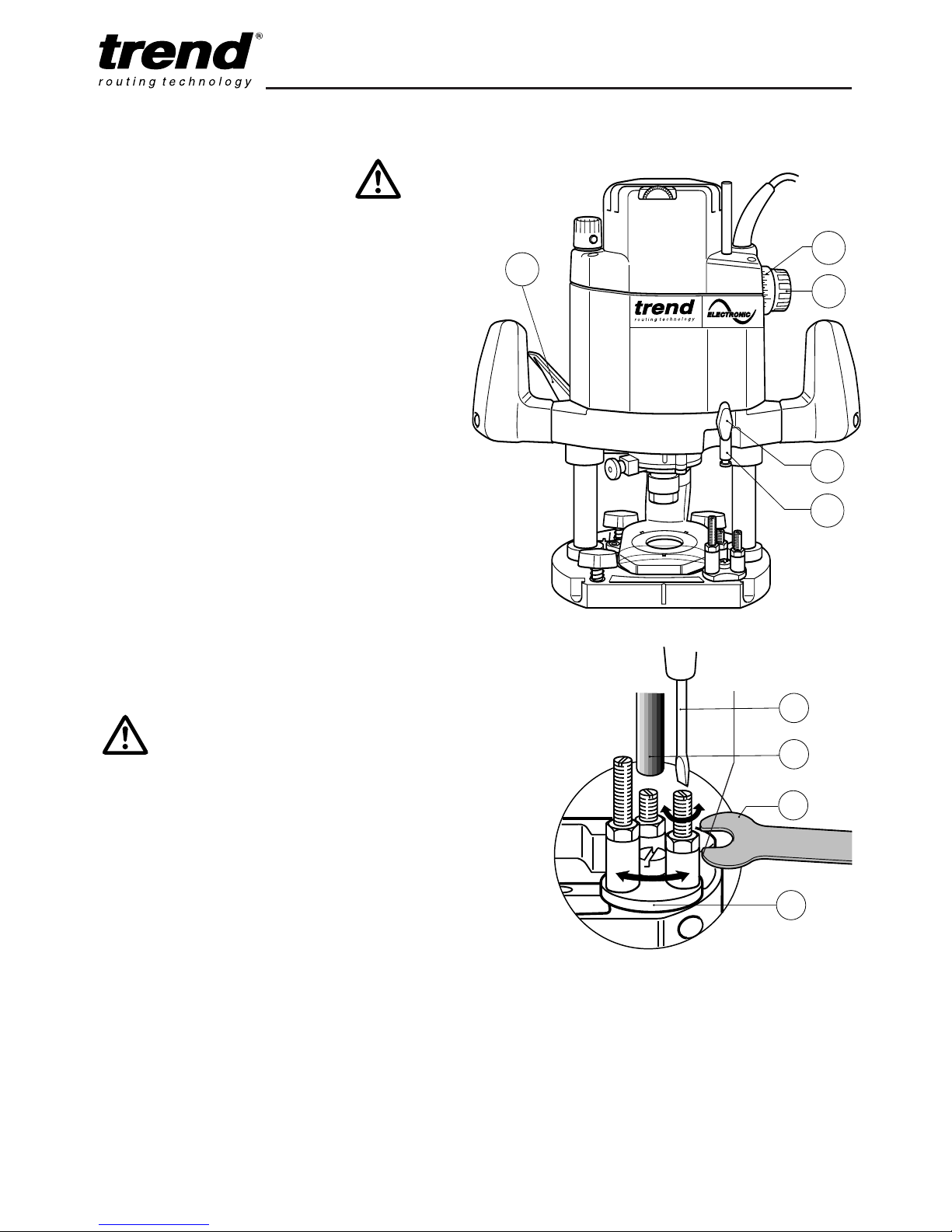
Adjusting the Depth of Cut
n Place the machine on the workpiece.
n Pre-set the 3-way turret stop (1) as required.
n Undo the thumb knob (2) for securing the
depth stop (3).
n Lift up the plunge locking lever (4) for fixing
the depth.
n Lower the machine slowly until the cutter
touches the workpiece and secure it with the
locking lever.
n
Set the graduated ring (5) to ‘0’ and by turning
the knob (6) raise the depth stop (3) by the
amount of required depth of cut (using the
graduation ring (5)).
n
One revolution of the knob (6) equals 25mm.
(Each single graduation equals a depth
adjustment of 0.5mm). Then re-tighten the
thumb knob (2).
The rotating turret stop screws can be used
for pre-setting up to three depths of cut.
Their
height can be adjusted using a screwdriver
(6) and an 8mm A/F spanner (7).
T9
-8-
1
6
3
7
By turning the turret stop, three depth settings
can be quickly made.
5
4
B
2
3
6
n Never make adjustments
when the router is running
or plugged in.
n Deep cuts should always be
routed in several passes.
Page 10
T9
-9-
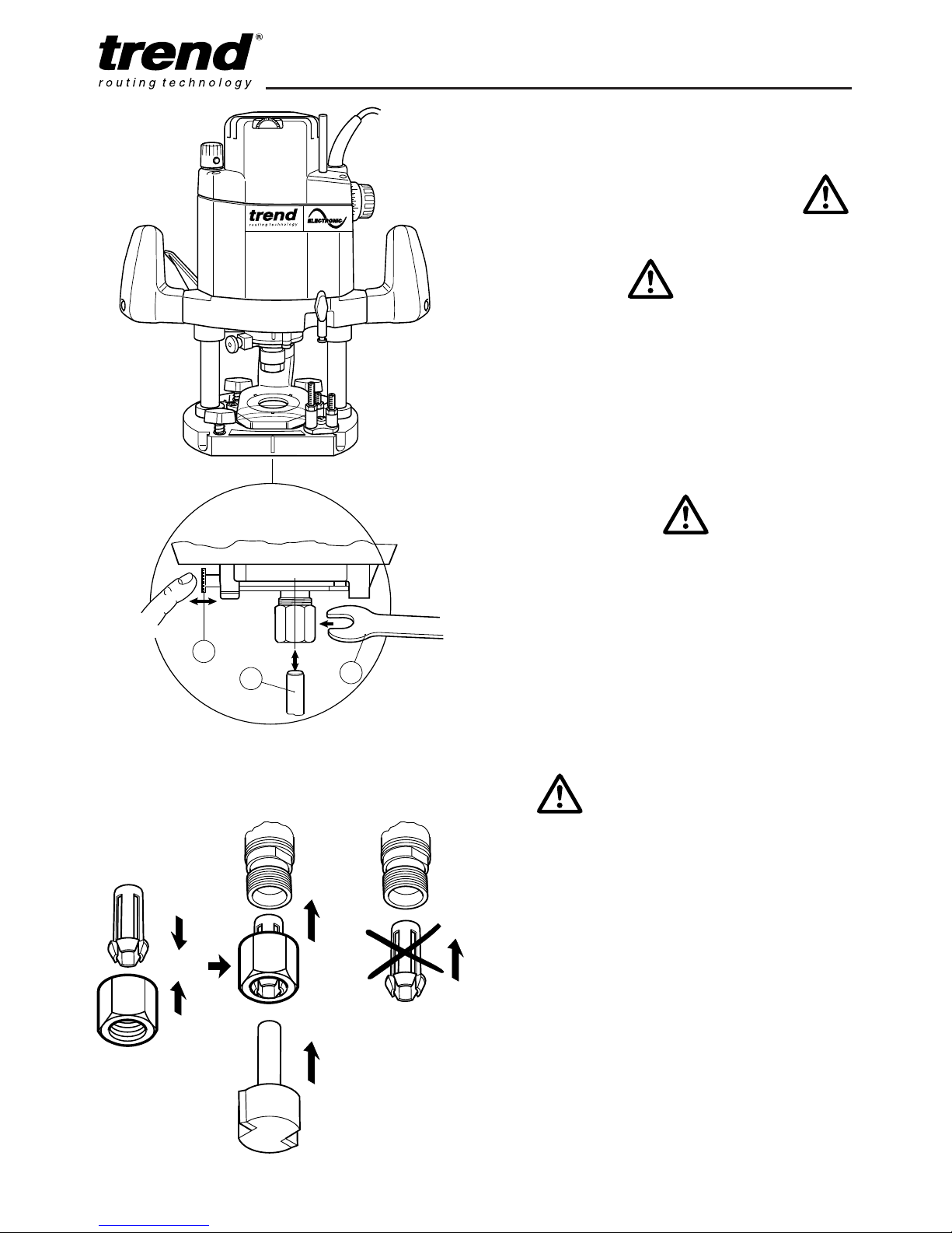
How to Fit and Remove a Router
Cutter
Fitting Cutters
n Insert at least 3/4 of the shank length of the
cutter (1) into the collet.
n Press the spindle lock (2) forward until the
router spindle is locked (you may need to turn
the spindle slightly to engage it).
n Tighten the collet nut with the spanner (3). Do
not use excessive force.
Removing Cutters
n Undo the 22mm A/F collet nut with the
spanner.
n Keep turning the spanner until the collet nut
tightens and then loosens again. This is the
fail-safe mechanism releasing the collet.
n The cutter should now slide out.
n Each time you finish using a cutter, remove it
and store it in a safe place.
2
1
3
CLICK
(2)
(3)
(1)
Correct Sequence for Fitting Collet,
Nut and Cutter
n Do not tighten the collet
without a cutter fitted.
n Always use cutters with
shanks which match the
diameter of the collet.
n Do not use cutters larger
than 45mm unless the router
is fitted in a router table.
Page 11
T9
-10-
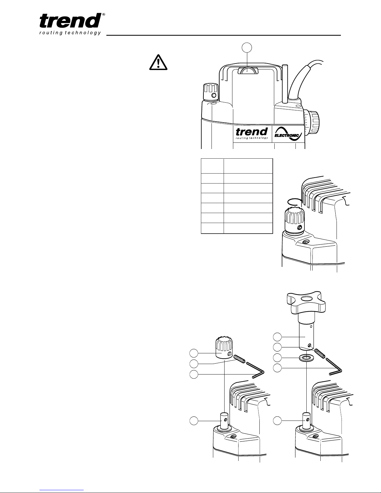
Setting the Electronic Speed
Control Dial
The speed is infinitely variable from 8,000 to
22,000 rpm using the electronic speed control
dial (1) for uniform cutting results in all types of
wood, plastics and in aluminium.
n Turn the electronic speed control dial to the
required level. The dial is numbered from 1 to
6 and corresponds to router speeds from
8,000 rpm to 22,000 rpm.
n Generally, use the lower settings for large
diameter cutters and the higher settings for
small diameter cutters. The correct setting will
also depend on the density of the material,
depth of cut and feed speed of the router, as
severe loss of rpm denotes motor overload.
Using the Fine Height Adjuster
The optional fine height adjuster
(ref. FHA/002) should be used when fine
adjustment is required. This is especially
recommended when using our dovetail jig or
router table.
Fitting the Fine Height Adjuster
n Lock depth of plunge with plunge locking
lever
n Using a Hex key (1) supplied with fine height
adjuster, remove grub screw (2) on the
plunge depth stop knob (3)
n Gently remove depth stop knob (3) from
height adjustment rod (4) by releasing the
plunge lever carefully. Once removed, plunge
router down and lock using plunge locking
lever.
n Fit washer (5) onto height adjustment rod (4)
and then fit height adjuster assembly (6) onto
height adjuster rod. Ensure that the hole in
both the assembly and rod are aligned.
n Using a Hex key (1) screw the grub screw (2)
into the threaded side of the fine height
adjuster body and into the thread within the
rod.
n Ensure grub screw (2) is not left proud.
Dial Router
No. Speed
1 8,000 rpm
2 10,000 rpm
3 12,000 rpm
4 15,500 rpm
5 18,000 rpm
6 22,000 rpm
1
3
2
1
4
4
1
5
2
6
4
1
5
2
6
Page 12

T9
-11-
Fixing Points for Accessories
The router has three threaded holes M6 in its
base that allow fitting of accessories and also
fitting to router tables.
A whole range of accessories are shown in the
Trend Routing Catalogue.
Stationary use
When the T9 is used in a stationary position with
a no volt release switch (ref. NVRS/230V or
NVRS/230V/EUR) fitted, a trigger lock (ref.
T9/LOCK) is available which will lock the trigger
in the ‘on’ position.
1
15mm
7
5mm
15mm
M6
The trigger lock must only be
used with the router in a
stationary position and with a
no volt release switch fitted.
Page 13
T9
-12-
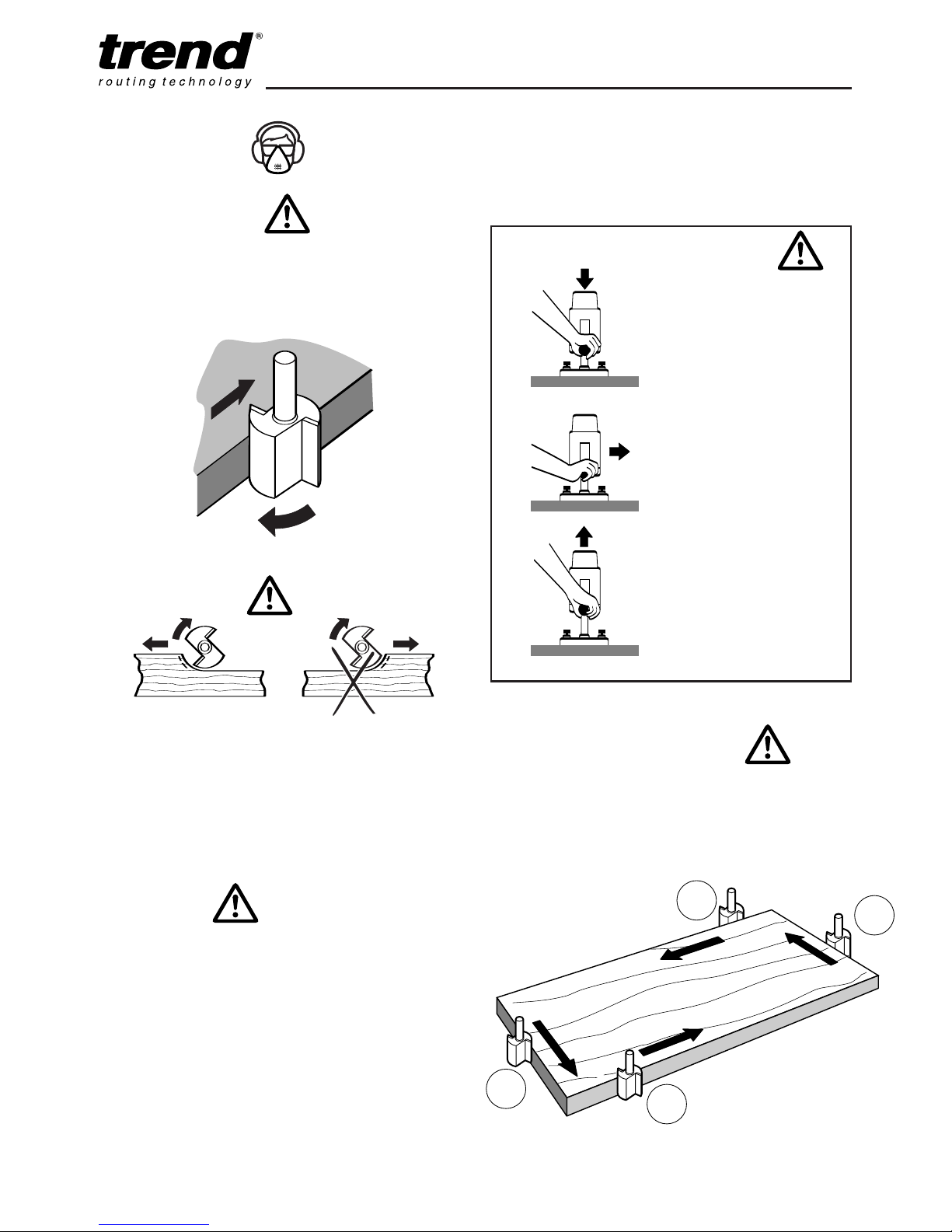
Step One
Plunge down and lock the
motor carriage, by
depressing the plunge
locking lever.
Step Two
Carry out the routing
operation.
Step Three
Release the plunge locking
lever and the motor carriage
returns to the normal
position.
Sequence of plunging
Feed Direction
When routing along an edge, the direction of the
router travel should be against that of the
rotation of the cutter. This will create the correct
cutting action and prevent the cutter ‘snatching’.
It will also pull the router towards the workpiece
and hence the side-fence or guide bearing will
be less likely to wander from the edge of the
workpiece.
Feed Speed
The speed at which the cutter is fed into the
wood must not be too fast that the motor slows
down, or too slow that the cutter leaves burn
marks on the face of the wood. Practice judging
the speed by listening to the sound of the motor
when routing.
OPERATION
Cutting Direction
The direction of routing must always
be opposite to the cutter’s direction of
rotation. Otherwise there is a risk of
kick-back.
Moulding Natural Timbers
When edge moulding natural timbers, always
mould the end grain first, followed by the long
grain. This ensures that if there is ‘breakout’, this
will be removed when the long grain is routed.
Feed direction
of router
Direction of
cutter rotation
1
3
4
2
Page 14
T9
-13-
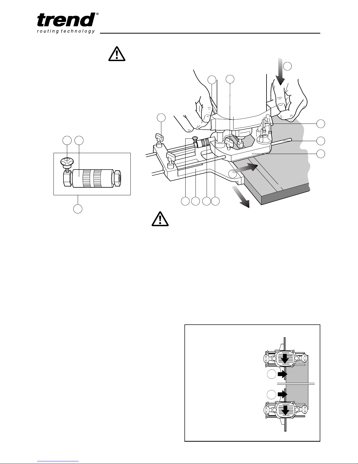
Side-fence Routing
The side-fence is used to guide the router when
moulding, edge profiling or rebating the edge of
the workpiece or when routing grooves and slots
in the centre of the workpiece, parallel to the
edge.
The edge of the workpiece must be straight and
true. The cheeks are adjustable and should
be set ideally with a 3–4mm gap each
side of the cutter.
4
3
218
5
6
1
1
7
10
B
A
1
8 9
C
D
When starting the cut, keep
the pressure on the front
cheek (C) until the back
cheek contacts the
workpiece edge.
At the end of the cut, keep
pressure on the back cheek
(D) until the cut is finished.
This will prevent the router
cutter swinging in at the end
of the workpiece and
‘nipping’ the corner.
Fitting the Micro Fence Adjuster
n Insert one end of the micro fence adjuster (1)
into one of the recesses (2) in the router
base (3)
n Fit the fence rods (4) into the side-fence (5).
Tighten thumb knob (6) on side-fence (5).
n Loosen thumb knobs (7) on router base (3)
and slide the side-fence (5) with its rods (4)
into the router base (3), one rod must also
pass through the micro fence adjuster
assembly (1).
n As long as the thumb knobs (7) on the router
base are loose the side fence (5) can be slid
in and out of the base of the router (3). This
allows approximate setting of the distance
between the cutter and the side fence cheeks.
n For fine adjustment of the distance, tighten
the micro fence adjustment knob (8) and turn
the micro fence adjustment barrel (9). One
revolution of the micro fence adjustment
barrel (9) equals 1.0mm side feed.
n When set, lock the side-fence in position
using the thumb knobs (7) on the router base
(3).
Using the Side Fence
n Lower the cutter onto the workpiece and set
the cutter height by raising the depth stop (10)
the required distance.
n Switch on the router and when the cutter
reaches full speed, release the plunge locking
lever (11), by lifting it up. Gently lower the
cutter into the workpiece and lock the plunge
locking lever (11) by depressing it.
n Feed along the timber, keeping sideways
pressure (A) to ensure the side-fence does
not wander away from the workpiece edge
and downward pressure on the inside hand
(B) to prevent the router from tipping.
n When finished, raise the router, secure with
plunge locking lever (11) and switch off.
Page 15
T9
-14-
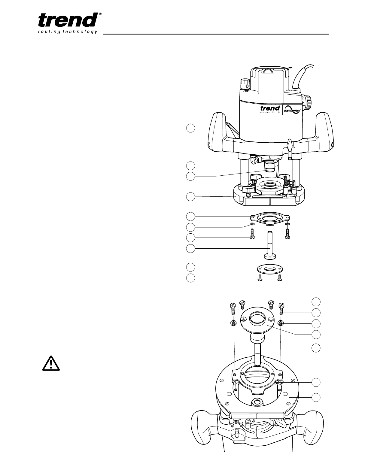
Fitting the Template Guide Bush and
Inner Plate
The T9 has a unique built-in line up system for
the template guide bush. This system ensures
that the guide bush is exactly concentric to the
router cutter to ensure accurate work.
n Turn the router upside down.
n Fit inner plate (2) with recess facing into the
recess in the router base plate (1) (raised side
away from router base). Loosely fit two pan
head machine screws (3) with split spring
washers (4) fitted through the inner plate and
screw into the base plate. DO NOT TIGHTEN.
n Fit the 30mm template guide bush (6) to the
raised side of the inner plate (2). Fit guide
bush with the two M5 countersink machine
screws (7). Tighten these screws.
n The line up pin (5) is stepped for 12mm and
1
/2” collet (8) sizes. (For the 1/2” collet simply
push the line up pin further down into the
1
/2”
collet).
n Fit line up pin (5) into the 1/2” collet (8) (or
12mm depending on the size fitted) in the
router, lightly tighten collet nut (9) to hold the
line up pin (5).
n Release plunge lever (10) and gently depress
base until line up pin (5) projects through the
30mm guide bush (6).
n Once in line, tighten the pan head machine
screws (3) with a flat screwdriver.
10
8
9
2
3
4
5
6
7
1
2
1
2
1
5
7
3
4
6
Reverse
view
When routing always lock the
plunge locking lever.
Page 16
T9
-15-
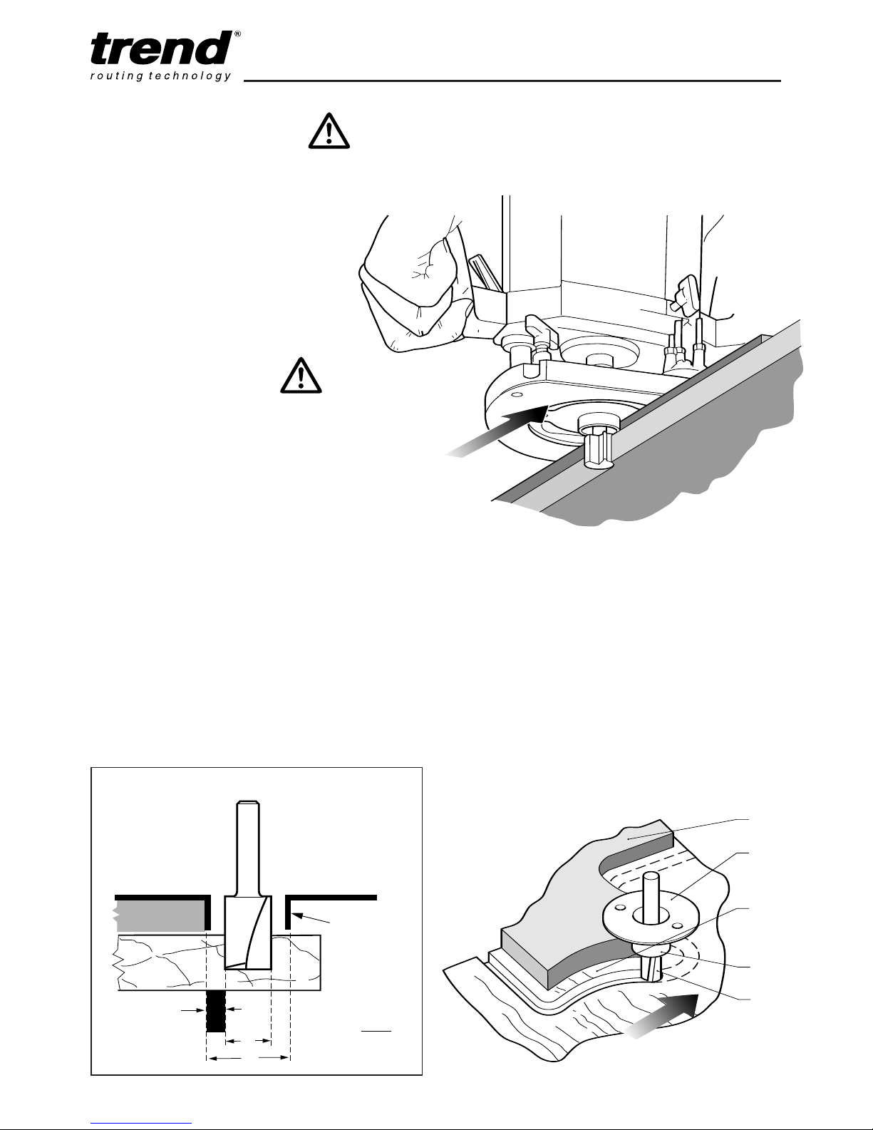
Guide bush
fitted to
router
E
d
D
Template
FORMULA
(D -d)
E =
2
Routing with a Template
The guide bush is used in conjunction with a
template when the routing operation is repetitive
or the workpiece is complex in shape. The
template is fixed to the upper surface of
the workpiece. A cutter is chosen with a
diameter which will pass through the
centre of the bush leaving enough
clearance. The cutter can be straight
or shaped. The router can then be
guided around the template so that the
shape of the template will be replicated.
Making the Template
The template is cut from 6mm or 1/4” MDF,
plywood or plastic to the shape required. The
guide bush offset needs to be allowed for when
calculating the shape of the template. The
template must be smaller by an amount equal to
the difference between the ‘outer edge of the
guide ring’ and the ‘outer edge of the cutter’.
See below for the offset calculation. The edge of
the template must be free of imperfections as
these will be replicated in the final workpiece.
Calculations for template offset
Template
Template
guide bush
Workpiece
Guide
bush ring
Cutter
Alternatively it can
be used for cutting
shapes or making
panelling grooves.
Using a template to rout a straight edge
Page 17
T9
-16-
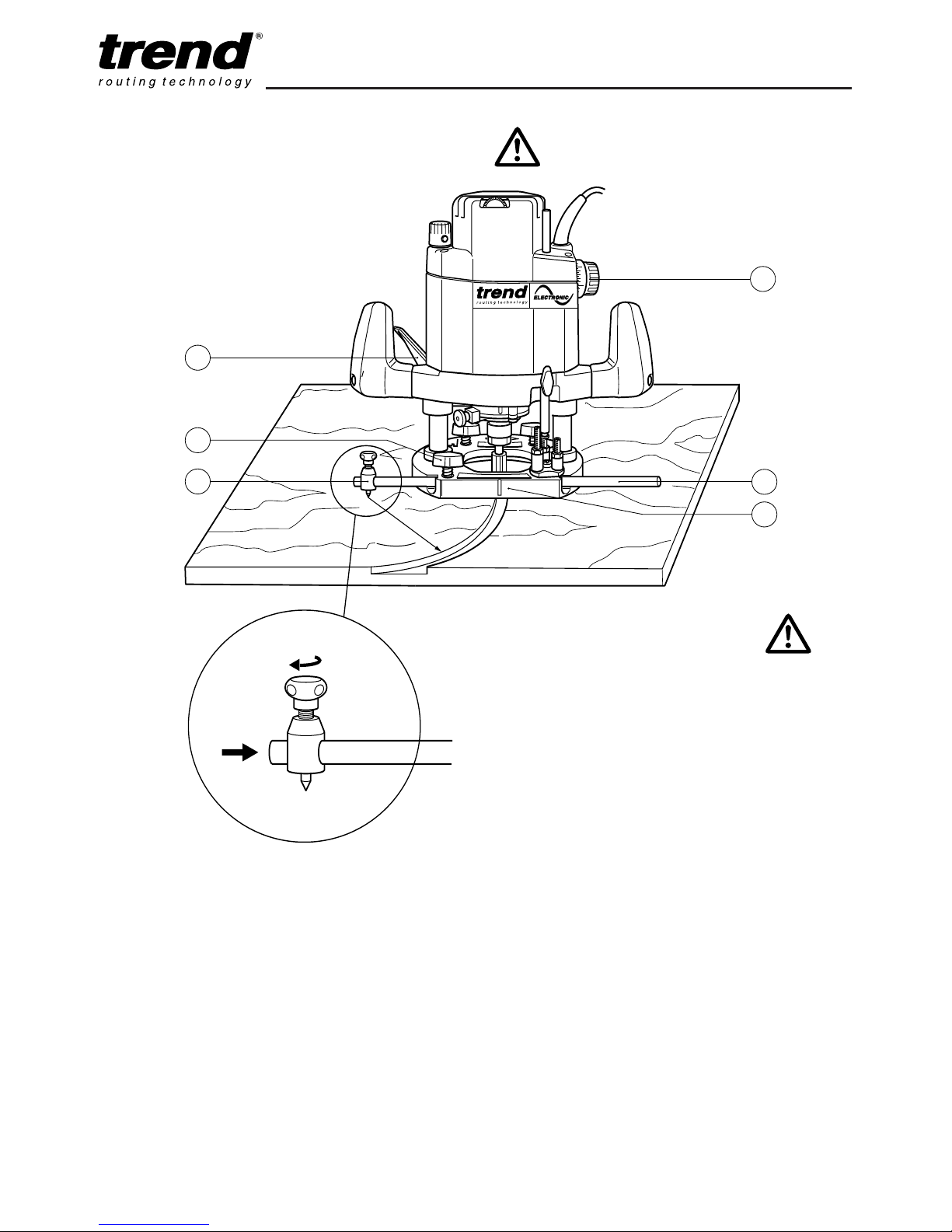
Beam Trammel Routing using Accessory
Ref. BEAM/009
Cutting Arcs with the Router
n Place the machine on the workpiece.
n Set the cutting depth using the depth stop
dial (2).
n Fasten the fence rod (1) in the routing base
(3) with the thumb knob (4).
n Fit on the beam trammel (5) as shown.
n Measure the radius and fix the point of the
beam trammel in position.
n Switch on the machine.
n After releasing the plunge locking lever (6),
lower the machine slowly as far as the depth
stop and lock it there.
n Cut grooves, rebates etc. at a steady rate of
feed, in an anti-clockwise direction. Ensure
the beam trammel point does not move.
n When finished, release plunge locking lever
(6) to raise the machine.
n Switch off the machine.
Fitting the Beam Trammel Attachment
n Fit the beam trammel attachment (A) on to
one rod and tighten the knob (B) securely.
A
B
2
1
3
4
5
6
Page 18
T9
-17-
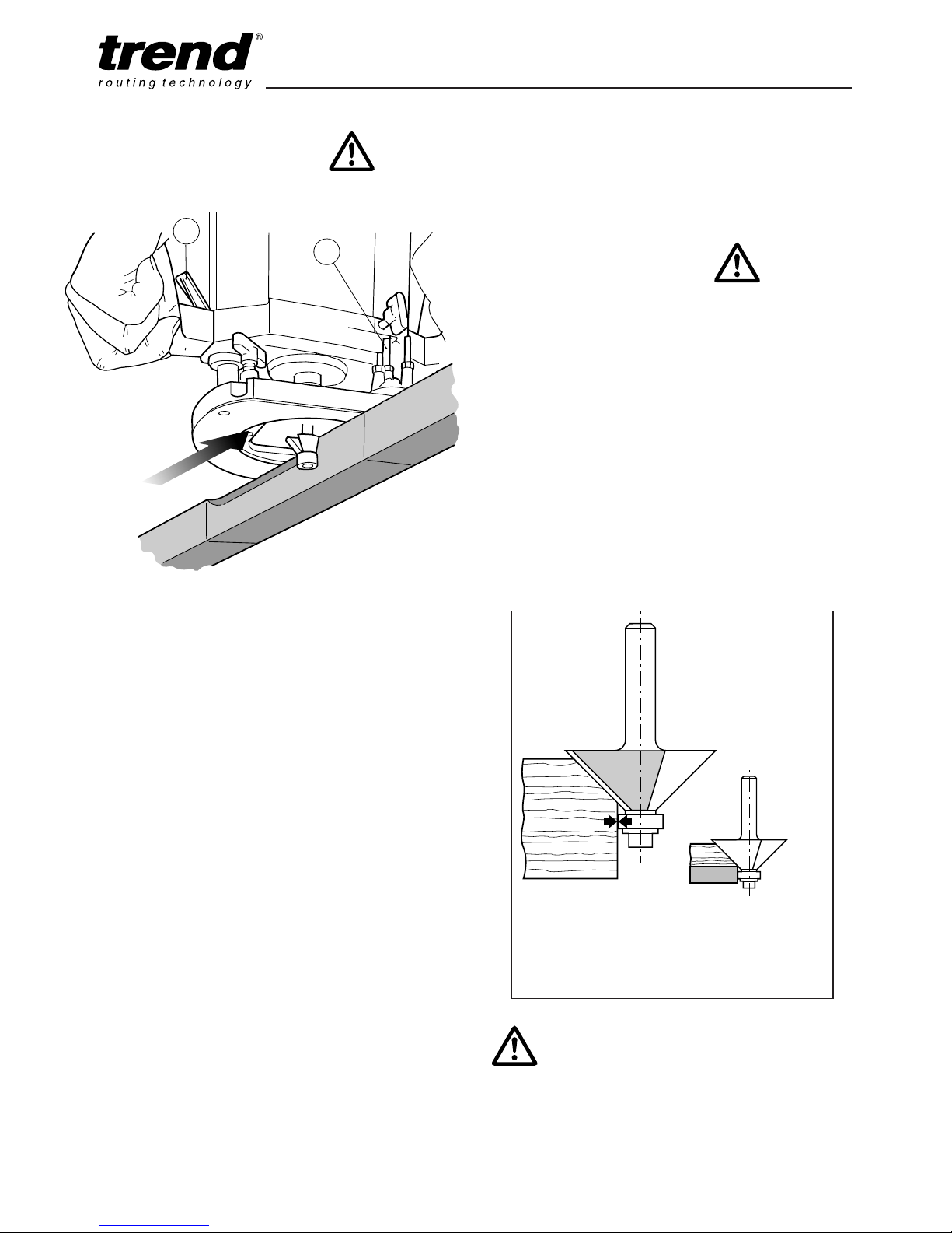
Bearing Guided Cutters
Bearing Guided Cutters
Edge profiling and shaping cutters are available
with a bearing fitted to the end. This enables
shaped or straight workpieces to be routed
without the need for a guiding device such as a
side-fence or batten.
The edge must be free from imperfections as
these will be reflected in the finish of the mould.
Often alternative diameters of bearings are
offered which will change the shape of the
resulting mould.
With certain shapes such as the chamfer cutter
below, increasing the depth of cut will produce a
larger chamfered edge.
n Fit the bearing guided cutter into the router
collet.
n Place router onto the workpiece.
n Set height of cutter using the depth stop (1).
n Switch on the machine.
n After releasing the plunge locking lever (2),
lower the machine slowly as far as the depth
stop.
n With bearing of cutter running along board
edge, mould the edge of the workpiece by
moving the router in the direction shown.
n A continuous motion should be used to
prevent burning of the workpiece. When
possible, take a number of passes at
increased cutter depths. A light final pass will
produce a good finish.
n When complete, retract the carriage by
releasing the plunge locking lever.
n Switch off the router.
2
1
The guide bearing
ensures the cutter
follows the workpiece.
Where the material thickness leaves
insufficient room for the bearing to make
contact, a second piece of material can be
temporarily fixed beneath it for the ball
bearing to follow.
Keep downward pressure with the
inside hand to prevent the router from
tipping.
Page 19
T9
-18-
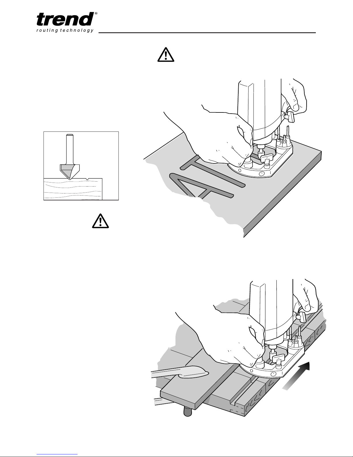
Freehand Routing with the Router
The T9 can also be used for signwriting or
creative freehand work without any form of
guide.
With practice, numbers or name plate designs
can be routed freehand. Draw the design or
motif on the workpiece and then rout the design,
taking shallow passes.
Batten Routing
Where a side-fence cannot be used, it is also
possible to guide the router along a batten
clamped across the workpiece (with an
overhang at both ends).
Guidance from a batten is similar to that
obtained from a side-fence. This method is
appropriate if the edge of the workpiece is not
straight or is not very smooth or simply the
guide rods of the side-fence are too short for
the job.
Use the straight edges of the router base and
calculate the distance required from the edge
of the batten to the cut required. Always
check that the clamps do not obstruct the
path of the router before starting the cut.
Standard technique is used, and
side pressure applied to ensure the
router does not wander from the
batten.
A V groove cutter
is ideal for
engraving designs
at shallow depths.
Page 20
T9
-19-
MAINTENANCE AND CARE
Cleaning
n Keep the machine clean at all times. Some
maintenance products and solvents may
damage the plastic parts, these include
products containing Benzene, Trichloroethyle
Chloride and Ammonia.
n Never use any caustic agents to clean the
plastic parts.
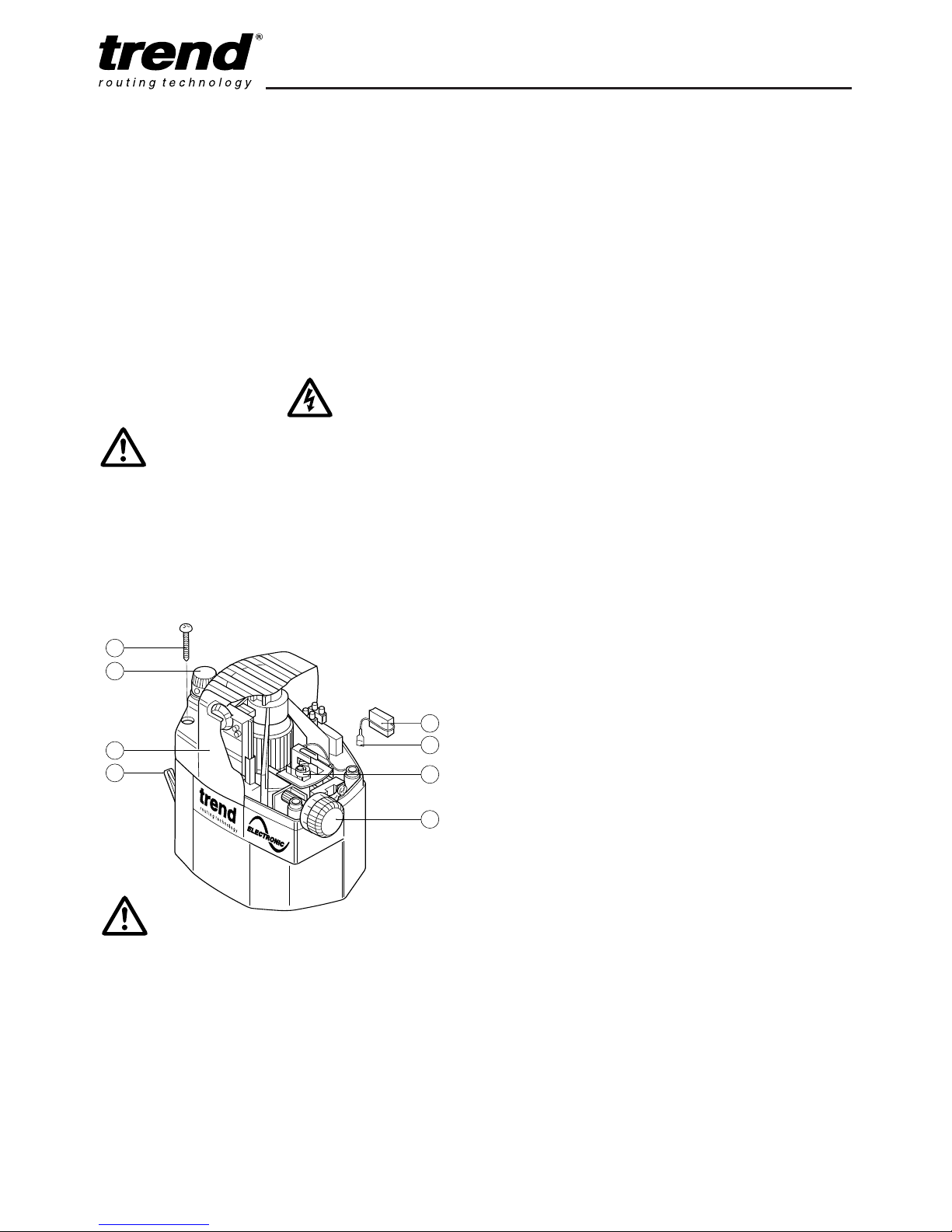
Changing Brushes
n Isolate machine from the power supply.
n Plunge the machine to its lowest point and
lock the plunge lever (1).
n Gently undo the plunge depth knob and rod
assembly (2), and remove.
n Undo the four screws (3), and take off the
cover (4).
n Pull back the spring (5) and unclip the wire
(6).
n Remove the carbon brush (7) and replace it.
n Refit the spring (5) and re-connect the wire
(6).
n Refit the cover (4) ensuring the depth stop
dial (8) is correctly positioned.
n Refit the plunge depth knob and rod assembly
(2) carefully.
n Always use original T9 spare parts.
Lubrication
n The bearings of the machine need no
lubrication, as they are sealed. The two
plunge columns on the routing base should
be slightly oiled from time to time.
n Keep the cooling vents on the motor housing
clean and unobstructed at all times. Blow out
any dust and dirt at regular intervals.
n Visually check the carbon brushes. In the
event of excessive sparking, they may need
changing.
n After about 40 operating hours inspection by
a authorised Trend service agent is
recommended.
RECYCLING
Machine, accessories and packaging should be
sorted for environmentally friendly recycling.
GUARANTEE
The machine carries a manufacturers guarantee
in accordance with the conditions on the
enclosed guarantee card.
For the location of your nearest T
rend Service
7
1
4
2
3
6
8
5
The carbon brushes will need replacing when
they become worn to a certain limit. This will
become evident when the router won’t start up
again after being switched off.
Ensure machine is isolated
from power supply.
It is advisable to have the brushes
replaced by an authorised Trend
service agent. The router will also be
given a thorough inspection.
Page 21

T9
-20-
T9 - SPARE PARTS LIST v4.0 08/2003
No. Qty. Desc. Ref.
1 1 Stator Housing WP-T9/001
2 1 Top Vent Housing WP-T9E/002
3 1 Plunge Depth Stop Knob WP-T9/003
4 1 Speed Control Circuit Board 230V (T9E &
T9/EURO) WP-T9E/004
1 Speed Control Circuit Board 110V (T9EL) WP-T9EL/004
5 1 Cable Guard WP-T9/005
6 1 2 Core Cable With Plug 230V UK (T9) WP-T9/006
1 2 Core Cable With Plug 110V UK (T9L) WP-T9L/006
1 2 Core Cable With Plug 230V Euro (T9/EURO) WP-T9EURO/006
7 1 Carbon Brush 230V (1 pair) WP-T9E/007
1 Carbon Brush 110V (1 pair) WP-T9EL/007
8 2 Brush Holder 230V WP-T9/008
2 Brush Holder 110V WP-T9L/008
9 2 Brush Spring Clip WP-T9/009
10 1 Cable Clip WP-T9/010
11 1 Graduated Ring WP-T9/011
12 1 Depth Stop Adjustment knob WP-T9/012
13 4 Screw Self Tapping 3.9mm x 22mm Pozi WP-T9/013
14 1 Field Coil Complete 230V (T9E & T9/EURO) WP-T9E/014
1 Field Coil Complete 110V (T9EL) WP-T9EL/014
15 2 Machine Screw Pan M5 x 90mm Pozi WP-T9/015
16 1 Deflector WP-T9/016
17 1 Magnet For Speed Control WP-T9E/017
18 1 Magnet Holder Cover WP-T9E/018
19 1 Bearing Cover WP-T9/019
20 1 Top Bearing 9mm x 26mm x 8mm 629ZZ WP-T9/020
21 1 Armature 230V (T9E & T9/EURO) WP-T9E/021
1 Armature 110V (T9EL) WP-T9EL/021
22 1 Fan For Armature WP-T9/022
23 1 Armature/Bearing Ring WP-T9/023
24 1 Bottom Bearing 25mm x 47mm x 12mm 60005Z WP-T9/024
25 1 Bearing Plate WP-T9/025
26 1 Spindle Lock Body WP-T9/026
27 1 Spindle Lock Spring WP-T9/027
28 1 Spindle Lock Button WP-T9/028
29 1 Spindle Lock Stud WP-T9/029
30 1 Collet 6.35mm (T9 & T9L) CLT/T9/635
1 Collet 12.7mm (T9 &T9L) CLT/T9/127
1 Collet 12mm (T9/EURO) CLT/T9/12
31 1 Collet Nut
CL
T/NUT/T9
32 4 Bush For Columns (s/n 100001-101807) WP-T9/032
Page 22

T9
-21-
T9 - SPARE PARTS LIST
v
4.0 08/2003
No. Qty. Desc. Ref.
33 1 Cable Conduit Lower WP-T9/033
34 1 Cable Conduit Upper WP-T9/034
35 1 Switch 230V (T9E & T9/EURO) WP-T9E/035
1 Switch 110V (T9EL) WP-T9EL/035
36 1 Handle Inner Right WP-T9/036
37 1 Handle Outer Right WP-T9/037
38 1 Handle Inner Left WP-T9/038
39 1 Handle Outer Left WP-T9/039
40 1 Plunge Locking Lever WP-T9/040
41 1 Plunge Lever Bolt WP-T9/041
42 1 Depth Stop WP-T9/042
43 2 Plunge Spring (s/n 100001-101807) WP-T9/043
43A 2 Plunge Spring (s/n 101808›) WP-T9/043A
44 2 Nut Hex M4 WP-NUT/04
45 6 Thumb Knob Male M6 x 16mm WP-T9/045
46 1 Parallel Side-fence Complete WP-T9/046
47 1 Parallel Side-fence Casting WP-T9/047
48 1 Side-fence Cheeks (Pair) WP-T9/048
49 1 Guide Rods 10mm x 450mm ROD/10X450
50 - - -
50A 1 Base Casting (s/n 101808›) WP-T9/050A
51 1 Micro Fence Adjuster End Stud WP-T9/051
52 1 Micro Fence Adjuster Barrel WP-T9/052
53 1 Micro Fence Adjuster Knob Stud WP-T9/053
54 1 Micro Fence Adjuster Thumb Knob WP-T9/054
55 - - 56 1 Bearing Ring Circlip WP-T9/056
57 1 Washer 2mm x 10mm x 0.4mm WP-T9/057
58 1 Spacer For Revolving Guide WP-T9/058
59 1 Revolving Guide WP-T9/059
60 1 Ball For Revolving Guide WP-T9/060
61 1 Spring For Revolving Guide WP-T9/061
62 1 Machine Screw Pan Head M5 x 16mm Pozi WP-T9/062
63 3 Nut Hex M5 WP-NUT/05
64 3 Threaded Pin M5 x 16mm WP-T9/064
65 1 Phenolic Base Slider WP-T9/065
66 1 Spanner 22mm A/F SPAN/22
67 1 Lower Bearing Housing (s/n 100001-101807) WP-T9/067
67A 1 Lower Bearing Housing c/w Bushes
(s/n 101808›)
WP-T9/067A
68 1 Magnet Washer WP-T9E/068
69 1 Machine Screw LH M4 x 10mm Slot WP-T9E/069
Page 23

T9
-22-
T9 - SPARE PARTS LIST
v4.0 08/2003
No. Qty. Desc. Ref.
70 1 Conduit Cap WP-T9/070
71 2 Cable Block WP-T9/071
72 1 Block Pad WP-T9/072
73 2 Foam Packing WP-T9/073
74 1 Handle Anti-slip WP-T9/074
75 1 Inner Plate WP-T9/075
76 2 Machine Screw Pan M5 x 12mm Slot WP-SCW/42
77 2 Machine Screw Csk M5 x 8mm Slot WP-SCW/09
78 6 Spring For Thumb Knob WP-T9/078
79 1 Grub Screw M5 x 18mm WP-T9/079
80 4 Machine Screw Pan M5 x 10mm Pozi WP-SCW/44
81 5 Washer 5.4mm x 9.7mm x 1mm WP-T9/081
82 2 Grub Screw M5 x 14mm (s/n 100001-101807) WP-T9/082
83 6 Machine Screw Csk M4 x 8mm Pozi WP-SCW/54
84 2 Machine Screw Pan M5 x 10mm Pozi WP-SCW/44
85 1 Machine Screw Pan M5 x 14mm Pozi WP-SCW/45
86 6 Screw Self Tapping 4.8mm x 19mm Pozi WP-T9/086
87 2 Machine Screw Pan M4 x 14mm Pozi WP-SCW/46
88 3 Screw Self Tapping 4.8mm x 45mm Pozi WP-T9/088
89 2 Machine Screw Socket M8 x 20mm WP-SCW/47
90 1 Line Up Pin 12mm & 1/2” Shank WP-T9/090
91 - - 92 1 Fibre Washer WP-T9/092
93 2 Lead Cable Block to Switch (Blue x 390mm) WP-T9/093
94 2 Lead Switch to Cable Block (Brown x 330mm) WP-T9/094
95 1 Armature Ring WP-T9/095
96 1 Dust Spout WP-T9/096
97 1 Dust Spout Adaptor WP-T9/097
98 1 Dust Spout Insert WP-T9/098
99 2 Lead Brush Holder to Field (Red x 115mm) WP-T9/099
100 1 Screw Self Tapping 4.8mm x 37mm Pozi WP-T9/100
101 2 Machine Screw Pan M5 x 12mm Slot WP-SCW/42
102 2 Washer Split Spring M5 WP-WASH/29
103 0 Base Casting c/w Lower Housing Kit
(s/n 101807›) WP-T9/103
104 1 Plunge Height Adjustment Tube WP-T9/104
105 1 Cable Block and Lead Set 110V (T9EL) WP-T9L/105
106 1 Guide Bush 30mm Diameterl
GB30/A
107 1 Fine height adjuster FHA/002
106 1 Manual MANU/T9
Page 24
T9
-23-
6
5
1
1
12
93
94
1
3
3
79
2
4
9
7
9
9
8
71
1
45
78
82
62
57
58
63
64
59
60
61
32
67
7
8
45
88
32
26
28
27
84
3
0
31
92
43
91
4
3
55
80
81
40
41
86
39
38
89
83
65
75
102
76
90
105
77
49
66
46
107
9
8
99
7
44
10
87
4
2
32
74
88
36
3
5
89
72
70
3
7
86
14
6
9
68
17
15
18
1
9
20
16
98
96
63
101
29
73
34
73
3
3
85
50A
51
54
52
53
82
83
21
22
23
95
56
24
25
47
48
81
80
45
78
106
97
104
8
8
100
103
105
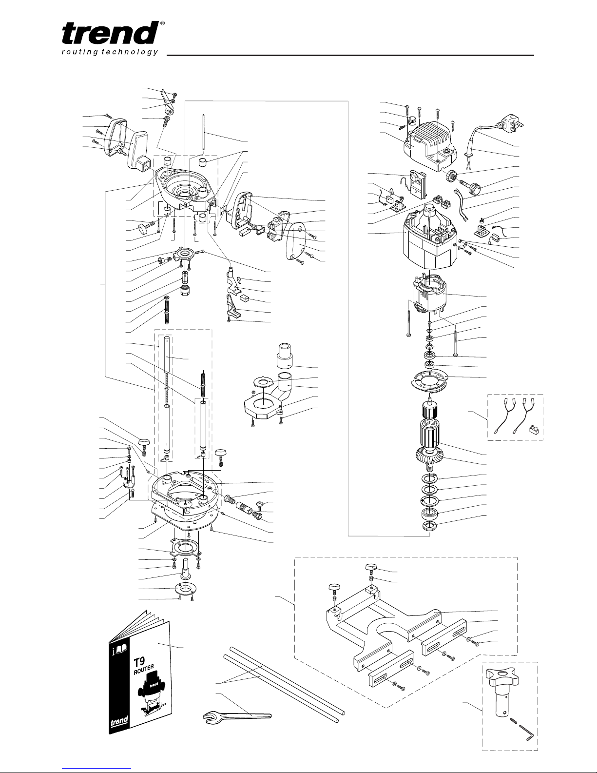
T9 - SPARE PARTS DIAGRAM
v4.0 08/2003
Page 25

T9
-24-
NOTES:
Page 26

MANU/T9 v4.0
© Copyright Trend 2003. No part of this publication may be reproduced, stored or transmitted in any form without prior permission.
Our policy of continuous improvement means that specifications may change without notice. Trend Machinery and Cutting Tools
cannot be held liable for any material rendered unusuable or any form of consequential loss. E&OE
RECYCLABLE
Trend Machinery & Cutting Tools Ltd.
Odhams Trading Estate St Albans Rd
Watford WD24 7TR England
Enquiries:
___________________________________
_
0800 487363
Technical Support:
_______
_
0044 (0) 1923 224681
Fax: ________________0044 (0) 1923 236879
Email:
_______________________
_
Web:
_______________________
_
www.trendmachinery.co.uk
 Loading...