

Page 1

T7
Page 2

Page 3
31
10
11
19
31
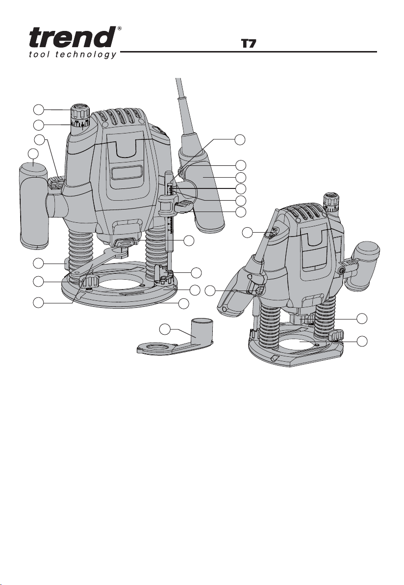
COMPONENT LIST
1
2
3
4
16
6
15
26
5
7
14
17
12
9
8
18
1. Fine-Adjustment Knob For Depth-Of-Cut
2. Scale For Fine Adjustment Of Depth-Of-Cut
3. Clamping Lever
4. Left Handle
5. Scale For Coarse Adjustment Of Depth-Of-Cut
6. Depth Stop
7. Wing Screw For Depth Stop
8. Parallel Guide Fixing Knobs
9. Turret Stop
10. Base Plate
11. Guide Plate
12. Locking Screw For Guide Rod
13. Tightening Nut With Collet
14. Spindle Lock Button
15. Right Handle (With On/Off Switch)
16. Lock-Off Button
*Not all the accessories illustrated or described are included in standard delivery.
17. Thumb-Wheel For Speed Pre-Selection
18. On/Off Switch
19. Span ner
20. Dust Adapter (See C)
21. Parallel Guide (See I)
22. Centre Pin (See M)
23. Markings For Zero-Reset ( See D )
24. Guide Bushing ( See G )
25. Screws And Nuts (See C)
26. Index Mark
27. Guide Rods (See M)
28. Wing Knobs (See M)
29. Router Cutter*
30. Extraction Adapter For Parallel Guide
31. Dust Boots
--
1
13
29
Page 4
A
B
13
14
19
C
20
10
25
E F
D
23
1
2
3
G
11
24
H
--
2
24
Page 5
I J
21
12
10
M
O
K
28
B
A
22
27
C
F
E
L
N
--
3
Page 6

Dear Customer
Thank you for purchasing this Trend product, we hope you enjoy many years of creative and
productive use. Please remember to return your guarantee card within 28 days of purchase.
SYMBOL
To reduce the risk of injur y, user must
read instruction manual
Warning!
Wear ear protection
Wear eye protection
Wear dust mask
--
4
Double insulation
Waste electrical products must not
be disposed of with household waste.
Please recycle where facilities exist.
Check with your local authorities or
retailer for recycling advice.
Page 7

GENERAL POWER TOOL SAFETY WARNINGS
WARNING Read all safety warnings and all instructions.
Failure to follow the warnings and instructions may result in electric shock, fire and/or
serious injury.
Save all warnings and instructions for future reference.
The term “power tool” in the warnings refers to your mains-operated (corded) power tool or
battery-operated (cordless) power tool.
Work area safety
a) Keep work area clean and well lit. Cluttered or dark areas invite accidents.
b) Do not operate power tools in explosive atmospheres, such as in the presence of flammable
liquids, gases or dust. Power tools create sparks which may ignite the dust or fumes.
c) Keep children and bystanders away while operating a power tool. Distractions can cause you
to lose control.
Electrical safety
a) Power tool plugs must match the outlet. Never modify the plug in any way. Do not use any
adapter plugs with earthed (grounded ) power tools. Unmodified plugs and matching outlets
will reduce risk of electric shock.
b) Avoid body contact with earthed or grounded surfaces, such as pipes, radiators, ranges and
refrigerators. There is an increased risk of electric shock if your body is earthed or grounded.
c) Do not expose power tools to rain or wet conditions. Water entering a power tool will increase
the risk of electric shock.
d) Do not abuse the cord. Never use the cord for carrying, pulling or unplugging the power tool.
Keep cord away from heat, oil, sharp edges or moving parts. Damaged or entangled cords
increase the risk of electric shock.
e) When operating a power tool outdoors, use an extension cord suitable for outdoor use. Use of
a cord suitable for outdoor use reduces the risk of electric shock.
f) If operating a power tool in a damp location is unavoidable, use a residual current device
(RCD) protected supply. Use of an RCD reduces the risk of electric shock.
Personal safety
a) Stay alert, watch what you are doing and use common sense when operating a power tool. Do
not use a power tool while you are tired or under the influence of drugs, alcohol or medication.
A moment of inattention while operating power tools may result in serious personal injury.
b) Use personal protective equipment. Always wear eye protection. Protective equipment such
as dust mask, non-skid safety shoes, hard hat, or hearing protection used for appropriate
conditions will reduce personal injuries.
c) Prevent unintentional starting. Ensure the switch is in the off-position before connecting to
power source and/or battery pack, picking up or carrying the tool. Carr ying power tools with
your finger on the switch or energising power tools that have the switch on invites accidents.
d) Remove any adjusting key or wrench before turning the power tool on. A wrench or a key left
attached to a rotating part of the power tool may result in personal injury.
e) Do not overreach. Keep proper footing and balance at all times. This enables better control of
the power tool in unexpected situations.
--
5
Page 8

f) Dress properly. Do not wear loose clothing or jewellery. Keep your hair, clothing and gloves
away from moving parts. Loose clothes, jeweller y or long hair can be caught in moving parts.
g) If devices are provided for the connection of dust extraction and collection facilities, ensure
these are connected and properly used. Use of dust collection can reduce dust-related
hazards.
Power tool use and care
a) Do not force the power tool. Use the correct power tool for your application. The correct power
tool will do the job better and safer at the rate for which it was designed.
b) Do not use the power tool if the switch does not turn it on and off. Any power tool that cannot
be controlled with the switch is dangerous and must be repaired.
c) Disconnect the plug from the power source and/or the battery pack from the power tool
before making any adjustments, changing accessories, or storing power tools. Such
preventive safety measures reduce the risk of star ting the power tool accidentally.
d) Store idle power tools out of the reach of children and do not allow persons unfamiliar with the
power tool or these instructions to operate the power tool. Power tools are dangerous in the
hands of untrained users.
e) Maintain power tools. Check for misalignment or binding of moving parts, breakage of parts
and any other condition that may affect the power tool’s operation. If damaged, have the
power tool repaired before use. Many accidents are caused by poorly maintained power tools.
f) Keep cutting tools sharp and clean. Properly maintained cutting tools with sharp cutting
edges are less likely to bind and are easier to control.
g) Use the power tool, accessories and tool bits etc. in accordance with these instructions,
taking into account the working conditions and the work to be performed. Use of the power
tool for operations different from those intended could result in a hazardous situation.
5) Service
a) Have your power tool serviced by a qualified repair person using only identical replacement
parts. This will ensure that the safety of the power tool is maintained.
ROUTER SAFETY WARNINGS
a) Hold power tool by insulated gripping surfaces, because the cutter may contact its own cord.
Cutting a “live” wire may make exposed metal parts of the power tool “live” and shock the
operator.
b) Use clamps or another practical way to secure and support the workpiece to a stable
platform. Holding the work by your hand or against the body leaves it unstable and may lead to
loss of control.
ADDITIONAL SAFETY INSTRUCTIONS FOR ROUTER
1. Hold tool by insulated gripping surfaces when performing an operation where the cutting tool
may contact hidden wiring. Contact with a “live” wire will make exposed metal parts of the tool
“live” and shock the operator.
2. Use clamps or another practical way to secure and the workpiece to a stable platform. Holding
the work by hand or against your body leaves it unstable and may lead to loss of control.
3. Always wear a dust mask.
4. Wear protective glasses and hearing protection.
--
6
Page 9

5. For long hair, wear hair protection. Work only with closely fitting clothes.
6. If the mains cable is damaged or cut through while working, do not touch the cable. Never use
the machine with a damaged cable.
7. Do not operate the machine in rain or high moisture conditions.
8. Always direct the cable to the rear away from the machine. Take care with the trailing cable
from the router and we recommend that an RCD is user at all times with this machine.
9. Contact with electric lines can lead to fire and electric shock. Damaging a gas line can lead to
explosion. Penetrating a water line causes property damage or may cause an electric shock.
10. When working with machine, always hold it firmly with both hands.
11. Secure the workpiece. A workpice clamped with clamping devices or in a vice is held more
secure than by hand.
12. Before putting into operation, check the routing tool for firm seating.
13. Never route over metal objects such as nails or screws.
14. Keep hands away from rotating router bits.
15. After finishing work, guide the machine back into the upper starting position by actuating the
clamping lever and switch the machine off.
16. Always switch the machine off and wait off and wait until it has come to a standstill before
placing it down.
17. Protect tools from impact and shock.
18. Never allow children to use the machine.
19. Do not use blunt or damaged router bits. Blunt or damaged router bits cause increased
friction, can become jammed and lead to imbalance.
20. The allowable speed of the router bit must be at least as high as the maximum speed listed on
the power tool. Accessories that rotate faster than permitted can be destroyed.
21. Never touch the bit during or immediately after the use. After use the bit is too hot to be
touched by bare hands.
Warning: some dust particles created by power sanding,sawing, grinding , drill and
other construction jobs contain chemicals known to cause cancer, birth defects or
other reproductive harm.
Some examples of these chemicals are:
Lead from lead-based paints.
Crystalline silica from bricks and cement and other masonry products.
Arsenic and chromium from chemically treated timber
Your risk from these exposures varies, depending upon how often you do this type of work. To
reduce your exposure to these chemicals;
Work in a well-ventilated area
Work with approved safety equipment, such as those dust masks that are specially designed to
filler microscopic particles.
--
7
Page 10
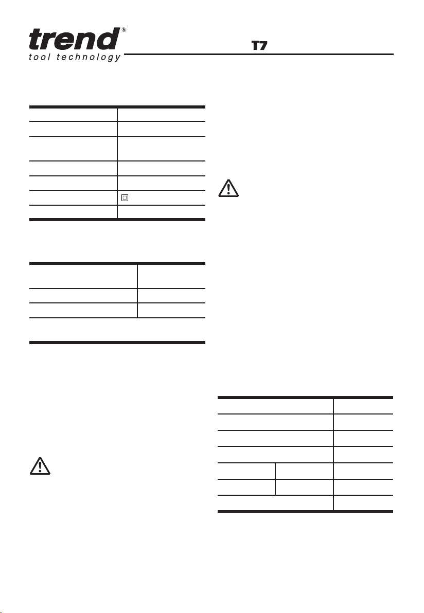
TECHNICAL DATA
Rated Voltage 220-240V~50Hz
Rated Power 2100W
Rated No-load
Speed
Collet size 1/2 & 1/4 inch
Max plunge depth 50mm
Double insulation
Machine weight 4.3Kg
11500~28000/min
NOISE INFORMATION
A weighted sound
pressure
A weighted sound power LwA =101dB(A)
LpA&KwA 3.0dB(A)
Wear Ear Protection when sound pressure is
over 80dB (A)
Vibration Information
Vibration total values (triax vector sum)
determined according to EN 60745:
Vibration emission value: ah = 4.90 m /s2
Uncertainty K = 1.5 m/s²
The declared vibration total value may be used
for comparing one tool with another, and may
also be used in a preliminary assessment of
exposure.
WARNING: The vibration emission
value during actual use of the power tool
can differ from the declared value depending on
the ways in which the tool is used dependant on
the following examples and other variations on
how the tool is used:
How the tool is used and the materials being cut
or drilled.
The tool being in good condition and well
maintained
Using the correct accessory for the tool and
LpA =90 dB(A)
ensuring it is sharp and in good condition.
The tightness of the grip on the handles and if
any anti vibration accessories are used.
And the tool is being used as intended by its
design and these instructions.
This tool may cause hand-arm vibration
syndrome if its use is not adequately
managed
WARNING: To be accurate, an
estimation of exposure level in the actual
conditions of use should also take account
of all par ts of the operating cycle such as the
times when the tool is switched off and when
it is running idle but not actually doing the job.
This may significantly reduce the exposure
level over the total working period.
Helping to minimise your vibration exposure
risk.
ALWAYS use sharp chisels, drills and blades
Maintain this tool in accordance with these
instructions and keep well lubricated (where
appropriate)
If the tool is to be used regularly then invest in
anti vibration accessories.
Plan your work schedule to spread any high
vibration tool use across a number of days.
ACCESSORIES
Centre pin
Parallel guide
Template Guide(30mm)
Spanner
Collet 1/4 inch
1/2 inch
Dust extraction tube
We recommend that you purchase your
accessories from the same store that sold you the
tool. Refer to the accessory packaging for fur ther
details. Store personnel can assist you and offer
advice.
1
1
1
1
1
1
1
--
8
Page 11

OPERATING
INSTRUCTIONS
WARNING: Do not tighten the
tightening nut of the collet without a
router bit inserted.
NOTE: Before using the tool, read the
instruction book carefully.
Intended Use
The machine is intended for routing grooves,
edges, profiles and elongated holes as well
as for copy routing in wood, plastic and light
building materials, while resting firmly on the
workpiece.
1.INSERT THE ROUTER CUTTER
Router Cutter Selection
Depending on processing and application,
router Cutter are available in many dif ferent
designs and qualities :
Router cutter made of high-speed steel
(HSS) is suitable for the machining of soft
materials, e. g. sof twood and plastic.
Carbide tipped router Cutter (HM) is
particularly suitable for hard and abrasive
materials, e. g. hard wood and aluminum.
WARNING: Use only routing tools with
an allowable speed matching at least
the highest no load speed of the machine.
The shank diameter of the router cutter
must correspond with the rated diameter of
the collet.
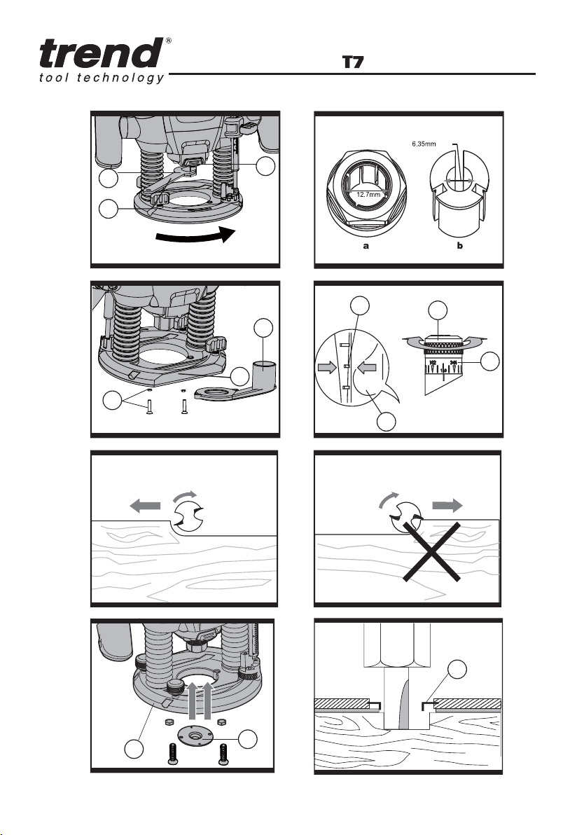
Inserting Router Cutter (See A)
Before any work on the machine
itself, disconnect the mains plug. It is
recommended to wear protective gloves
when inserting or replacing router cutter.
Press spindle lock button (14) and keep
depressed. If required, turn the spindle by hand
until the lock engages.
Press the spindle lock button only when at a
standstill.
Insert router Cutter. The shank of the router
Cutter must be inserted at least 20 mm (shank
length).
Tighten the tightening nut (13) with the spanner
(19) (size 22 mm). Release the spindle lock
button.
HOW TO FIT THE 6.35 MM COLLET (SEE B)
This router is supplied with a 6.35mm collet as
an accessory.
To fit the 6.35 mm collet (b) simply slide it into
the 12.7mm collet (a) fitted to the collet nut.
The 6.35 mm collet has a flange coller to ensure
insertion to correct depth.
NOTE: 1. Do not attempt to remove the
12.7mm collet from the collet nut.
2. Always wear safety gloves when changing
the router cutter.
2. MOUNTING THE EXTRACTION ADAPTER
(See C)
To connect the vacuum cleaner via a suction
hose, you must fasten dust adapter (20) to base
plate (10) with both screws and nuts (25).
WARNING: When mounting the
extraction adapter, ensure correct
mounting position!
For dust extraction, the vacuum hose can
be connected directly to the extraction
adapter.
Clean the dust adapter (20) regularly to
ensure optimum dust extraction at all
times.
The vacuum cleaner must be suitable for
the material to be worked.
When vacuuming dry dust that is especially
detrimental to health or carcinogenic, use a
special vacuum cleaner.
3.ON AND OFF SWITCH
a)LOCK-OFF SWITCH
For star ting operation of the machine, actuate
the lock-off button (16) first, then press and hold
the On/Off switch (18) after wards. To switch off
the machine, release the On/Off switch (18).
For safety reasons the On/Off switch of the
machine cannot be locked; it must remain
pressed during the entire operation.
--
9
Page 12

Speed Pre-selection
The required speed can be pre-selected with
the thumb-wheel (17) (also whilst running).
1 – 2 = low speed
3 – 4 = medium speed
5 – 6 = high speed
The required speed is dependent on the
material and can be determined by practical
testing.
After longer periods of working at low speed,
allow the machine to cool down by running it
for approx. 3 minutes at maximum speed with
no load.
Speed Table
Material Router bit-Ø Speedstages
Hardwood 4 –10 mm 5– 6
(Beech) 12–20 mm 3–4
22 – 40 mm 1–2
Softwood 4 – 10 mm 5– 6
(Pine) 12 – 20 mm 3–6
22 – 40 mm 1–3
Particle board
12 – 20 mm 2–4
22 – 40 mm 1–3
Plastic 4 – 15 mm 2–3
16 – 40 mm 1–2
Aluminium 4 – 15 mm 1–2
16 – 40 mm 1
The values shown in the chart are standard
values. The necessary speed depends on the
material and the operating conditions, and can
be determined by practical testing.
Constant Electronic Control and Soft Start
Constant electronic control maintains the
speed constant at no-load and under most
working conditions. Soft start delays the
increase in motor speed to reduce the motor
“kick” or torque effect to improve operator
comfort and safety.
4. SETTING THE DEPTH-OF-CUT
Depending on the cutting operation, the depthof cut can be preset in several steps.
WARNING:
The adjustment of the depth-of-cut may
only be carried out when the router is switched
off.
4 – 10 mm 3–6
--
10
Coarse Adjustment of the Depth-of-cut
(See D)
Place the router on the work-piece to be
machined.
Set the fine adjustment for depth-of-cut in the
centre position with fine-adjustment knob (1);
to do this, turn the fine-adjustment knob until
the markings (23) on the backside of the router
are in alignment, as shown. Afterwards turn
scale ( 2) to “0” (See D). Set Turret Stop (9 ) to
the lowest position; the Turret Stop snaps-in
noticeably.
Loosen locking screw (7), so that depth stop (6 )
can be moved freely.
Release the clamping lever (3) by turning
in clockwise direction and slowly lower the
router until the router bit touches the surface
of the workpiece. Lock the router in position
by turning the clamping lever in anti-clockwise
direction.
Press depth stop downwards until it touches
the Turret Stop ( 9). Adjust the depth stop (6)
to the required routing depth and tighten the
wing screw (7). Release the clamping lever and
guide the router back up again.
The coarse adjustment of the depth-of-cut
should be checked by a trial cut and corrected,
if necessary.
Fine Adjustment of the Depth-of-cut
After a trial cut, fine adjustment can be carried
out by turning the fine adjustment knob (1
scale mark = 0.1 mm/1 rotation = 2.0 mm).
The maximum adjustment is approx. +/– 8 mm.
Example: Slide router upwards again and
measure the depth-of-cut (set value = 10.0 mm;
actual value = 9.8 mm ).
Lift up router and underlay guide plate (11) in
such a manner that the router can plunge freely
without the router bit touching the work-piece.
Lower the router again until the depth stop
touches the step buffer (9).
Afterwards set scale ( 2) to “0”.
Loosen wing screw.
With the fine adjustment (1), advance the
depth-of-cut in clockwise direction by 0.2 mm/
Page 13

2 scale marks (= difference between required
value and actual value).
Retighten wing screw again.
Slide router upward again and check depth-ofcut by carrying out another trial cut.
After setting the depth-of-cut, the position of
the index mark (26), on the depth stop should
not be changed anymore so that the currently
adjusted setting can always be read off the
scale
5. USAGE OF THE TURRET STOP
a) Dividing the cutting procedure in several
steps
For deep cuts, it is recommended to carry out
several cuts, each with less material removal.
By using the Turret Stop, the cutting process
can be divided into several steps.
Set the required depth-of-cut with the lowest
step of the Turret Stop. Afterwards, the higher
steps can be used for the last two cuts.
b) Pre-adjustment of varying depth-of-cuts
If several different depth-of-cuts are required
for the machining of a work-piece, these can
also be preset by using the Turret Stop.
6. DIRECTION OF FEED (See E, F)
The feed motion of the router must always be
carried out against the rotation direction of the
router Cutter (up-grinding).
When milling in the direction with the rotation of
the router cutter (down cutting), the router can
break loose, preventing control by the user.
7. ROUTING PROCESS
Adjust the depth-of-cut as previously
described.
Place the router on the work-piece.
Release the clamping lever by turning in
clockwise direction and slowly lower the router
until the depth stop runs against the Turret
Stop. Lock the router in position by turning
the clamping lever in anti-clockwise direction,
then switch on. Carry out the cutting procedure
with uniform feed. After finishing the cutting
process, slide the router upwards again and
switch off.
8. ROUTING WITH GUIDE BUSHING (See G).
The guide bushing ( 24) enables template and
pattern routing on work-pieces.
Place the guide bushing over the hole in
the centre of the base plate, and align the
two through holes in the bottom of the base
plate with the countersunk holes in the guide
bushing. Fasten the guide bushing with the
nuts and screws provided.(See G).
9. ROUTING PROCESS (See H)
WARNING: Choose a router Cutter
with a smaller diameter than the inner
diameter of the guide bushing.
Set the router with guide bushing against the
template. Release the clamping lever by turning
in clockwise direction and slowly lower the
router toward the work-piece until the adjusted
depth-of-cut is reached.
Guide router with projecting guide bushing
along the template, applying light sideward
pressure.
Note: The template must have a minimum
thickness of 8 mm, due to the projecting height
of the guide bushing.
10. SHAPING OR MOULDING
APPLICATIONS
For shaping or molding applications without
the use of a parallel guide, the router must be
equipped with a pilot or a ball bearing.
Lead the router sideward to the workpiece
and allow router bit to engage until the pilot or
the ball bearing of the router reach the corner
of the workpiece being machined. Guide the
router alongside the workpiece corner using
both hands, ensuring proper seating of the
base plate. Too much pressure can damage the
edge of the workpiece.
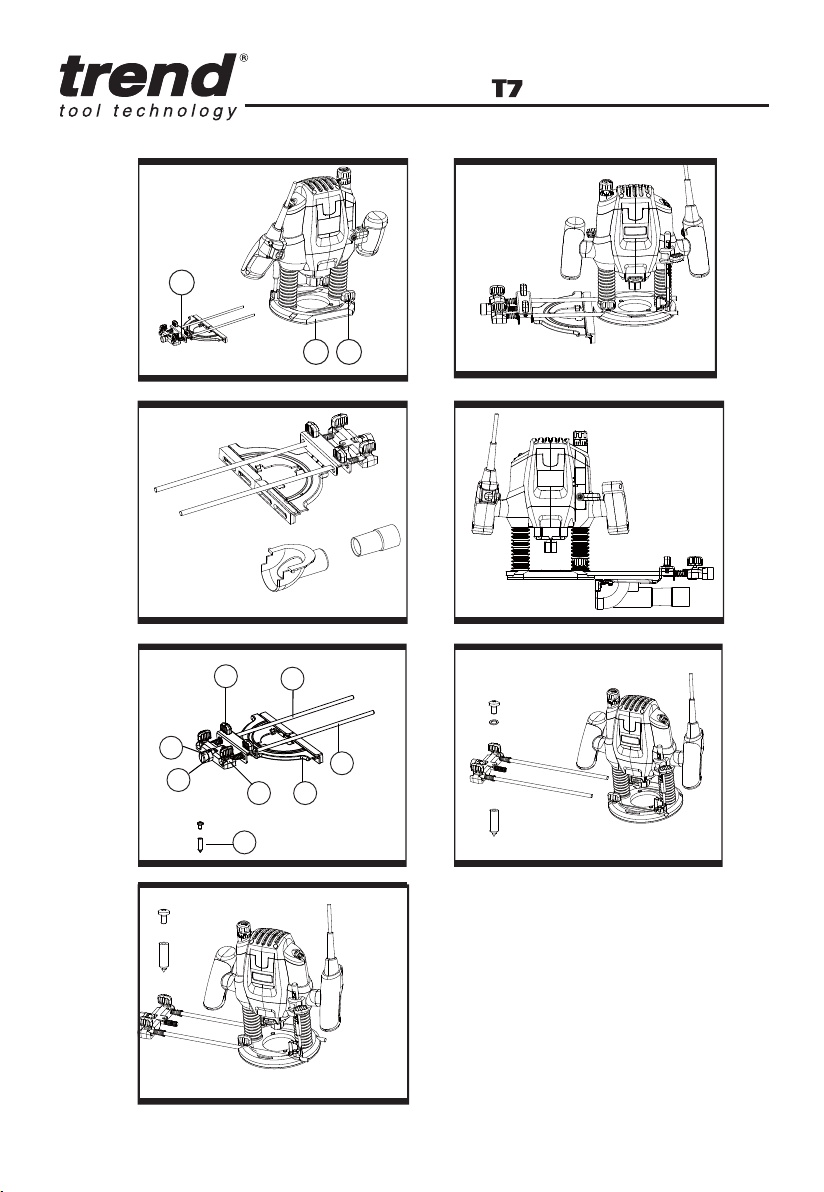
11. ROUTING WITH PARALLEL GUIDE
(Accessory – See I, J)
Slide the parallel guide (21) with the guide rods
(27) into the base plate (10) and tighten at the
required measure with the wing bolts (12).
Guide the machine with uniform feed and
--
11
Page 14

sideward pressure on the parallel guide ( 21)
along the edge of the workpiece.
12. USING EXTRACTION ADAPTER FOR
PARALLEL GUIDE (See K, L)
When the machine routing on an vertical
surface, the dust/chip extraction should take
place via the special extraction adapter for the
parallel guide (30).
To mount the extraction adapter for the parallel
guide, first insert the tab (a) into place, then
engage the front two tabs into place. And then
mount the parallel guide with the extraction
adapter onto the router.
• Adjust the position of the rods and router as
necessary to achieve the desired radius of
the circle or arc, then securely tighten wing
knobs.
14. ROUTER CUTTER
Before proceeding, carry out test cut on waste
timber. Only use cutters with a shank that
matches the collet used.
HSS (High Speed Steel) - for softwood use.
TCT (Tungsten Carbide Tipped ) - for use on
hardwood, chipboard, plastics or aluminium.
The most commonly used bits are listed below.
13. ROUTING CIRCULAR ARC PROFILES
(See M, N, O)
To reassemble the router guide for use as a circle
guide (arc guide), follow below steps:
• Loosen rear wing knobs (28) and fine
adjustment knob (A), spacer, and indicator
(B), remove these parts from guide rods (C).
• Loosen front knobs and guide base ( E),
remove from the guide rods.
• Remove springs (D) from guide rods.
• Reinstall fine adjustment guide ( F) onto
guide rods rotate 180 degrees from normal
position so that circle guide hole faces away
from the router.
• Insert the guide rods (C) into router base.
For maximum stability, make sure each rod
goes through both holes and protrudes
out the other side of the router base. At a
maximum, the rods must be inserted far
enough into the router base that they are
supported from below base.
• Securely fasten the router to the rods by
tightening the locking screws (12). The
largest circles and arcs can be made when
the guide rods enter the side of the router
where the locking screws (12) are located.
• Mark the workpiece at the centre of the
desired circle.
• Loosen the screw of centre pin (22 ), and fit
into the centre hole of the adjustment guide
(F), then fasten the screw to use.
• Place the centre pin against the mark of
desired circle on the workpiece.
MAINTENANCE
Please use only Trend origional spare parts
and accessories
Remove the plug from the socket before
carrying out any adjustment, servicing or
maintenance.
Your power tool requires no additional
lubrication or maintenance.
There are no user serviceable parts in your
power tool. Never use water or chemical
cleaners to clean your power tool. Wipe clean
with a dry cloth. Always store your power tool
in a dry place. Keep the motor ventilation slots
clean. Keep all working controls free of dust.
Occasionally you may see sparks through the
ventilation slots. This is normal and will not
damage your power tool.
If the supply cord is damaged, it must be
replaced by the manufacturer, its service agent
or similarly qualified persons in order to avoid
a hazard.
--
12
Page 15

ENVIRONMENTAL
PROTECTION
Recycle raw materials instead of disposing
as waste.
Accessories and packaging should be sor ted
for environmental-friendly recycling.
Separate collection.
This product must not be dispose of with
normal household waste.
Household user
Local regulations may provide for separate
collection of electric products from the
household, at municipal waste sites or by
retailer when you purchase a new product.
Please call Trend Customer Services for
advice as to how to dispose of unwanted Trend
electrical products in an environmentally safe
way or visit www.trend-uk.com
Business Users
Please call Trend Customer Services for
dispose of unwanted Trend electrical products.
GUARANTEE
The unit carries a manufacturer guarantee
in accordance with the conditions on the
enclosed guarantee card.
PLUG REPLACEMENT
(ONLY FOR REWIRABLE
PLUG OF UK & IRELAND)
If you need to replace the fitted plug then follow
the instructions below.
IMPORTANT
The wires in the mains lead are colored in
accordance with the following code:
BLUE =NEUTRAL
Brown = Live
As the colors of the wires in the mains lead of
this appliance may not correspond with the
colored markings identifying the terminals
in your plug, proceed as follows. The wire
which is colored blue must be connected to
the terminal which is marked with N. The wire
which is colored brown must be connected to
the terminal which is marked with L.
WARNING:Never connect live or neutral wires
to the earth terminal of the plug. Only fit an
approved 13ABS1363/A plug and the correct
rated fuse.
NOTE: If a moulded plug is fitted and has to
be removed take great care in disposing of the
plug and severed cable, it must be destroyed to
prevent engaging into a socket.
For the location of your nearest Trend Service
Agent, please call Trend Customer Services or
see our stockiest locator at www.trend-uk.com.
--
IB
Page 16

Trend Machinery & Cutting Tools Ltd,
Unit 6 Odhams Trading Estate,
St. Albans Road, Watford,
Herts, WD24 7TR
MANU/T7 V1.0
©Copyright Trend 2019. No part of this publication may be reproduced, stored or transmitted in any form without prior permission.
Our policy of continuous improvement means that specifications may change without notice. Trend Routing Technologies Inc.
cannot be held liable for any material rendered unusable or any form of consequential loss. E&OE
RECYCLABLE
®
All trademarks acknowledged.
United Kingdom
 Loading...