

Page 1
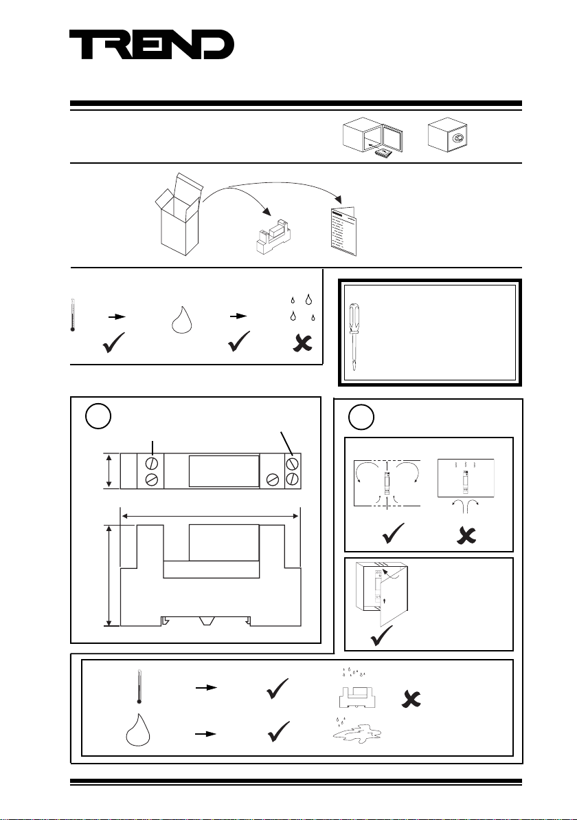
Single Relay Module (Voltage)
A2coil A1
NO 14
NC
12
11
CO
Important: Retain these instructions
1 UNPACKING
2 STORING
-40 °C
(-40 °F)
3 INSTALLATION
+70 °C
(+158 °F)
H O
2
0 %RH
95 %RH
Installation Instructions
SRMV
SRMV Installation Instruction
91-2853
It is recommended that the installation
should comply with the HSE
Memorandum of Guidance on
Electricity at Work Regulations 1989.
For USA install equipment in
accordance with the National
Electric Code.
1
(0.61”)
15.5 mm
Dimensions
coil terminals
A2 coil A1
relay contact
terminals
NO
14
Requirements
2
11
C O
N C
12
a
CO
NC
12
CO
NC
12
11
NO14
A2coil A1
11
NO14
A2coil A1
75.5 mm (2.97”)
SRMV/USA: the unit
is UL rated as
42 mm (1.65”)
‘UL916 listed open
energy management
equipment
accessory’.
c
-25 °C
(-13 °F)
0 %RH 90 %RH
H O
2
SRMV Installation Instructions 91-2853 Issue 3/C 22/11/06
+85 °C
(+185 °F)
Protection: IP20
(NEMA1)
1
Page 2
SRMV Installation Instructions
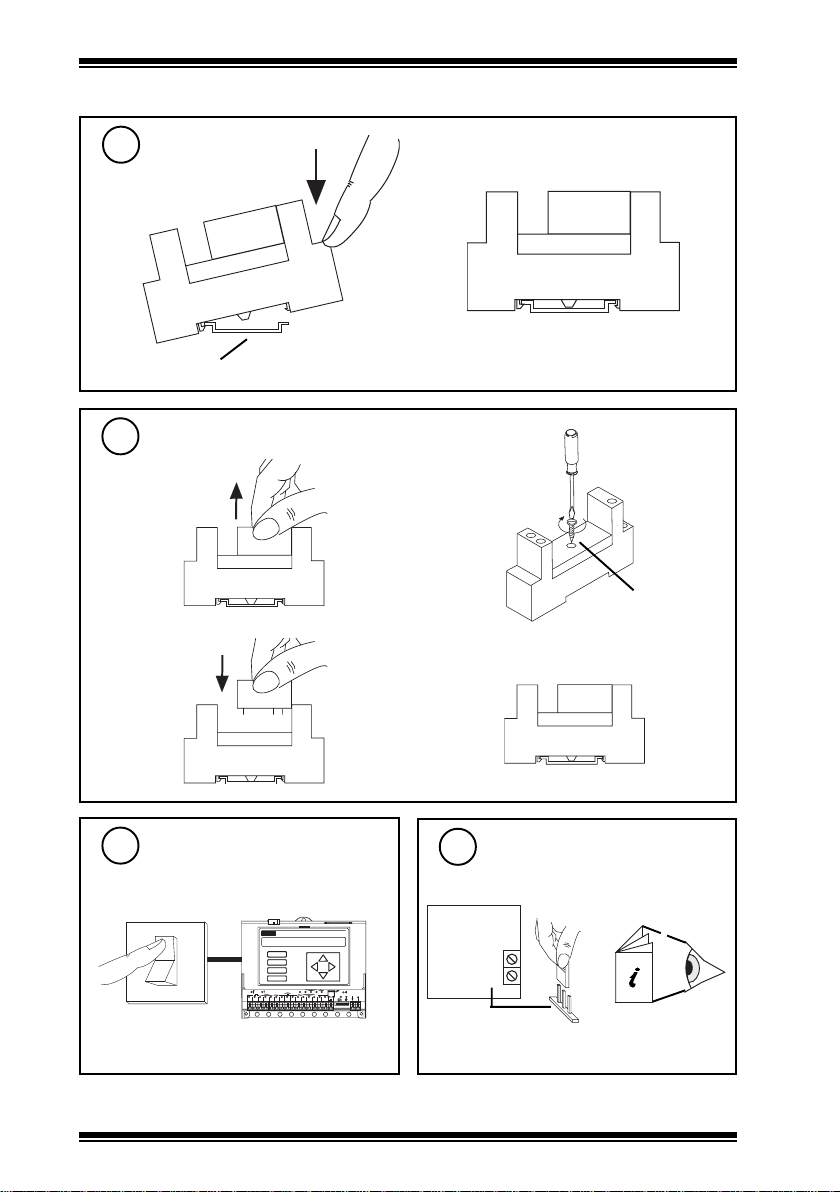
3 INSTALLATION (Continued)
Fit to DIN rail
3
a
Standard top hat DIN rail (DIN 46277-3, EN50022, BS5584:1978)
To Mount on Flat Surface
4
a
c
b
b
Ø 3 mm
(0.118”)
d
5
Switch off IQ
Ensure IQ Output channel
6
is Analogue set to Voltage
IQ
O
I
A
B
C
D
1
6 7 8
2 3 4 5
2
D P
O K
1 7
2 0
1 8
1 6
1 9
LA N
TX R X
V
24 V
1 1
9 1 0
1 2
1 3
1 5
1 4
12 34 56 7 89 10
IQ
SIG
0 V
V
IQ Controller
Installation Instructions
SRMV Installation Instructions 91-2853 Issue 3/C 22/11/06
Page 3

Installation Instructions SRMV
O
I
3 INSTALLATION (Continued)
Wire module to controller
7
Terminal size 2 x 2.5 mm2 (11 AWG) wires - Cu only
I = 17.5 mA
IQ
SIG
0 V
A2
A1
SRMV
Relay
coil
A2 coil A1
polarity independent
Ensure HVAC Equipment Power Supply is Switched off
8
Power Supply
SRMV
HVAC
Equipment
Power
Connect Relay to HVAC Equipment
9
250 Vac @ 8A (resistive), 5A (inductive,
cos ø>=0.4)
20 Vdc @ 8A (resistive)
24 Vdc @ 2A (inductive, T<=30 ms)
SRMV
A2 coil A1
11
C O
NO
N C
14
12
NO
C
11
14
12
Power
Supply
NO
14
HVAC
Equipment
11
C O
N C
12
For SRMV/USA the UL rating applies to loads
of up to 30 V.
Terminal size 2 x 2.5 mm
Cu only
WARNING: The wires may be connected to
hazardous voltages. Disconnect
power before attempting any
wiring.
SRMV Installation Instructions 91-2853 Issue 3/C 22/11/06
2
(11 AWG) wires -
NC
use either normally open or
normally closed contact
Arc suppression
recommended
Relay Output Arc
Suppression Installation
Instructions TG200208
3
Page 4

SRMV Installation Instructions
A2coil A1
NO 14
NC
12
11
CO
3 INSTALLATION (Continued)
10
Close panel
SRMV/USA. The unit is UL rated as ‘UL916
listed open energy management equipment
accessory.
12
Switch on HVAC Equipment Power Supply
O
I
SRMV
13
Check Relay operation
IQ
DP
A
B
C
1
2345
D
678
9101112
16
OK
17
20
18
19
LAN
TX RX
V
24V
13
15
14
12345678910
Power Supply
SRMV
A2 coil A1
11
NO
14
Switch on IQ
O
I
HVAC
Equipment
Power
11
CO
N C
12
Equipment
‘click’
HVAC
IQ
D P
A
B
C
D
1
6 7 8
2 3 4 5
O K
1 7
2 0
1 8
1 6
1 9
LA N
TX R X
V
24 V
1 1
9 1 0
1 2
1 3
1 5
1 4
12 34 56 7 89 10
4 DISPOSAL
WEEE Directive :
At the end of their useful life the packaging,
and product, should be disposed of by a
Do not dispose of with normal household waste.
Do not burn.
Manufactured for and on behalf of the Environmental and Combustion Controls Division of Honeywell Technologies Sàrl, Ecublens, Route
du Bois 37,Switzerland by its Authorized Representative, Trend Control Systems Limited.
Trend Control Systems Limited reserves the right to revise this publication from time to time and make changes to the content hereof
without obligation to notify any person of such revisions or changes.
Trend Control Systems Limited
P.O. Box 34, Horsham, West Sussex, RH12 2YF, UK. Tel:+44 (0)1403 21888 Fax:+44 (0)1403 241608 www.trend-controls.com
Trend Control Systems USA
6670 185th Avenue NE, Redmond, Washington 98052, USA. Tel: (425)897-3900, Fax: (425)869-8445 www.trend-controls.com
4
suitable recycling centre.
SRMV Installation Instructions 91-2853 Issue 3/C 22/11/06
 Loading...