

Page 1
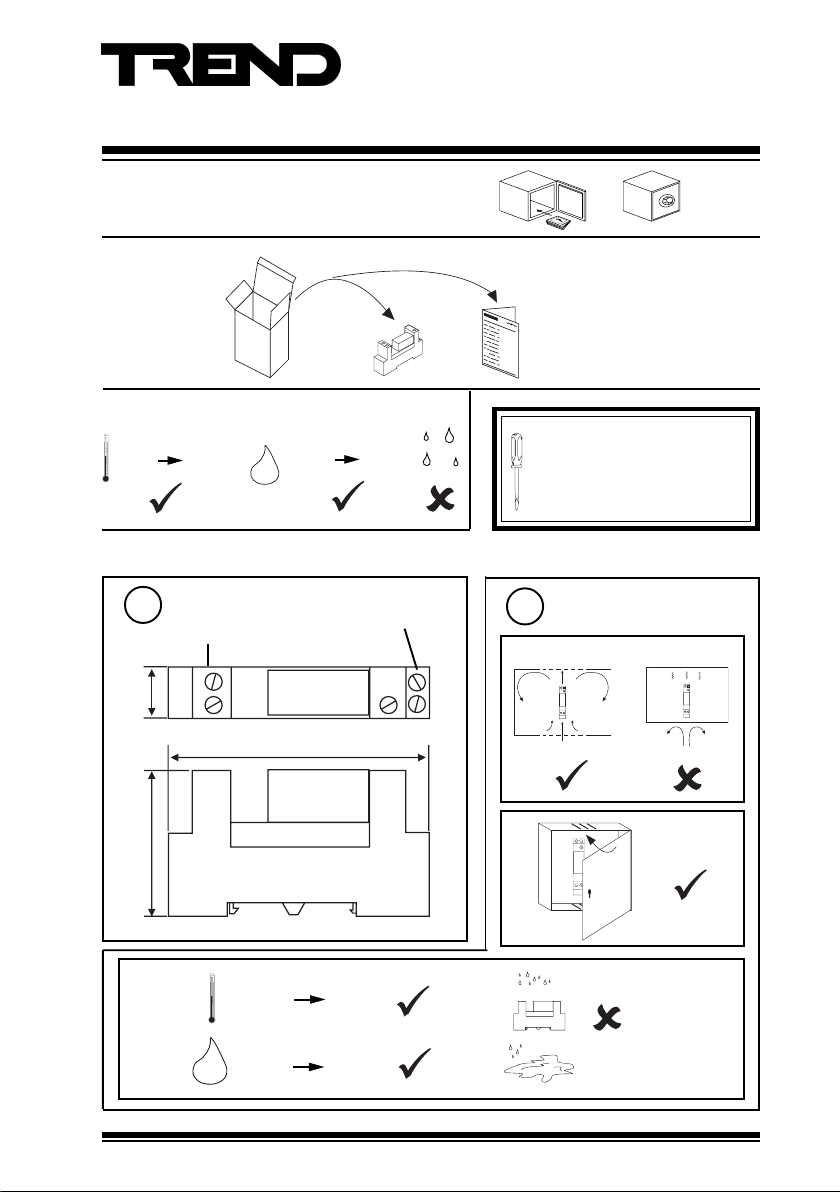
Single Relay Module (24 Vac)
A2coil A1
NO14
NC
12
11
CO
A2coil A1
NO 14
NC
12
11
CO
Important: Retain these instructions
UNPACKING
STORING
-40 °C
(-40 °F)
INSTALLATION
+70 °C
(+158 °F)
H O
2
0 %RH
95 %RH
Installation Instructions
SRMAC
SRMAC Installation Instruction
TG101985
It is recommended that the
installation should comply with the
HSE Memorandum of Guidance
on Electricity at Work Regulations
1989.
1
coil terminals
(0.61”)
15.5 mm
Dimensions
A2 coil A1
relay contact
terminals
NO
14
11
C O
N C
12
2
a
CO
NC
12
11
NO14
A2coil A1
Requirements
75.5 mm (2.97”)
42 mm (1.65”)
c
25 °C
(-13 °F)
0 %RH 90 %RH
H O
SRMAC Single Relay Module (24 Vac) Installation Instructions TG101985 Issue 2/B 21/04/05
2
+85 °C
(+185 °F)
Protection: IP20
1
Page 2
SRMAC Installation Instructions
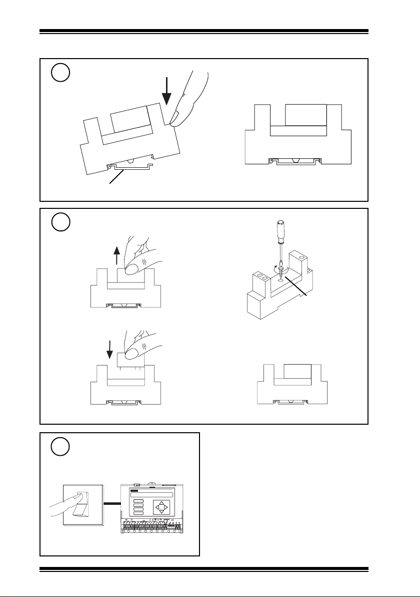
INSTALLATION (continued)
Fit to DIN rail
3
a
b
Standard top hat DIN rail (DIN 46277-3, EN50022, BS5584:1978)
To Mount on Flat Surface
4
a
c
b
d
Ø 3 mm
(0.118”)
Switch off IQ
5
IQ
O
I
2
A
B
C
D
1
6 7 8
2 3 4 5
SRMAC Single Relay Module (24 Vac) Installation Instructions TG101985 Issue 2/B 21/04/05
D P
O K
2 0
1 7
1 8
1 6
1 9
LA N
TX R X
V
24 V
1 1
9 1 0
1 2
1 3
1 5
1 4
12 34 56 78 91 0
Page 3

Installation Instructions SRMAC
O
I
INSTALLATION(continued)
Wire module to controller
6
Terminal size 2 x 2.5 mm2 (11 AWG) wires
triac output
IQ
24 V
OUT
Ensure Plant Supply is Switched off
7
I = 31.6 mA
SRMAC
A2
Relay
coil
A1
polarity independent
SRMAC Plant
Supply
A2 coil A1
Supply
11
C O
NO
N C
14
12
Connect Relay to Plant Item
8
250 Vac @ 10 A (resistive), 5 A
(inductive, cos ø>=0.4)
20 Vdc @ 8 A (resistive)
24 Vdc @ 2 A (inductive, T<=30 ms)
SRMAC
A2 coil A1
11
C O
NO
N C
14
C
12
Terminal size 2 x 2.5 mm2 (11 AWG) wires
WARNING: The wires may be connected
to hazardous voltages.
Disconnect power before
attempting any wiring.
SRMAC Single Relay Module (24 Vac) Installation Instructions TG101985 Issue 2/B 21/04/05
Supply
11
14
NO
12
NC
use either normally open or
normally closed contact
Arc suppression
recommended
Relay Output Arc
Suppression Installation
Instructions TG200208
Plant
item
3
Page 4

SRMAC Installation Instructions
INSTALLATION (continued)
Close panel
9
CO
NC
12
11
NO 14
A2coil A1
11
Switch on Plant supply
Supply
O
I
SRMAC Plant
12
Check Relay operation
IQ
A
B
C
D
17
20
18
16
19
V
1
2345
678
9101112
24V
13
15
14
12345678910
10
Switch on IQ
IQ
O
I
A
B
C
D
1
6 7 8
2 3 4 5
D P
O K
1 7
2 0
1 8
1 6
1 9
LA N
TX R X
V
24 V
1 1
9 1 0
1 2
1 3
1 5
1 4
12 34 56 78 91 0
Supply
DP
SRMAC
A2 coil A1
OK
LAN
TX RX
11
CO
NO
N C
14
12
‘click’
Plant
DISPOSAL
WEEE Directive :
At the end of their useful life the packaging
and product should be disposed of via a
Do not dispose of with normal household waste.
Do not burn.
Trend Control Systems Ltd reserves the right to revise this publication from time to time and make changes to the content hereof without
obligation to notify any person of such revisions or changes.
Registered office, 24 Queens Road Weybridge Surrey KT13 9UX Registered in England No 1664519
4
suitable recycling centre.
P.O. Box 34, Horsham, West Sussex, RH12 2YF United Kingdom Website www.trend-controls.com
Fax (UK) +44 (0)1403 241608Fax (International) +44 (0)1403 210982Telephone +44 (0)1403 21888
SRMAC Single Relay Module (24 Vac) Installation Instructions TG101985 Issue 2/B 21/04/05
 Loading...