

Page 1
Surface Mount Touch Screen Display
Important: Retain these instructions
Installation Instructions - Sheet 1
IQView../SM
CONTENTS
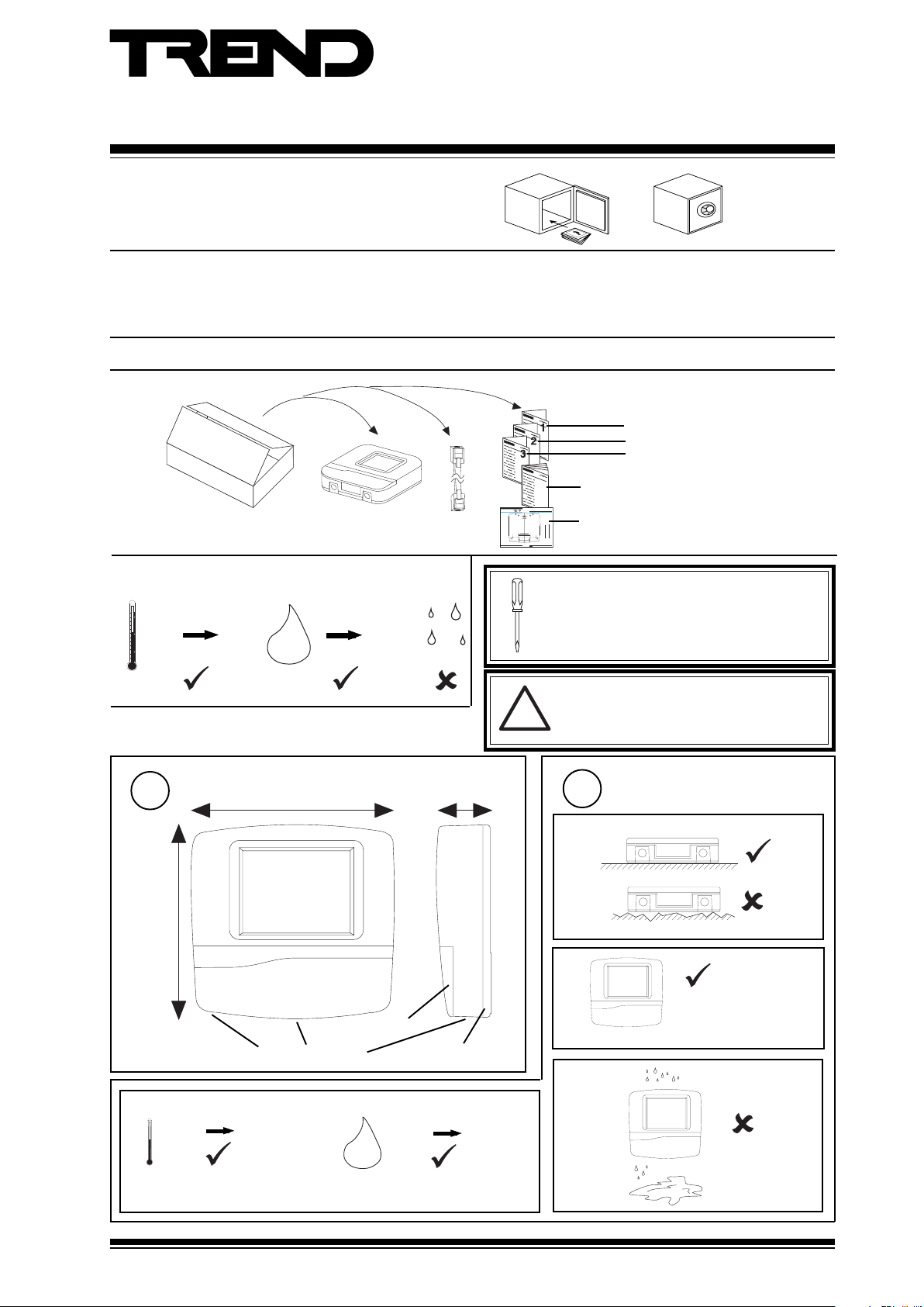
1.1 Unpacking 1 - 1
1.2 Storage 1 - 1
1.3 Installation Instructions - Mounting 1 - 1
SHEET 1: Installation Instructions
1.1 Unpacking
1.2 Storing
-10 °C
(14 °F)
+50 °C
(122 °F)
0
H2O
90 %RH
1.3 Installation - Mounting
2.1 Installation Instructions - Mounting (continued) 2 - 1
2.2 Installation Instructions - Configuration 2 - 1
3.1 Installation Instructions - Configuration 3 - 1
3.2 Disposal 3 - 3
3.3 End User Licence Agreement 3 - 4
IQVIEW../SM Installation
1
Instructions TG200711
Sheet 1
Sheet 2
Sheet 3
IQView Manual
IQVIEW/SURFACE Installation Instructions - Template
Important: Retain these instructions
three hole fixing
A
four hole fixing
B
Trend Control Systems Ltd reserves the right to revise this publication from time to time and make changes to the content hereof
without obligation to notify any person of such revisions or changes.
Trend Control Systems Ltd P.O. Box 34 Horsham Sussex RH12 2YF England Tel:+44 (0)1403 211888 Fax:+44 (0)1403 241608 www.trend-controls.com
B
B
A
rear cable entry cutout
A
B
B
IQVIEW/SURFACE Installation Instructions - Template TG200722 Issue 1/A 5/11/03
!
TE200719
Installation Instructions - Templ ate
IQVIEW/SURFACE
Touch Screen Display
NOTE: Print to size.
Check dimensions below
IQVIEW../SM Template
4"
10 cm
A
TG200722
1 - 1
It is recommended that the installation should
comply with the HSE Memorandum of Guidance
on Electricity at Work Regulations 1989.
For USA install equipment in accordance with
National Electric Code
WARNING
Other than removing front covers (see step 4),
do not attempt to open the unit. Failure to
comply may cause damage to the unit.
1
218 mm (8.58")
c
0 °C
(32 °F)
Dimensions
bottom cable access
(113 °F)
227 mm (8.94")
+45 °C
60 mm (2.36")
terminal access
rear cable access
0 %RH
80 %RH
H2O
Protection: IP42, NEMA3R
Requirements
2
a
b
The unit is UL rated as
'UL916, open energy
management equipment'
d
IQView../SM Installation Instructions TG200711 Issue 1/E 10/08/06
1 - 1
Page 2
IQView../SM Installation Instructions - Sheet 1
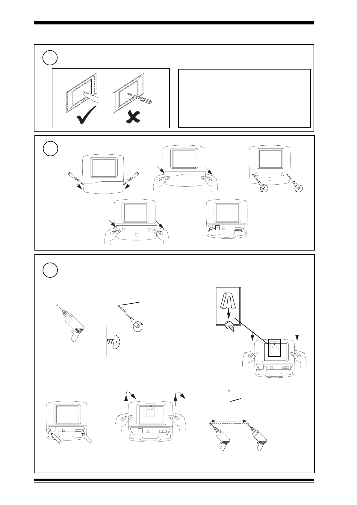
1.3 Installation - Mounting (continued)
Care of Touch Screen
3
Clean Screen
Remove dust and grease regularly by wiping
gently with a soft cloth such as that used for
spectacles
Remove Covers
4
a
bc
d
5
either by using 3 screws (e.g. for mounting on wall)
a
Mount Unit
b
M4, 5, or 6 (pan or CSK)
or No 10 or 12 (CSK)
e
c
rear view
de f
1 - 2
IQView../SM Installation Instructions TG200711 Issue 1/E 10/08/06
length depends on screw
head projection and screw
type
170 mm (6.69”)
Page 3
Installation Instructions - Sheet 1 IQView../SM
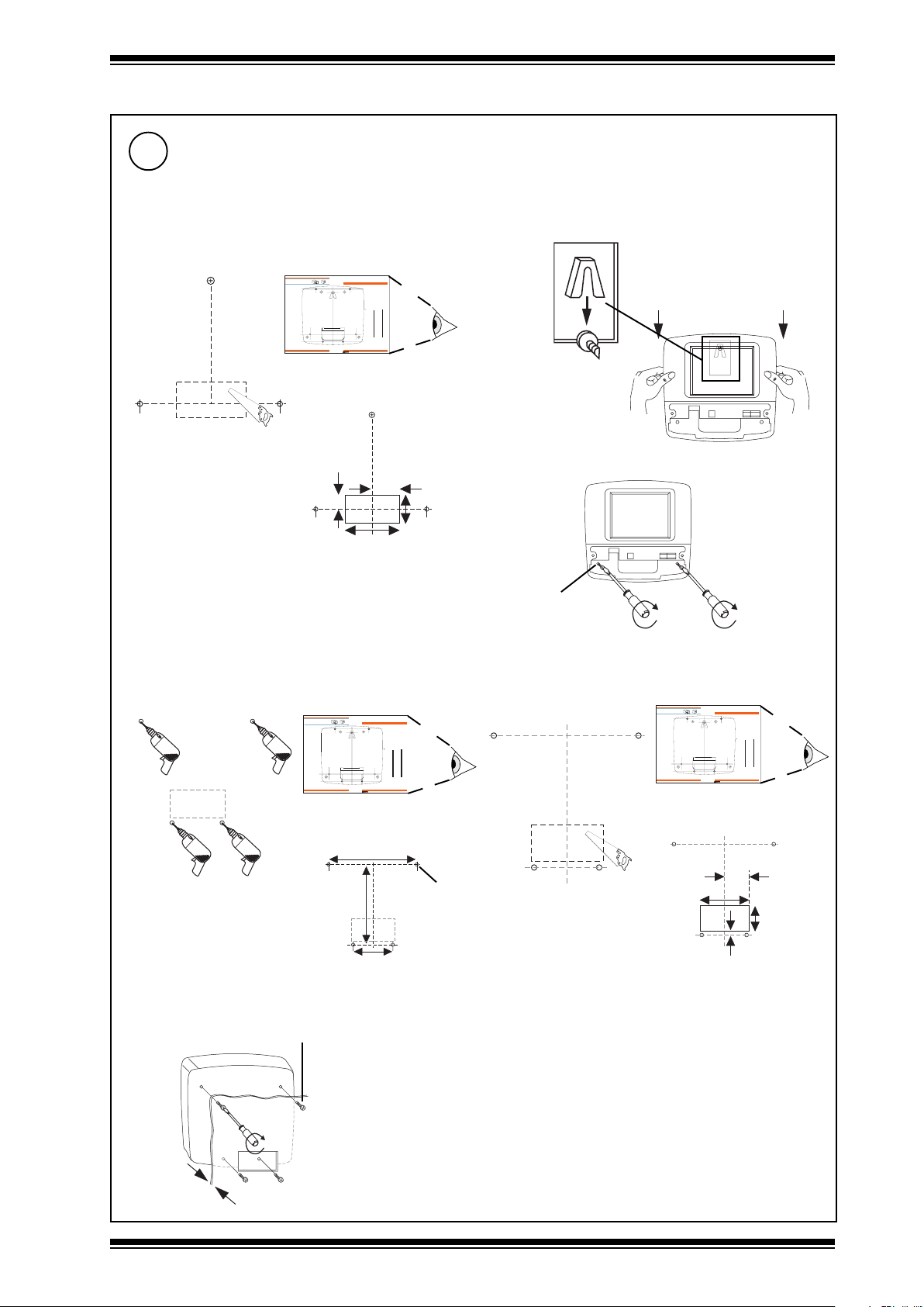
1.3 Installation - Mounting (continued)
5
Mount Unit (continued)
either by using 3 screws (continued)
g cut rear cable entry hole
if required
IQVIEW/SURFACE Installation Instructions - Template
Important: Retain these instructions
B
A
three hole fixing
A
four hole fixing
B
rear cable entry cutout
A
B
Trend Control Systems Ltd reserves the right to revise this publication from time to time and make changes to the content hereof
without obligation to notify any person of such revisions or changes.
Trend Control Systems Ltd P.O. Box 34 Horsham Sussex RH12 2YF England Tel:+44 (0)1403 211888 Fax:+44 (0)1403 241608 www.trend-controls.com
IQVIEW../SM template
TG200722
20 mm
(0.78”)
B
A
B
IQVIEW/SURFACE Installation Instructions - Template TG200722 Issue 1/A 5/11/03
80 mm
(3.15”)
Installation Instructions - Template
IQVIEW/SURFACE
Touch Sc ree n D is pl ay
NOTE: Print to size.
Check dimensions below
10 cm
40 mm
(1.57”)
h
rear view
4"
1 - 1
i
40 mm
(1.57”)
or by using 4 screws (e.g. mounting on a panel)
a
IQVIEW/SURFACE Installation Instructions - Template
Important: Retain these instructions
B
three hole fixing
A
four hole fixing
B
A
Trend Control Systems Ltd reserves the right to revise this publication from time to time and make changes to the content hereof
without obligation to notify any person of such revisions or changes.
Trend Control Systems Ltd P.O. Box 34 Horsham Sussex RH12 2YF England Tel:+44 (0)1403 211888 Fax:+44 (0)1403 241608 www.trend-controls.com
IQVIEW../SM template
TG200722
126 mm (4.96”)
c
4 x M4 x 16 mm
A
rear cable entry cutout
B
B
(3.78”)
196 mm
75 mm
(2.95”)
Installation Instructions - Template
IQVIEW/SURFACE
Touch Sc ree n D is pl ay
B
NOTE: Print to size.
Check dimensions below
4"
10 cm
A
1 - 1
IQVIEW/SURFACE Installation Instructions - Template TG200722 Issue 1/A 5/11/03
4 holes Ø 5 mm
2 x M4, 5, or 6
(No 10 or 12)
cut rear cable entry hole
b
if required
IQVIEW/SURFACE Installation Instructions - Template
Important: Retain these instructions
B
three hole fixing
A
four hole fixing
B
A
Trend Control Systems Ltd reserves the right to revise this publication from time to time and make changes to the content hereof
without obligation to notify any person of such revisions or changes.
Trend Control Systems Ltd P.O. Box 34 Horsham Sussex RH12 2YF England Tel:+44 (0)1403 211888 Fax:+44 (0)1403 241608 www.trend-controls.com
B
Installation Instruc tions - T emplat e
IQVIEW/SURFACE
Touch Sc ree n D is pl ay
B
A
NOTE: Print to size.
Check dimensions below
10 cm
rear cable entry cutout
A
B
IQVIEW/SURFACE Installation Instructions - Template TG200722 Issue 1/A 5/11/03
IQVIEW../SM template
TG200722
40 mm (1.57”)
80 mm (3.15”)
8 mm
(0.31”)
4"
1 - 1
40 mm
(1.57”)
10 mm
Max
IQView../SM Installation Instructions TG200711 Issue 1/E 10/08/06
1 - 3
Page 4
IQView../SM Installation Instructions - Sheet 1
1.3 Installation - Mounting (continued)
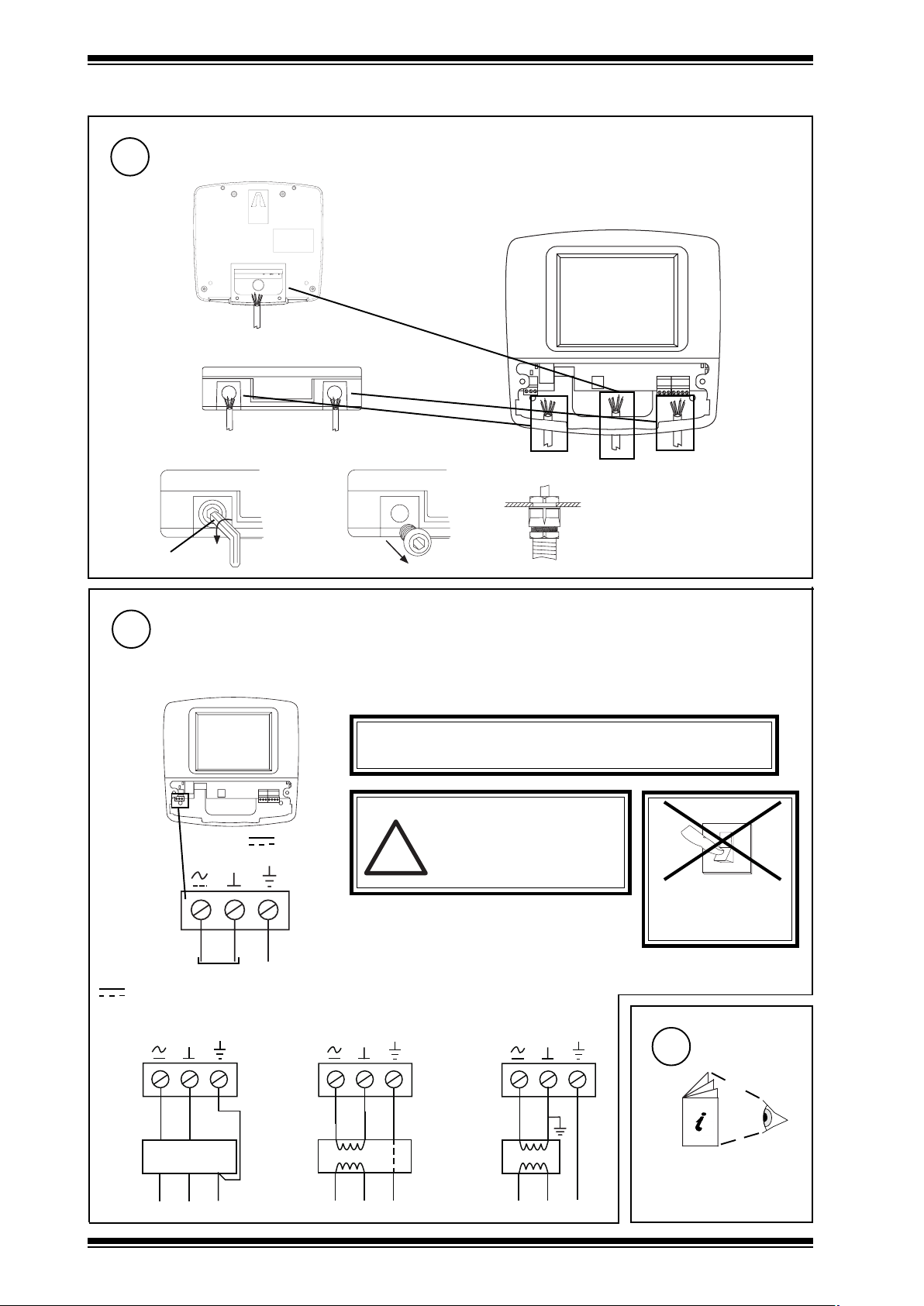
Route Cables
6
rear entry
bottom entry
fit M20 (¾”) cable glands
ab
8 mm Allen key
Connect Power
7
28 to 36 Vdc or 24 Vac ±10 %, 50/60 Hz
IQView consumption <= 24 VA maximum (13 VA typical).
The IQView consumes 13 VA, but the input power supply should be capable of 24 VA to cater for startup current
c
WARNING: This apparatus must be earthed (grounded)
(through input power supply earth (ground) terminal)
WARNING
Do not attempt to supply power
28 - 36 V
24 V ~
!
terminal size 0.5 to 2.5 mm2 (14 to 20 AWG)
through the RS232 connector (as
is done with NDP). This will
damage the unit.
SWITCH ON
0
I
DO NOT
24 Vac
~
28 Vdc
using 28 Vdc power supply
(e.g. PSR/230/24-2.5)
28 Vdc
L
100 to 240 Vac
1 - 4
24 Vac
+28V 0V
0V
PSR/230/24-2.5
N
E
E
E
E
using 230V/24V ac
transformer with isolated
output (e.g. ACC/24VAC)
24 Vac
ACC/24VAC
N
L
230 Vac
using 230V/24V ac
transformer with one
side earthed (grounded)
Configure
8
E
E
IQView../SM Installation Instructions TG200711 Issue 1/E 10/08/06
24 Vac
L
230 Vac
IQVIEW../SM Installation
N
E
2
Instructions - Sheet 2
Page 5

Surface Mount Touch Screen Display
!
SHEET 2: Installation Instructions
2.1 Installation - Mounting (continued)
Installation Instructions - Sheet 2
IQView../SM
Mount Unit
9
1
IQVIEW../SM
Installation Instructions -
Sheet 1
RJ11
CABLE/EJ105650
(supplied with IQView Mono, not IQView standard
version)
IQ1xx or CNC with 25 Way D type female
IQView
RJ11
CABLE/EJ105651
10
IQ3, IQ2xx, (some IQ1xx with RJ11)
IQView
25 way
D male
Connect RS232
only connection for IQView Mono,
if required for IQView (standard version)
2
IQ3xcite,
IQ2xx, IQ1xx
RJ11
IQ1xx with 5 in line plug
IQ1xx, CNC
RJ11
CABLE/EJ105651
WARNING
Do not attempt to supply power
through the RS232 connector (as
is done with NDP). This will
damage the unit.
IQView
CABLE/78-1772
(additional)
IQ1xx
5 in line socket
11
either connect to an Ethernet
hub
use standard Ethernet
cable
Connect Ethernet
if required, and if not connected to RS232 as in step 10
RJ45 e.g.
RJ45 PLUG UPT/10 (UTP)
RJ45 PLUG FTP/10 (FTP)
100 m
(max)
Ethernet hub e.g. FL HUB 10BASET
(packs of 10)
Cat 5e twisted pair e.g.
CAT5E UTP LSZH 305 M (UTP)
CAT5E FTP LSZH 305 M (FTP)
305 m, 333 yds cable
IQView (standard version) only
or direct connect to an IQ3 or EINC
100-240 V
RJ45
RJ45
standard Ethernet cable
OK RX
XCITE/XA crossover adaptor
order separately (XCITE/XA/5
pack of 5)
IQView../SM Installation Instructions TG200711 Issue 1/E 10/08/06
2 - 1
Page 6

IQView../SM Installation Instructions - Sheet 2
T
T
1
2.1 Installation - Mounting (continued)
12
Connect Current Loop
if required and if not connected to RS232 as in step 10 or to Ethernet as in step 11
elbaCduab2k1duab8k4duab6k9duab2k91
2819nedleB
7029nedleB
(
)1678nedleB
)3278nedleB(
002/FH/22/1/1/PTdnerT
002/FH/22/2/2/PTdnerT
m0001
m0001
m0001
m0001
polarity independent
terminal size 0.5 to 2.5 mm2 (14 to 20 AWG)
4 wire
T R
T R
T R
T R
R
R
T
T
additional terminals
m0001
)sdy0901(
m0001
)sdy0901(
m0001
)sdy0901(
m0001
)sdy0901(
T- T+ R- R+
4 5 6 7
IQView (standard version) only
fo.oN
)sdy0901(
)sdy0901(
)sdy0901(
)sdy0901(
m0001
m0001
m007
)sdy567(
m005
)sdy545(
m007
67(
)sdy0901(
m005
)sdy0901(
m053
m052
seriW
2
)sdy5
2
)sdy545(
2
)sdy083(
4
)sdy072(
Network Engineering
Manual, 92-1735
2 wire
T R
T R
T R T R
T
T
R
R
X
R
R
T- T+ R- R+
4 5 6 7
X
13
Connect Relay Output
AC rating: 62.5 VA e.g 40 Vac max @ 1.5 A, 24 Vac @2.5 A
if required (for alarm notification)
DC rating: 60 W e.g. 40 Vdc max @ 1.5 A, 24 Vdc @ 2.5 A
Note that UL rating applies up to 30V maximum
power
Load on when
Alarm present,
(Relay energised)
3
2
1
power
Load on when
Alarm not present,
(Relay off)
3
2
1
WARNING: The wires may be connected to
hazardous voltages. Disconnect
power before attempting any wiring.
Replace Covers
14
a
b
load
load
c
Note that the relay output alarm action
must be enabled (it is enabled by
default), see 2.2 step 15.
1 2 3
Arc suppression
recommended
Relay Output Arc Suppression
Installation Instructions TG200208
d
2 - 2
IQView../SM Installation Instructions TG200711 Issue 1/E 10/08/06
Page 7

Installation Instructions - Sheet 2 IQView../SM
2.2 Installation - Configuration
Read Licence
1
Read and agree to End User
3
Licence Agreement (these
instructions Sheet 3 Section 2)
Check Power LED
3
Specify Site Connection
4
power
(blue)
2
Switch On
0
I
Check input power supply
alarm present
(a) Enter ‘Site Name’
Note that for IQView Mono, the RS232 connection will be selected, all
other selections will not be available, and the user should jump to stage
(d) below to ‘Connect to CNC’/’RS232’ and enter the baud rate.
(b) Select first connection stage:
either ‘Connect to CNC’ - If connecting to either Ethernet vCNC
or ‘Connect as Device’ - If IQView is device on current loop
(c ) Select second connection stage:
If ‘Connect to CNC’ was selected
either ‘Ethernet (vCNC)’ -If connecting to vCNC in EINC or IQ3
or ‘RS232’ - If connecting to CNC module, or IQ controller’s local supervisor CNC (sCNC)
If ‘Connect as Device’ was selected
either ‘Current Loop Lan’ - If connecting IQView as device on a current loop Lan (using IQView’s internal CNC)
or ‘Ethernet Lan’ - If connecting IQView as device on Ethernet Lan (using IQView’s internal vCNC)
(d) Setup up communication parameters
If ‘Connect to CNC’/’Ethernet (vCNC)’ - Set IP address (or host name) of IQ3 or EINC and port number of the vCNC
If ‘Connect to CNC’/’RS232’ - Set baud rate for communication between IQView and CNC or IQ
controller’s local supervisor port to match the baud rate set in the remote device (controller local supervisor port
baud rate is normally 9600 baud)
If ‘Connect as Device’/’Current Loop Lan’ - Set up IQView’s Lan number (to be unique on internetwork and to match
other devices on Lan), network address (to be unique on Lan), and baud rate (to be same as other nodes on Lan)
If ‘Connect as Device’/’Ethernet Lan’ - Set up IQView’s Lan number (to be unique on internetwork and to match
other devices on Lan) and network address (to be unique on Lan). Set up UDP port to match address used by rest
of IQ system
(vCNC in EINC or IQ3) or RS232 (CNC
module or IQ controller’s local
supervisor port)
Lan (using IQView’s internal CNC),
or device on Ethernet Lan (using
IQView’s internal vCNC)
(e) The IQView will now attempt to find its own Lan number (from an INC). If successful it will try to learn the internetwork
and display all the associated Lan icons including local Lan, if unsuccessful it will just display its own Lan icon (with
Lan number 0).
If either Ethernet (vCNC), or Ethernet Lan have been selected, the default is for the Ethernet IP address details
to be automatically set up. If DHCP server is operating it will set up the IP address details, if not the details will be
set up by auto-negotiation with the other devices on the Ethernet Lan.
For Ethernet connections proceed with step 5 and for all other connections go to step 6.
IQView../SM Installation Instructions TG200711 Issue 1/E 10/08/06
2 - 3
Page 8

IQView../SM Installation Instructions - Sheet 2
2.2 Installation - Configuration (continued)
Set up IQView’s Ethernet Settings
5
if either ‘Connect to CNC’/’Ethernet vCNC’, or ‘Connect as Device’/’Ethernet Lan’ set up as above.
Note that if auto IP addressing is required (as per default) go to (d)
(a) Tap on IQView menu icon in the menu rail on the
top of the screen, and tap on ‘Settings/Network (Ethernet)’.
(b) Change IP address source:
from ‘Obtain IP address via DHCP’ (default)
IP settings being set up automatically
to ‘Specify an IP address’
IP settings being set up manually
(c ) Enter IP Address
Note that the these details can be set up using IPTool (v1.1 or greater) rather than tapping them in on the screen
(d) If ‘Obtain IP address via DHCP’ selected, and there is no DHCP server on the segment, then enter
Note that the these details can be set up using IPTool (v1.1 or greater) rather than tapping them in on the screen
Subnet Mask
Default Gateway - router IP address (if communications
cross router)
Select servers tab and enter
WINS Server IP Address(es) (if host names being used
across router)
Go to (e)
Default Gateway - router IP address (if communications cross router)
Select servers tab and enter
WINS Server IP Address(es) (if host names being used across router)
IQView (standard version) only
(e) Tap to close the box, and the unit will reset.
(f ) If network is to cross router enter remote devices’ IP addresses
(or host names) and subnet masks using IPTool
(g) Re - initialise the site connection by selecting and
‘ReInit Connection’.
The IQView will now attempt to find its own Lan number (from
an INC). If successful it will try to learn the internetwork, if
unsuccessful it will just display its own Lan icon.
Note that the time taken for the system to be available for mapping will
depend on the type of Ethernet connection. If connecting to ‘Connect to
CNC’, ‘Ethernet vCNC’ it can be instantaneous (if the rest of the system
is setup). If connecting ‘Connect as Device‘, ‘Ethernet Lan’ it can take
from <30s to <130s depending on its IP address and whether the network
crosses a router.
Learn Entire Site
6
(a) The IQView will display the adjacent dialogue box. Recommend select
‘Yes’ to learn of all controllers. The box times out after 5 s and will learn
the all controllers by default. (Selecting ‘No’ means that the controllers
should be learnt later when user selects the learn site/Lan functions).
2 - 4
7
3
Configure
IQVIEW../SM Installation
Instructions - Sheet 3
IQView../SM Installation Instructions TG200711 Issue 1/E 10/08/06
Page 9

Surface Mount Touch Screen Display
SHEET 3: Installation Instructions
3.1 Installation - Configuration (continued)
Installation Instructions - Sheet 3
IQView../SM
Mount Unit
8
2
IQVIEW../SM
Installation Instructions -
Sheet 2
The connection can be checked at any time by tapping on the
comms icons in the bottom right corner of the display.
(green flicker) Icons have been tapped and the check
is in progress
(green steady) Communications OK
(red steady) Communications fail
Remove Covers
10
a
if ‘Connect to CNC’/’Ethernet (vCNC)’, ‘Connect as Device’/’Ethernet Lan’, or ‘Connect as Device’/’Current Loop Lan’
Check Connection
9
A falure to connect in steps 4, 5, or 6 will produce a dialogue box detailing the reason
for failure.
b
3
c
d
Check Ethernet OK LED
11
if ‘Connect to CNC’/’Ethernet (vCNC)’ or ‘Connect as Device’/’Ethernet Lan’
Ethernet OK
(green)
Check Ethernet Connection and/or vCNC
IQView../SM Installation Instructions TG200711 Issue 1/E 10/08/06
e
3 - 1
Page 10

IQView../SM Installation Instructions - Sheet 3
T
K
3.1 Installation - Configuration (continued)
Check Current Loop Lan LEDs
12
if ‘Connect as Device’/’Current Loop Lan’
T- T+ R- R+
4 5 6 7
OK
IQView Faulty
X
RX
O
T- T+ R- R+
4 5 6 7
aRX
(yellow)
bTX
(yellow)
c OK
(green)
IQView
IQView
?
IQView
?
Network Address Invalid
OK
Check network cabling for
short circuits with a
multimeter (NOT Megger)
Check baud rate. Power
O
I
up other nodes until faulty
node is found (OK ).
Correct fault.
0,2,3 or >119
Replace Covers
if appropriate
13
a
b
Test System
14
(a) Tap on controller icon in navigator e.g. (IQ2 controller)
(b) Tap on controller menu icon e.g.
(c) Tap on ‘Modules’/’Sensors’ on drop down menus
(d) Check sensors display
c
d
3 - 2
IQView../SM Installation Instructions TG200711 Issue 1/E 10/08/06
Page 11

Installation Instructions - Sheet 3 IQView../SM
3.1 Installation - Configuration (continued)
Test Relay Output
15
if required
(a) Tap in the menu rail on top of the screen and tap on
‘Settings’/’Alarms’
(b) Tap on the relay action (to select relay action)
(c) Tap to close the box
(d) Tap in bottom rail of screen
(e) Tap and choose ‘Turn alarm on’ from drop down menu
(f) Listen for relay to click and check relay operates the connected device
(g) Tap in bottom rail of screen to stop alarm test.
Configure IQView
16
if required
IQView Manual TE200719
The following facilities may be configured by tapping and selecting the facility from the drop down menu.
ytilicaFstluafeDfiegnahCsmetI
sresUdelbasidytiruceSderiuqerytiruceS tesydaerla(sresunimdAdnatseuGdnasresuelb
mralA
gnildnah
emiTmorftratS
yalpsiDtuoemitthgilkcaB
egaugnaL)KU(hsilgnE
.detpeccasmralallA
DELdnarezzuB
snoitcamrala
cs
pu
hsalf;delbane
yalerdnaneer
delbasid
noetaddenifednu
dnapurewop
tnuoc
paT.s006ottes
dnuosneercs
delbasid
dnasneercs
stamrof
tnemnorivne
degnahceboterasnoitca
nahcebottuoemitthgilkcabfI
.delbaneebotdnuosneercs
deriuqeregaugnaltnereffidfI ,etadsegnahcdnasyalps
mralaro,deriuqererasmralaemosylnO
)deriuqerfi(srellortnocgnisinorhcnys
patrodeg
tiusotdetsujdaebnactsartnoC
etarbilaceR.elgnagniweiv/
anE
ebnactahwfonoitinifed
hT
.delbasid/delbaneyllaudividni
etad/emitrofdesU.deriuqeretaddnaemitfI
rofdna,stnemgdelwonkcamralagnipmats
snoitcnufgnorwtcelesspatneercsfineercs
etaddnaemits'weiVQI
noitar
bilacneercS,tsujda
idneercssetalsnartyltnerruC
hsilgnE,)KU(hsilgnE
.)hsidewSdna,hsinapS,naigewroN
resuhcaE.deddaebnacsresueroM.)stluafedotpu
adna,tuoemit,NIP,drowssap,emanresuasah
.degnahcrodessecca
mraladeviecerehtotdeddasmralafosepyte
ebn
ac)yalerdna,neercshsalf,DELhsalf,rezzub(
tsartnoC,ffo/nodnuosneercspaT,tuoemiTthgilkcaB
,hsinaD,hcnerF,namreG,)SU(
,eludom,lareneg,lacitircmorfdetcelesebnacyalpsid
snoitcamralaehT.nwonknuro,ssecca,rellaid,krowten
edulcnisegaugnal(stamrofrotarapeslamiceddna,emit
3.2 Disposal
WEEE Directive :
At the end of their useful life the packaging and
product should be disposed of by a suitable
recycling centre.
Do not dispose of with normal household waste.
Do not burn.
IQView../SM Installation Instructions TG200711 Issue 1/E 10/08/06
3 - 3
Page 12

IQView../SM Installation Instructions - Sheet 3
3.3 End User Licence Agreement
EULA Terms
· You have acquired an IQView (“Device”) that includes software licensed by Trend Control Systems Ltd from one or more
software licensors (“Trend Control Systems Ltd Software Suppliers”). Such software products, as well as associated
media printed materials and “online” or electronic documentation (“SOFTWARE”) are protected by international intellectual
property laws and treaties. The SOFTWARE is licensed, not sold. All rights reserved.”
· IF YOU DO NOT AGREE TO THIS END USER LICENSE AGREEMENT (“EULA”), DO NOT USE THE DEVICE OR COPY THE
SOFTWARE. INSTEAD, PROMPTLY CONTACT Trend Control Systems Ltd FOR INSTRUCTIONS ON RETURN OF THE UNUSED
DEVICE(S) FOR A REFUND. ANY USE OF THE SOFTWARE INCLUDING BUT NOT LIMITED TO USE ON THE DEVICE will
constitute your agreement to the EULA (or Ratification of any previous consent).
· GRANT OF SOFTWARE LICENSE. This EULA grants you the following license:
• You may use the SOFTWARE only on the DEVICE
• NOT FAULT TOLERANT. THE SOFTWARE IS NOT FAULT TOLERANT. TREND CONTROL SYSTEMS LTD HAS
INDEPENDENTLY DETERMINED HOW TO USE THE SOFTWARE IN THE DEVICE, AND TREND CONTROL SYSTEMS
LTD’S SOFTWARE SUPPLIERS HAS RELIED UPON TREND CONTROL SYSTEMS LTD TO CONDUCT SUFFICIENT
TESTING TO DETERMINE THAT THE SOFTWARE IS SUITABLE FOR SUCH USE.
• NO WARRANTIES FOR THE SOFTWARE. THE SOFTWARE is provided “AS IS” and with all faults. THE ENTIRE
RISK AS TO SATISFACTORY QUALITY, PERFORMANCE, ACCURACY, AND EFFORT (INCLUDING LACK OF
NEGLIGENCE) IS WITH YOU. ALSO, THERE IS NO WARRANTY AGAINST INTERFERENCE WITH YOUR ENJOYMENT
OF THE SOFTWARE OR AGAINST INFRINGEMENT. IF YOU HAVE RECEIVED ANY WARRANTIES REGARDING THE
DEVICE OR THE SOFTWARE, THOSE WARRANTIES DO NOT ORIGINATE FROM, AND ARE NOT BINDING ON, TREND
CONTROL SYSTEMS LTD’S SOFTWARE SUPPLIERS.
• Note on Java Support. The SOFTWARE may contain support for programs written in Java. Java technology is
not fault tolerant and is not designed, manufactured, or intended for use or resale as online control equipment in
hazardous environments requiring fail-safe performance, such as in the operation of nuclear facilities, aircraft
navigation or communication systems, air traffic control, direct life support machines, or weapons systems, in which
the failure of Java technology could lead directly to death, personal injury, or severe physical or environmental
damage. Sun Microsystems, Inc. has contractually obligated Trend Control Systems Ltd’s software suppliers to make
this disclaimer.
• No Liability for Certain Damages. EXCEPT AS PROHIBITED BY LAW, TREND CONTROL SYSTEMS LTD’S SOFTWARE
SUPPLIERS SHALL HAVE NO LIABILITY FOR ANY INDIRECT, SPECIAL, CONSEQUENTIAL OR INCIDENTAL
DAMAGES ARISING FROM OR IN CONNECTION WITH THE USE OR PERFORMANCE OF THE SOFTWARE. THIS
LIMITATION SHALL APPLY EVEN IF ANY REMEDY FAILS OF ITS ESSENTIAL PURPOSE. IN NO EVENT SHALL
TREND CONTROL SYSTEMS LTD’S SOFTWARE SUPPLIERS BE LIABLE FOR ANY AMOUNT IN EXCESS OF U.S.
TWO HUNDRED FIFTY DOLLARS (U.S.$250.00).
• Limitations on Reverse Engineering, Decompilation, and Disassembly. You may not reverse engineer,
decompile, or disassemble the SOFTWARE, except and only to the extent that such activity is expressly permitted
by applicable law notwithstanding this limitation.
• SOFTWARE TRANSFER ALLOWED BUT WITH RESTRICTIONS. You may permanently transfer rights under this
EULA only as part of a permanent sale or transfer of the Device, and only if the recipient agrees to this EULA. If
the SOFTWARE is an upgrade, any transfer must also include all prior versions of the SOFTWARE.
Manufactured for and on behalf of the Environmental and Combustion Controls Division of Honeywell Technologies Sàrl, Ecublens, Route
du Bois 37,Switzerland by its Authorized Representative, Trend Control Systems Limited.
Trend Control Systems Limited reserves the right to revise this publication from time to time and make changes to the content
hereof without obligation to notify any person of such revisions or changes.
Trend Control Systems Limited
P.O. Box 34, Horsham, West Sussex, RH12 2YF, UK. Tel:+44 (0)1403 211888 Fax:+44 (0)1403 241608 www.trend-controls.com
Trend Control Systems USA
6670 185th Avenue NE, Redmond, Washington 98052, USA. Tel: (425)869-8400, Fax: (425)869-8445 www.trend-controls.com
3 - 4
IQView../SM Installation Instructions TG200711 Issue 1/E 10/08/06
 Loading...