

Page 1
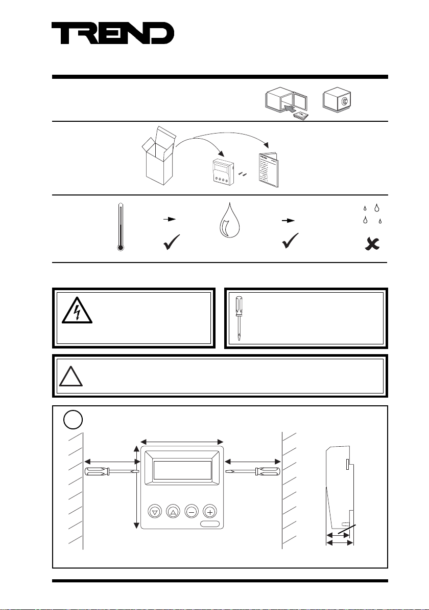
Important: Retain these instructions
1 Unpacking
2 Storing
-10 °C
+14 °F
+50 °C
+122 °F
3 Installation
HO
2
Installation Instructions
SDU-LON
Smart Display Unit
SDU-LON Installation
Instructions TG200599
0 %RH
95 %RH
WARNING: Other than removing
front panel (step 3), do not open unit.
DANGER high voltage. No
serviceable parts inside.
Note that this product may involve LONWORKS® system integration as referred to in step
12: this procedure should only be performed by an installer with L
!
expertise.
Dimensions
1
90 mm (3.54”)
150 mm (6”) 150 mm (6”)
90 mm (3.54”)
SDU-LON Installation Instructions TG200599 Issue 2, 6/10/08
It is recommended that the installation should
comply with the HSE Memorandum of Guidance
on Electricity at Work Regulations 1989.
For USA install equipment in accordance with
the National Electric Code.
ONWORKS engineering
25 mm
(0.98”)
30 mm (1.18”)
1
Page 2
SDU-LON Installation Instructions
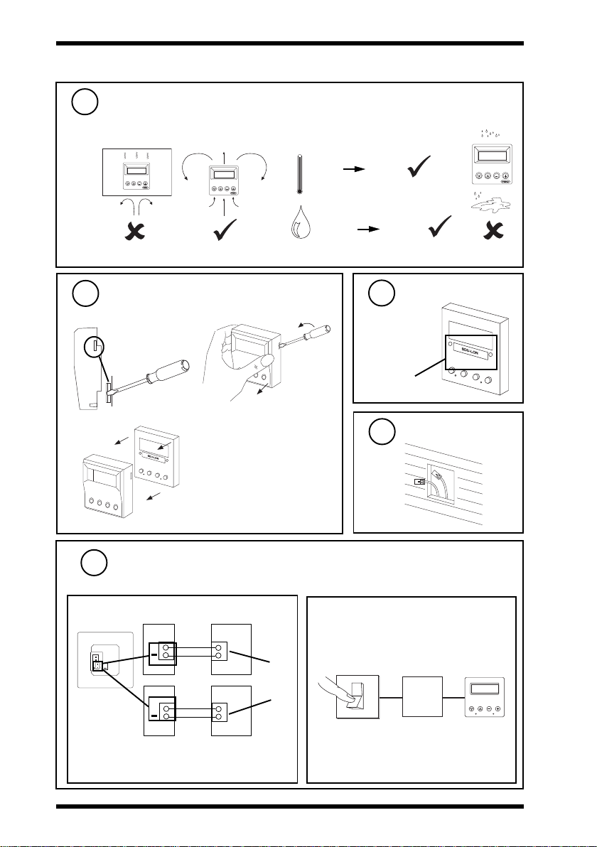
3 Installation (continued)
Requirements (continued)
2
a
Remove Front Panel
3
a
c
b
-10 °C
+14 °F
0 %RH 90 %RH
HO
2
+40 °C
+104 °F
4
c
Check SDU type
b
Check SDU-LON
Route Cables
5
Configure SDU
6
to change operating mode, restrictive set, or language
a Connect Input Power
+24 Vdc
0 Vdc
+24 Vac (L)
+24 Vac (N)
*
24 Vdc Power
Supply
24 Vac Power
Supply
SDU
+
+
SDU
+
* If one side of the 24 Vac input power is connected
to 0 V, that side must be connected to the SDU
- (negative) terminal
2
b Switch on Power
24 Vdc
15 mA
ensure
correct
polarity
24 Vac
15 mA
SDU-LON Installation Instructions TG200599 Issue 2, 6/10/08
O
I
24 V
Power
Supply
SDU
1 2 3 4
S P E NG
Page 3
Installation Instructions SDU-LON
S P E N G
1 2 3 4
Confi g Update
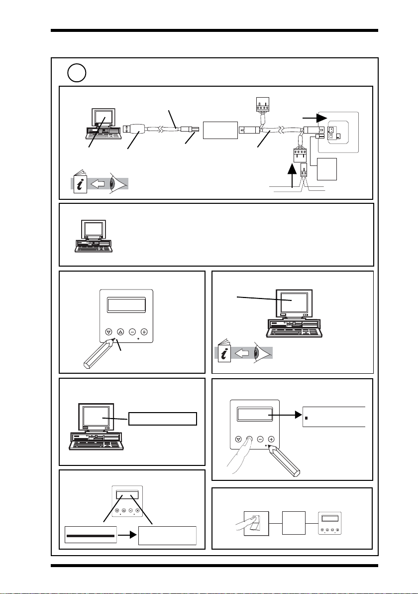
3 Installation (continued)
Configure SDU (continued)
6
c Connect to PC
supplied with LCI/USB
SET,
SDU Tool
USB type A
USB type B
LCI Installation Instructions
TG200429
d Set up SDU Configuration File
SDU Tool
Backup File to Disk
e Identify SDU to SDU Tool
1 2 3 4
S P E N G
SP - service pin
SDU-LON
LCI/USB
+
supplied with LCI/USB
24 V
power
supply
l
LONWORKS
network
L
ONWORKS
network
Set up:
Mode Unrestricted/Restricted
Home Page Show/Don’t show
Restrictive mode list Select required modules
Language Translation of standard text
f Download Language
SET
SDU Tool
SDU Data Sheet TA200559
SDU Tool Manual TE200600
Select
Language
Download to
SDU
g Download Completed
Download Complete
i Transfer Completed
1 2 3 4
S P E N G
Config Update
SDU-LON Installation Instructions TG200599 Issue 2, 6/10/08
h Set SDU into Download Mode
j Switch off Input Power
SDU
O
24 V
I
1234
SP ENG
3
Page 4
SDU-LON Installation Instructions
3 Installation (continued)
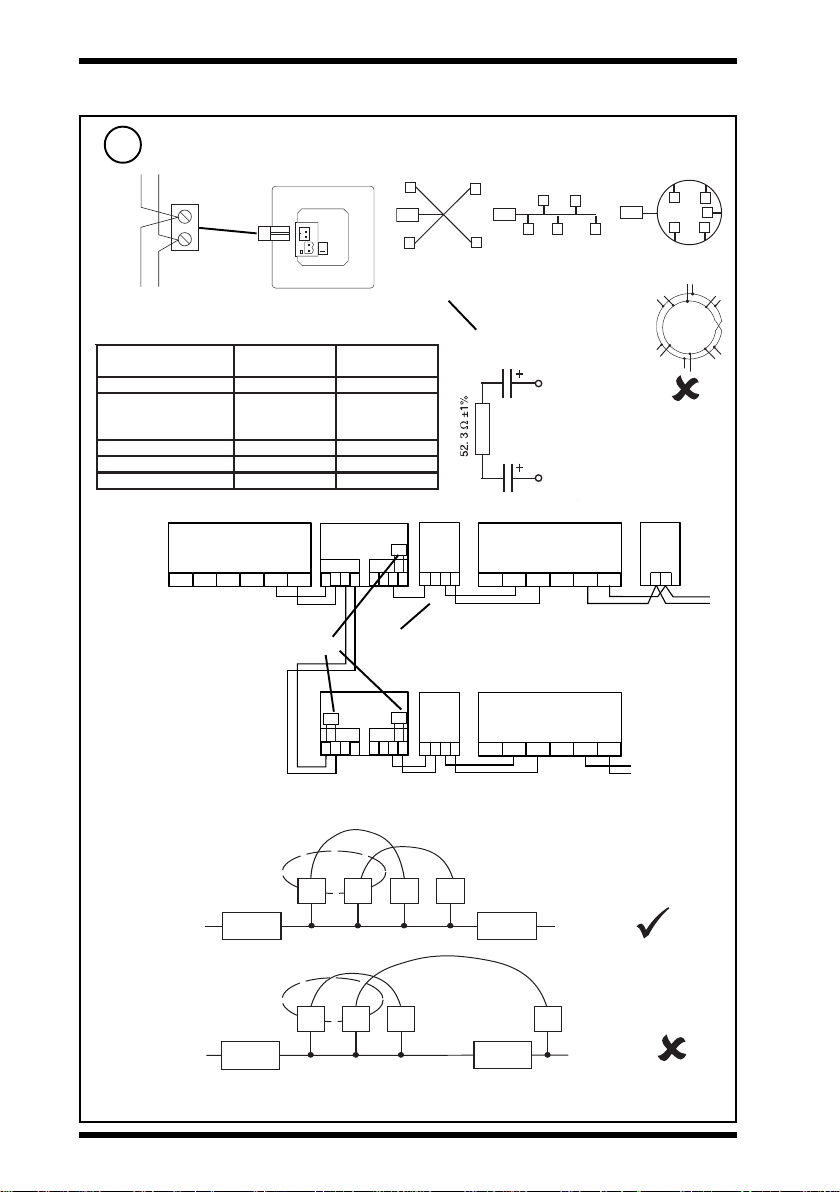
Connect to LONWORKS Network
7
Lon
T e r m i n a to r
topology
Do not allow wires
to cross on a loop
SDU
xcite
LonB
+
Lon
Normal Trend Lan cable is not recommended.
Do not use screened cable.
elbaChtgnelsubxaM
20158nedleB)sdy545(m005)sdy545(m005
metsysQI
002/FH/61/0/1/PT
)1748nedleB(
)sdy545(m005)sdy034(m004
GWA22,VIleveLLU)sdy545(m005)sdy034(m004
8.0x2x2Y)tS(YJ)sdy545(m005)sdy053(m023
GWA42,5.taCA865AIT)sdy094(m054)sdy072(m052
Terminal size 0.5 to 2.55 mm2 (14 to 20 AWG)
SCN
LINC
LonA
LonB LonA
SCN
LonB
IQLROUTER
A
6
45
7
Recommend terminate at
LINC or Router.
e.g. use IQLRouter integral
terminators
T e r m i n a to r
Star topology Ring
T e r m i n a to r
Bus topology
* Terminate bus at one end only
Terminator
e.g. LONTERMINATOR
otedonxaM
edon
1 0 0 mF , 5 0 V m i n
1 0 0 mF , 5 0 V m i n
89
IQL
T
B
10
11
y
z
x
w
SCN
LonA
LonB LonA
LONC
SCN
Maximum 64 nodes per LONWORKS segment
Maximum 40 IQLs (and LONCs) per Lan
IQLROUTER
T
A
6
45
7
89
IQL
T
B
10
11
xyzw
SCN
LonA
LonB LonA
LONC
SCN
LonB
Note that: If two SDU/LONs are associated with IQLs which are on the same Lan, the SDU-LONs
must be on the same segment (i.e. on the same section of L
LONWORKS
network
ONWORKS
L
network
LW
ON ORKS
Router
LW
ON ORKS
Router
associated
Virtual
Lan
IQL IQL
associated
Virtual
Lan
IQL
IQL
associated
SDU SDU
segment
SDU SDU
segment
ONWORKS network separated by routers).
L
ONWORKS
network
L
ONWORKS
network
associated
LW
ON ORKS
Router
LW
ON ORKS
Router
If the system is installed on a LonWorks Management Tool (as in step 12), this rule does
not apply.
4
SDU-LON Installation Instructions TG200599 Issue 2, 6/10/08
Page 5

Installation Instructions SDU-LON
S P E N G
1 2 3 4
3 Installation (continued)
Connect Input Power
8
SDU
+
+
SDU
+
* If one side of the 24 Vac input power is connected to 0 V, that side must be connected to the SDU - (negative)
terminal
Switch on Input Power
9
+24 Vdc
+24 Vac (L)
+24 Vac (N)
0 Vdc
*
24 Vdc Power
Supply
24 Vac Power
Supply
SDU
24 Vdc
15 mA
24 Vac
15 mA
ensure
correct
polarity
10
Check Start Up Reset
Comms failure
or no sensor set up
Displays first
labelled sensor if set to defaults
11
Check LONWORKS Network Connected
O
I
Connect to IQ
SENSOR 1
FLOOR 1 Space Temp
20.3 DegC
+
24 V Power
Supply
1 2 3 4
S P E N G
* One of these will show ‘Failed’
SDU-LON V2.04
FLASH CHECK *
EEPROM CHECK *
SDU-LON V2.04
FLASH CHECK OK
EEPROM CHECK OK
LONWORKS (green)
SDU faulty
installed on L
SDU-LON V2.04
failed to install on LONWORKS
network; check step 7
ONWORKS network
SDU-LON Installation Instructions TG200599 Issue 2, 6/10/08
5
Page 6

SDU-LON Installation Instructions
3 Installation (continued)
12
Install on LONWORKS Management Tool
If other IQ System devices on LONWORKS are installed on LONWORKS Management Tool (LMT).
When installing SDU-LON on L
ONWORKS Management Tool, push service pin button when
requested.
See LONWORKS network management tool
ONWORKS Products
ONWORKS
SDU Data Sheet TA200559
ONWORKS network
for L
1 2 3 4
S P E N G
service pin button
manual. See IQ System L
Engineering Manual (TE200292). L
System integrator must have LONWORKS
engineering expertise.
variables (NVs)
The SDU must also be associated with its IQL using the LMT
The following network variables need to be set up using the LMT:
nciInstallState: set to CFG_EXTERNAL
nciHostNodeAddr: set to associated IQL LonWorks node address
nciSubnetAddr: set to associated IQL LonWorks subnet address
nciMsgCode: set message code of associated IQL
nciDomainIndex: set to domain index of associated IQL
13
Associate SDU with its IQL
Either use IQLTool2 running in SET and connected to a
ab
Connect t o IQ
“Connect to IQ”
1234
SP ENG
not if installed on L
LONWORKS network using LCI or use buttons as follows:
“Press IQL
Service Pin”
ONWORKS Management Tool
Press IQL Serv ice PIN
1234
SP ENG
cd
L AN
O /S
S tra t eg y
: : : : :
N ID
IN 3
IN 1
D O5 IN 2
D O2
D O3
D O1
D O4
C OM
C OM
C OM
24 V
24 V
~
~
+
I Q
L
L O N
2 4 V a c
4 secs
service pin button
14
Mount Unit
or panel
60 mm
Standard UK pattress wall box
60 mm
2 off (M3.5 x 35 mm)
Ø 4 mm
(M3.5
screw)
46 mm
50 mm
Ø 4 mm
(M3.5
screw)
screws provided
6
SDU-LON Installation Instructions TG200599 Issue 2, 6/10/08
Page 7

Installation Instructions SDU-LON
S e n s o r 1
F l o o r 1 S p a c e T e m p
2 0 .3 D e g C
3 Installation (continued)
15
Replace Front Panel
16
Check Display
1234
Displays first labelled
sensor if set to
defaults
17
Check Operation - Monitor
Note that the full sequence listed below may only be shown in Unrestricted modes. The Restricted
modes show only those pages on the Restricted list. The Home page is optional (see step 6d).
Plant Roo m 1
20/03/02 08:04
1234
S e n s o r 1
F l o o r 1 S p a c e T e m p
2 0 . 3 D e g C
1234
S e n s o r 1
F l o o r 1 S p a c e T e m p
2 0 . 3 D e g C
1234
Home page
Sensor
Knob
Sensor 1
Sensor 2
Switch
Driver
Digital Input
Time Zone
Time
Calendars
Note that if there are no modules of
type (sensors, knob, switch, driver,
digital input) set up with a label it will
jump to the next type display.
SDU-LON Installation Instructions TG200599 Issue 2, 6/10/08
Sensor (last)
Note that only modules with labels (not
necessarily sequential) will be displayed.
7
Page 8

SDU-LON Installation Instructions
3 Installation (continued)
18
Check Operation - Adjust
Knob 1
Room 1 Setpoint
20.01 DegC
1234
Digital
Analogue
Units
20.32
Tenths
Hundreths
20.32
20.32
Knob 1
Room 1 Setpoint
20.01 DegC
1234
OFF
ON
Knob 1
Room 1 Setpoint
20.01 DegC
1234
if PIN required
see step 19
8
SDU-LON Installation Instructions TG200599 Issue 2, 6/10/08
Page 9

Installation Instructions SDU-LON
T
1234
3 Installation (continued)
19
Enter PIN
If required
P I N 5 * * **
1234
a
b
c
d
e
f
g
h
5 * * *
PIN
PIN X
PIN X X
PIN X X X
5 * *
5 *
S e n s o r 1
F l o o r 1 S p a c e T e m p
5
2 0 . 3 D e g C
20
SDU-LON Installation Instructions TG200599 Issue 2, 6/10/08
Set Contrast
TEXT
TEXT
TEXT
9
Page 10

SDU-LON Installation Instructions
SP
ENG
1 2 3 4
3 Installation (continued)
21
Set SDU Mode
If required
Note that the alarm log is permanently disabled
for SDU-LON so the SDU mode selects restricted/
unrestricted and home page
a Remove front panel - see step 3
b Set mode
S e n s o r 1
F lo o r 1 S p a c e T e m p
2 0 .3 D e g C
1 2 3 4
S P E N G
Note that if the home page is enabled, the controller’s identifier [R(D)] should be set up, otherwise
the first line of the home page will show the label of the previous item displayed.
S e n s o r 1
F l o o r 1 S p a c e T e m p
2 0 . 3 D e g C
Display Mode = 1
Display Mode = 7
Default - Display Mode 0:
No home page, alarm log disabled
edoMteSegaP
0detcirtsernUoN
1detcirtsernUseY
2detcirtsernUoN
3detcirtsernUseY
4detcirtseRoN
5detcirtseRseY
6detcirtseRoN
7detcirtseRseY
emoH
egaP
c Replace front panel - see step 15
22
Engineering Resets
If need temporary Unrestricted mode for commissioning or need Manual reset (e.g. after multiple
mode changes as in step 20)
mralA
goL
oN
oN
oN
oN
oN
oN
oN
oN
Hold 5 secs - 10 secs Temporary Unrestricted Mode - returns to
previous mode 20 seconds after last key press.
Hold 10 secs or greater Manual Reset
10
SDU-LON Installation Instructions TG200599 Issue 2, 6/10/08
Page 11

Installation Instructions SDU-LON
3 Installation (continued)
23
Set up the following parameters for IQL using SDU:
Knobs
Switches
Time Zone Day of week (1 to 14) Period (1 to 3)
Time hrs, minutes, day of month, month, year
Calendars Use (next, Free, every)
Set up Parameters
If required
Start hours, minutes Stop hours, minutes
daylight saving on, day of month, month
daylight saving off, day of month, month
Start date Stop date
Special day type for the zone
Note that if a 963 is to centrally control the IQL’s occupation state, then the SDU time zone’s times
should be left nulled at 00:00.
Note that if a 963 is centrally synchronising time, it should do so using a timemaster which will in
turn synchronise the SDU.
SDU Data Sheet
TA200559
SDU-LON Installation Instructions TG200599 Issue 2, 6/10/08
11
Page 12

SDU-LON Installation Instructions
4 Disposal
WEEE Directive :
At the end of their useful life the packaging,
and product, should be disposed of by a
Do not dispose of with normal household waste.
Do not burn.
suitable recycling centre.
Please send any comments about this or any other Trend technical publication to techpubs@trendcontrols.com
© 2008 Honeywell Technologies Sàrl, ECC Divison. All rights reserved. Manufactured for and on behalf of the Environmental and Combustion Controls
Division of Honeywell Technologies Sàrl, Ecublens, Route du Bois 37, Switzerland by its Authorized Representative, Trend Control Systems Ltd.
Trend Control Systems Limited reserves the right to revise this publication from time to time and make changes to the content hereof
without obligation to notify any person of such revisions or changes.
Trend Control Systems Limited
P.O. Box 34, Horsham, West Sussex, RH12 2YF, UK. Tel:+44 (0)1403 21888 Fax:+44 (0)1403 241608 www.trend-controls.com
Trend Control Systems USA
6670 185th Avenue NE, Redmond, Washington 98052, USA. Tel: (425)897-3900, Fax: (425)869-8445 www.trend-controls.com
12
SDU-LON Installation Instructions TG200599 Issue 2, 6/10/08
 Loading...