

Page 1
SCVO, SCVI, SCCI, SCTI, SCDI
1 3 "
13 "
13 "
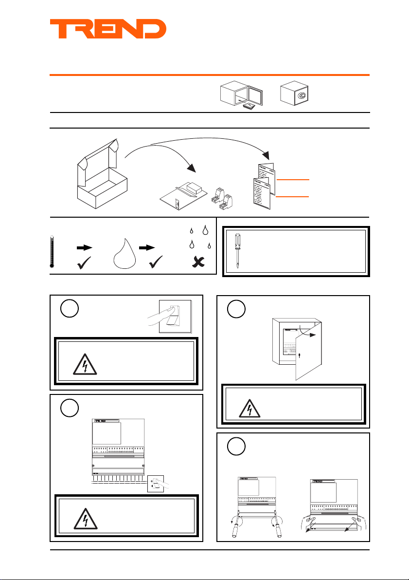
Important: Retain these instructions
SHEET 1: Installation
Unpacking
Installation Instructions
S Cards
SCVO, SCVI, SCCI, SCTI,
SCDI, S Cards Installation
Instructions TG103127
1
1
2
Sheet 1
Sheet 2
Storage
-10 °C
Installation
+50 °C
Switch Off
1
WARNING: To prevent damage to the
Isolate I/O
2
WARNING: The connecting leads may
0
H O
2
IQ241/242, or S Cards the
controller must be powered
down during the installation.
be connected to supplies.
Isolate before touching.
90 %RH
It is recommended that the installation
should comply with the HSE
Memorandum of Guidance on
Electricity at Work Regulations 1989.
O
I
a undo screws
Open Panel
3
WARNING: Opening the panel may
4
expose dangerous voltages.
417-IEC-5036
Remove ENCLS/CMTRAY
Cover
If ENCLS/CMTRAY fitted
b lift off cover
SCVO, SCVI, SCCI, SCTI, SCDI S Cards Installation Instructions TG103127 Issue 2/A 22/5/03 1 - 1
Page 2
SCVO, SCVI, SCCI, SCTI, SCDI Installation Instructions
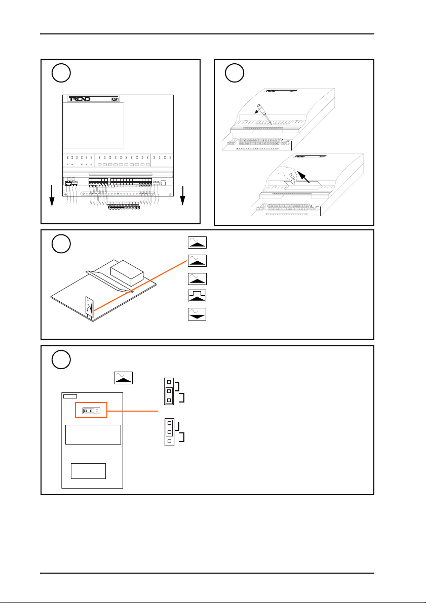
Installation (continued)
Disconnect Appropriate I/O
5
Identify S Card
7
Set Loop/Ext Link
8
if SCCI
I
Open S Card Flap
6
I
analogue current input S card (SCCI)
V
analogue voltage input S card (SCVI)
T
thermistor input S card (SCTI)
digital input S card (SCDI)
V
analogue voltage output S card (SCVO)
Note each S card provides 2 channels of the same type.
LOOP
Link set for external power supply
EXT
1 - 2
LOOP
SCVO, SCVI, SCCI, SCTI, SCDI S Cards Installation Instructions TG103127 Issue 2/A 22/5/03
Link set for controller power
EXT
Page 3
Installation Instructions -Fixing SCVO, SCVI, SCCI, SCTI, SCDI
I
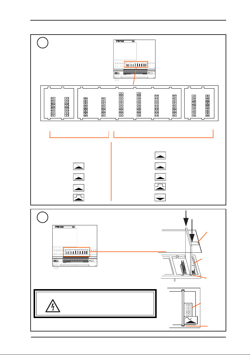
Installation (continued)
Identify S Card Slot
9
13 15 17 19 21 23 25 27 29 31
13 15 17 19 21 23 25 27 29 31
Channel
Numbers
13 15 17 19 21 23 25 27 29 31
14 16 18 20 22 24 26 28 30 32
Note that the IQ242 has 4 SCTI
Input Cards only
cards pre-fitted in these slots (i.e.
8 thermistor input channels)
Permitted
S Cards
I
SCCI
V
SCVI
T
SCTI
SCDI
Fit S Cards
10
13 15 17 19 21 23 25 27 29 31
Note that only input cards should be fitted in
the first 4 slots (from the left)
WARNING: In some card positions spare pins are present
on the board. Ensure cards are properly
connected to correct pins; failure to do so may
cause damage to S card and main board.
Input or Output Cards
Permitted
S Cards
I
V
T
V
SCCI
SCVI
SCTI
SCDI
SCVO
S card type
connector
slot
connector
Ensure card is pushed fully home
SCVO, SCVI, SCCI, SCTI, SCDI S Cards Installation Instructions TG103127 Issue 2/A 22/5/03
slot
1 - 3
Page 4

SCVO, SCVI, SCCI, SCTI, SCDI Installation Instructions
Installation (continued)
Replace S Card Flap
11
12
Identify I/O Connectors
8
1
I1
2 345
d ig ita l in pu ts
7
1 0 1 1
6
9
1 7
1 5 1 6
1 9
1 8
2 2 2 3
2 0 2 1
I2 1
I2 0
S 8
S 9
L 2 0
1 4
1 2
1 3
I1 2 I1 3
a n a lo g u e in p ut s
S 1
stupnilatigidnitliuB sdracSylnotupnI sdracStuptuOrotupnI stuptuoegatlovnitliuB
C1C2C3C4C5C6C7C8C9C01C11C
lanretxE
ecnerefer
I1I2I3I4I5I6I7I8I9I01I11I
latigiD
tupnI
rosneS
revirD
tuptuO
lennahc
1C3C5C7C9C11C13C15C17C19C21C23C25C27C29C31C33C35C37C39
2C4C6C8C10C12C14C16C18C20C22C24C26C28C30C32C34C36C38C40
C31C41C51C61C71C81C91C02C12C22C32C42C52C62C72C82C92C03C13C23C33C43C53C63C73C83C93C
21
I31I41I51I61I71I81I91I02I12I22I32I42I52I62I72I82I92I03I13I
21
S1S2S3S4S5S6S7S8S9S01S11S21S31S41S51S61S71S81S91S
L02L91L81L71L61L51L41L31L21L11L01L9L8L7L6L5L4L3L2L
Note sensors start at
channel 13
These channels already fitted
on IQ242 (thermistor inputs)
! # % '
! # % ' ! # % ' !
" $ & " $ & ! !
" $ &
TX RX
8
7
14
10 11
1
2 345
6
9
12
13S120 21
I1
digit al in puts
I12 I13
anal ogue inp uts
LAN
1C3C5C7C9C11C13C15C17C19C21C23C25C27C29C31C33C35C37C39
2C4C6C8C10C12C14C16C18C20C22C24C26C28C30C32C34C36C38C40
2 9 3 0 31
3 3
3 5 3 6
3 2
3 4
I3 2
S 1 5
L 9
L 8
2 5
2 4
2 6 2 7 2 8
!! !# ! % !'
!" !$ ! & "
171819
22 23
33
15 16
29 30 313435 36
32
242526 27 28
I32
I20
I21
S15
S8
S9
L20
L9
L8
AUX
C
24v
C
+-+
3 7
3 9
3 8
a n al o gu e o u tp u ts
04
23
02
1
C
C
Note outputs have reverse numbering
8
40
373839
ana logu e o utpu ts
L1
-
4 0
L 1
1 - 4
13
Continue Installation
S cards Installation
2
Instructions,
TG103127, Sheet 2
SCVO, SCVI, SCCI, SCTI, SCDI S Cards Installation Instructions TG103127 Issue 2/A 22/5/03
Page 5

SCVO, SCVI, SCCI, SCTI, SCDI
I
SHEET 2: Installation (continued)
Installation Instructions
S Cards
1
S
Install S Card
S cards Installation
Instructions,
TG103127, Sheet 1
Connect Inputs
2
IN
C
Earth bar
V
IN
C
Sensor Thermistor Inputs
(Channels 13 to 32 only)
0 V
Earth bar
14
15
Trend TP/1/1/22/HF/500 (Belden 8761) cable recommended for all inputs
Terminal size 0.5 to 2.5 mm
Digital Inputs
(Channels 13 to 32 only)
Sensor Voltage Inputs
(Channels 13 to 32 only)
V (0 to 10 V)
2
T
IN
C
Earth bar
Sensor Current Inputs
(Channels 13 to 32 only)
→ I (0 to 20 mA)
SIG
S
see step 8 for internal/external power link
SCVO, SCVI, SCCI, SCTI, SCDI S Cards Installation Instructions TG103127 Issue 2/A 22/5/03 2 - 1
I
IN
C
Earth bar
Sensor External Powered Current Inputs
(Channels 13 to 32 only)
→ I (0 to 20 mA)
SIG
S
see step 8 for internal/external power link
IN
C
Earth bar
Page 6

SCVO, SCVI, SCCI, SCTI, SCDI Installation Instructions
Installation (continued)
Connect Outputs
16
Trend TP/1/1/22/HF/500 (Belden 8761) cable recommended for voltage outputs
Terminal size 0.5 to 2.5 mm
Analogue Voltage Outputs (Channels 21 to 32 only)
maximum current 20 mA per channel
2
V
OUT
C
Earth bar
WARNING: If external relays are fitted, the wires may
Switch On
17
0 to 10 Vdc
0 Vdc
be connected to hazardous voltages.
Disconnect power before attempting any
wiring.
18
O
I
(power)
a
(green)
Load
Check Controller
Additional Relay Modules
IQ24x
SRMV =
2SRM =
2RM =
3RM =
6RM =
b
Relay
Module
x 1
x 2
x 2
x 3
x 6
(watchdog)
(red)
nRM
(RLM/HLM)
(HCM/TRM)
2 - 2
Check supply
SCVO, SCVI, SCCI, SCTI, SCDI S Cards Installation Instructions TG103127 Issue 2/A 22/5/03
IQ Faulty
Page 7

Installation Instructions -Fixing SCVO, SCVI, SCCI, SCTI, SCDI
O
I
Installation (continued)
19
20
Test Inputs
a
Switch off
Switch on
c
O
I
Test Outputs
Switch off
a
b
Connect Inputs
O
I
d
I Q 2 4 1 / 2 4 2
S
I Q 2 4 1 / 2 4 2
∆T = X
(yellow)
Connect Outputs
b
O
I
Switch on
c
SCVO, SCVI, SCCI, SCTI, SCDI S Cards Installation Instructions TG103127 Issue 2/A 22/5/03
d
I Q 2 4 1 / 2 4 2
S
(yellow)
2 - 3
Page 8

SCVO, SCVI, SCCI, SCTI, SCDI Installation Instructions
O
I
Installation (continued)
Replace ENCLS/CMTRAY Cover
21
if ENCLS/CMTRAY fitted
I Q 2 4 1
Reconnect Supply to I/O
23
Close Panel
22
I Q 2 4 1
Trend Control Systems Ltd reserves the right to revise this publication from time to time and make changes to the content hereof without
obligation to notify any person of such revisions or changes.
Trend Control Systems Ltd P.O. Box 34 Horsham Sussex RH12 2YF Telephone 01403 211888 Fax 01403 241608 www.trend-controls.com
2 - 4
SCVO, SCVI, SCCI, SCTI, SCDI S Cards Installation Instructions TG103127 Issue 2/A 22/5/03
 Loading...