

Page 1
Data Sheet
RJ, RN
Thyristor Controllers
RJ, RN Thyristor Controllers
Thyristor Controllers (solid state relays) provide a means of varying the voltage for electrically resistive loads, typically electric
heating elements.The RN controllers are not suitable for switching lamps due to light flicker.
srotsiryhTdnerTnoitpircseDgnisuoHnoitcelesedoM*
E05V32P1JRrotsiryhtA05caV032elop1JRseY
E05V84P1JRrotsiryhtA05c
03V84F2NRrotsiryht)eloprepA51(A03caV084elop22NHRdexiF
05V84F2NRrotsiryht)eloprepA52(A05caV084
* RJ controllers have 5 operating modes (Phase Angle, Distributed Full Cycle and Burst Control, at 1, 3, and 10 s), whereas RN
controllers use a Full Cycle fixed operating mode.
All Trend RJ, RN solid state thyristor relays have the following specification:
Control input :0 to 10 Vdc, 0.1 mA at 10 Vdc
Control supply
RJ :20 to 28 Vac/dc; 18 mA at 24 Vdc, 23 mA at 24 Vac
RN :12 to 32 Vdc or 21 to 27 Vac; 30 mA at 32 Vdc or 27 Vac
Current ratings :depend on ambient temperature, nominal 30, 50 A ratings are at 25 °C (RJ), 30 °C (RN) ambient.
Voltage ratings
230 V :90 to 265 Vac (RJ), 85 to 265 Vac (RN)
480 V :200 to 550 Vac (RJ), 190 to 530 Vac (RN)
aV084elop1JRseY
elop22NHRdexiF
Documents Attached:
Carlo Gavazzi RJ1P data sheet (27/06/2006)
Carlo Gavazzi RN.F data sheet (30/09/2005)
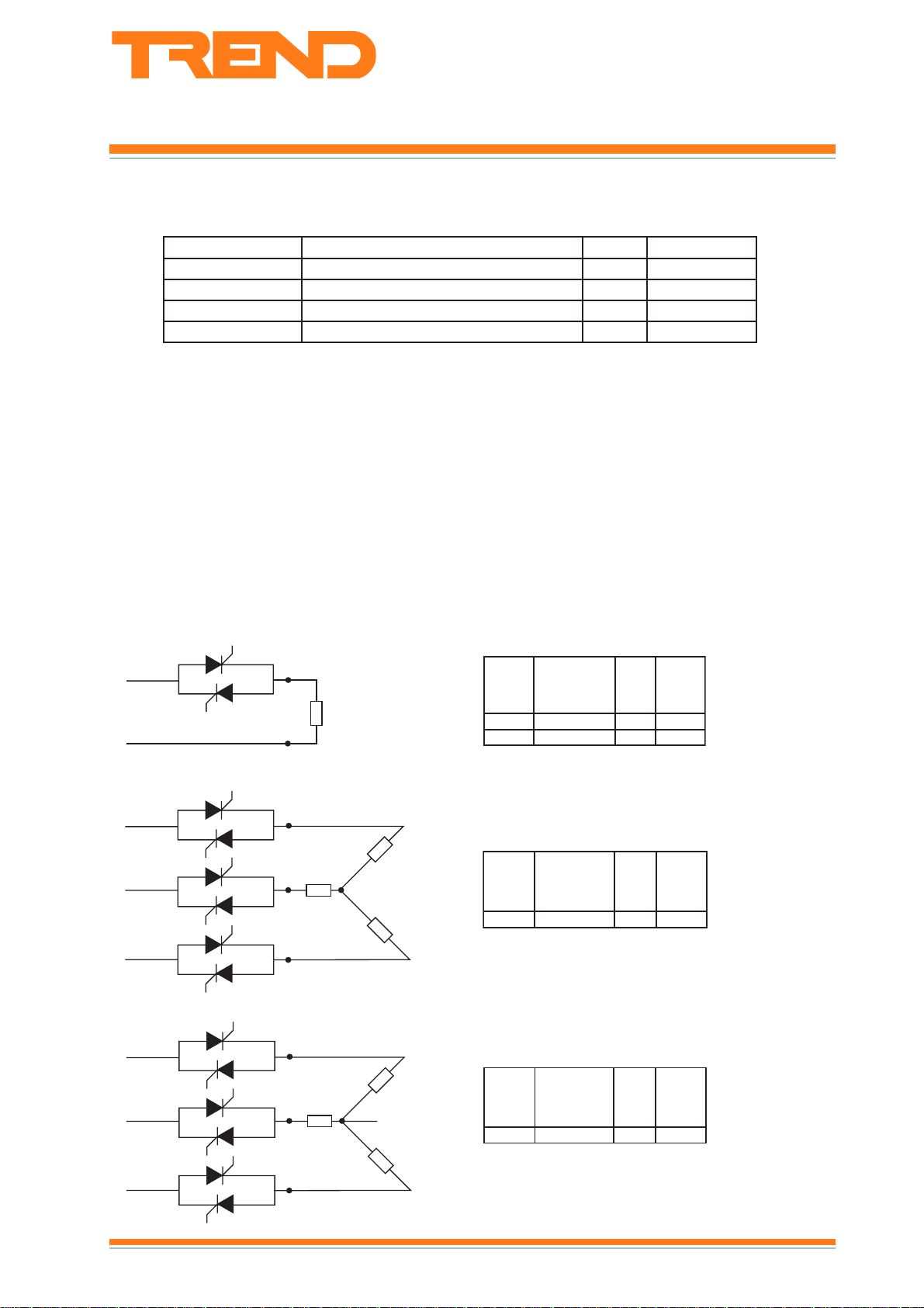
Applications:
1 2 wire phase to phase or phase to neutral
LINE
LOAD
NEUTRAL
2 3 wire 3 phase floating star load
LINE
LINE
LINE
(resistive)
LOAD
LOAD
(all loads resistive)
LOAD
ytitnauQ
deriuqer
1E05V32P1JR0521
1E05V84P1JR0521
ytitnauQ
deriuqer
3E05V84P1JR0563
epyT
epyT
IxaM
)A(
IxaM
)A(
xaM
caV032
daol
)Wk(
xaM
caV514
daol
)Wk(
3 4 wire 3 phase with star point to neutral
LINE
LINE
LINE
(all loads resistive)
LOAD
LOAD
NEUTRAL
LOAD
RJ, RN Thyristor Controllers Data Sheet TA200697Issue 2/A 10/01/07
ytitnauQ
deriuqer
3E05V84P1JR0563
epyT
IxaM
)A(
xaM
caV514
daol
)Wk(
1
Page 2
RJ, RN Data Sheet
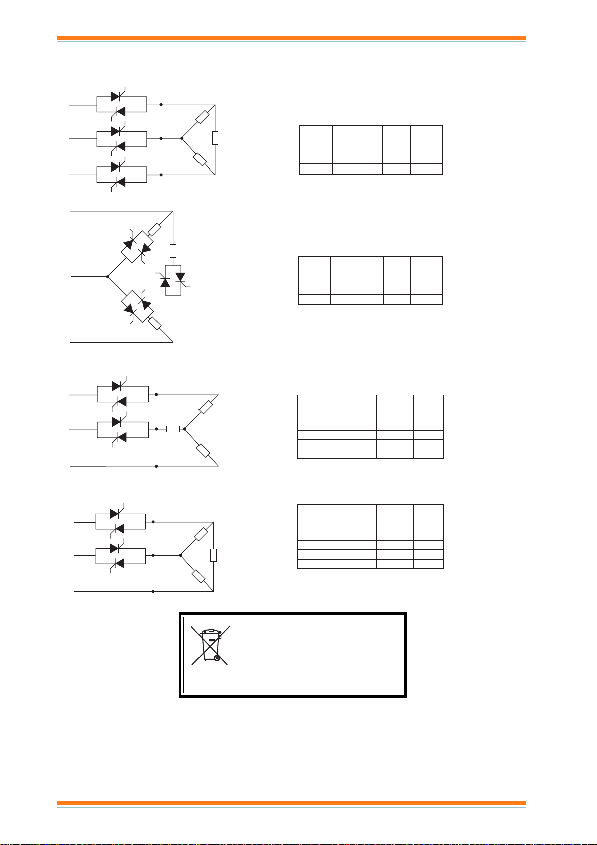
Applications (continued)
4 3 wire 3 phase closed delta load
LINE
LINE
LINE
(all loads resistive)
5 3 wire 3 phase open delta load
LINE
LOAD
LOAD
LINE
LOAD
LINE
(all loads resistive)
6 3 wire 3 phase star load
2 phases controlled (burst fire only)
LINE
LINE
LINE
LOAD
(all loads resistive)
LOAD
LOAD
LOAD
LOAD
LOAD
ytitnauQ
deriuqer
epyT
IxaM
)A(
3E05V84P1JR0563
ytitnauQ
deriuqer
epyT
IxaM
)A(
3E05V84P1JR053.26
ytitnauQ
deriuqer
epyT
IxaM
)A(
2E05V84P1JR0563
103V84F2NR518.01
105V84F2NR5281
xaM
caV514
daol
)Wk(
xaM
caV514
daol
)Wk(
xaM
caV514
daol
)Wk(
7 3 wire 3 phase delta load
2 phases controlled (burst fire only)
LINE
LINE
LINE
(all loads resistive)
LOAD
LOAD
LOAD
ytitnauQ
deriuqer
epyT
)A(
2E05V84P1JR0563
103V84F2NR518.01
105V84F2NR5281
xaM
IxaM
caV514
daol
)Wk(
DISPOSAL
WEEE Directive :
At the end of their useful life the packaging and
product should be disposed of by a suitable
recycling centre.
Do not dispose of with normal household waste.
Do not burn.
Manufactured for and on behalf of the Environmental and Combustion Controls Division of Honeywell Technologies Sàrl, Ecublens, Route
du Bois 37,Switzerland by its Authorized Representative, Trend Control Systems Limited.
Trend Control Systems Limited reserves the right to revise this publication from time to time and make changes to the content
hereof without obligation to notify any person of such revisions or changes.
Trend Control Systems Limited
P.O. Box 34, Horsham, West Sussex, RH12 2YF, UK. Tel:+44 (0)1403 211888 Fax:+44 (0)1403 241608 www.trend-controls.com
Trend Control Systems USA
6670 185th Avenue NE, Redmond, Washington 98052, USA. Tel: (425)897-3900, Fax: (425)869-8445 www.trend-controls.com
2
RJ, RN Thyristor Controllers Data Sheet TA200697Issue 2/A 10/01/07
Page 3
Rated operational Non-rep. voltage Control input Supply voltage Rated operational
voltage current (50 A)
230VACrms 650Vp 0 - 10VDC 24VAC/DC RJ1P23V50E
4 - 20mA RJ1P23I50E
480VACrms 1200Vp 0 - 10VDC 24VAC/DC RJ1P48V50E
4 - 20mA RJ1P48I50E
600VACrms 1200Vp 0 - 10VDC 24VAC/DC RJ1P60V50E
4 - 20mA RJ1P60I50E
Solid State Relay
Number of poles
Switching mode (Proportional)
Rated operational voltage
Control input type
Rated operational current
Terminal layout
Specifications are subject to change without notice (27.06.2006) 1
• AC semiconductor contactor
• Multi-function - 5 selectable modes of operation:
Phase Angle, Distributed Full Cycle and Burst Control
(1, 3 and 10s)
• Direct copper bonding (DCB) technology
• LED-indication for control and load status
• Operational ratings up to 50 AACrms and 600 VAC
• 4-20mA or 0-10V control input
• Built-in varistor
• Non-repetitive voltage: Up to 1200Vp
• Opto-isolation > 4000VACrms
• Cage clamp terminals
• IP20 protection
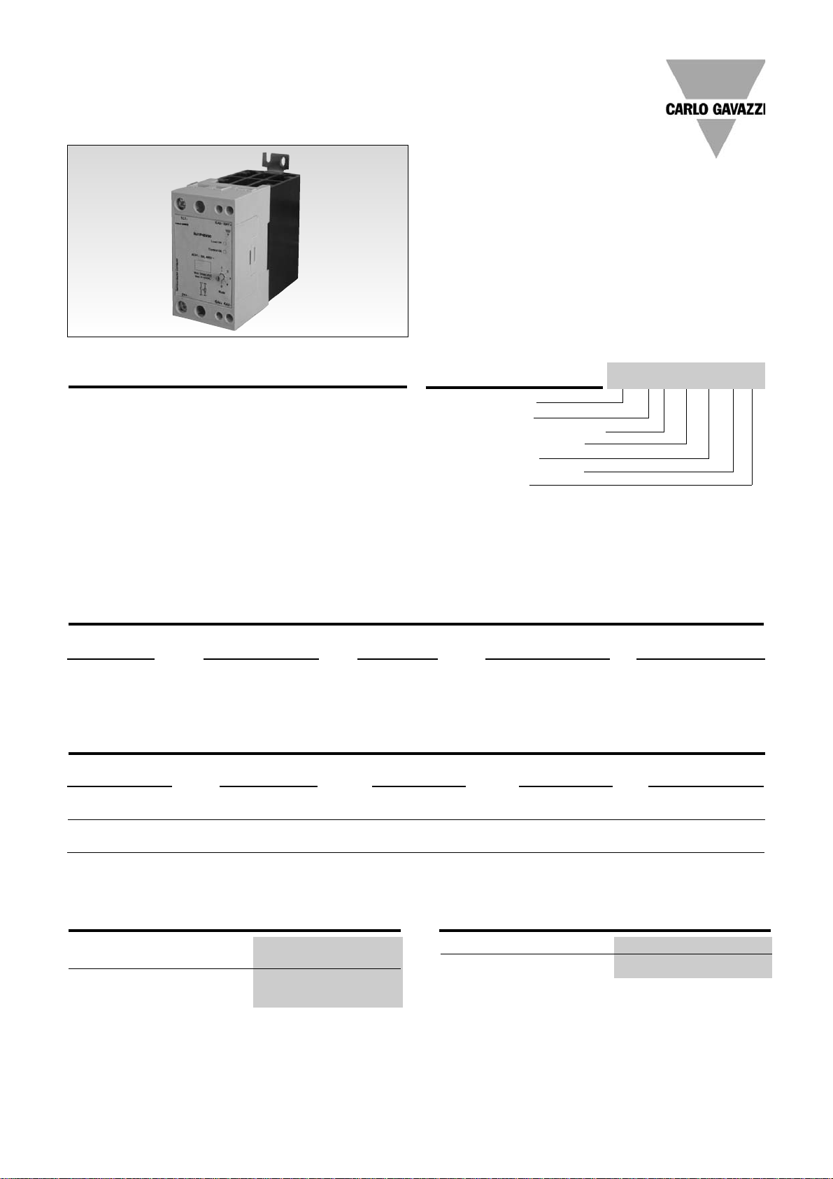
Product Description
Ordering Key
The Solitron Midi Analog
Switching is a single-phase
SSR that provides proportional
output power in relation to the
control signal level applied.
This microprocessor-based
device provides for 5 different
switching modes integrated
into one package. A selector
switch on the front of the
device is used for the selection
of the preferred mode of operation, i.e., either Phase Angle,
Distributed Full Cycle or Burst
Control. This multi-function
selection makes this device
ideal for the control of a variety
of loads, including heaters and
lamps. The control signal can
be either 4 - 20mA or 0 10VDC. 4mA or 0V correspond
to zero output power, whilst
20mA or 10VDC correspond to
full output power.
The product is ready to mount
on DIN-rail or chassis and
comes with integral heatsink.
Solid State Relays
SOLITRON MIDI Multi-Function Analog Switching
Type RJ1P
Type Selection
Switching Rated operational Control Rated operational Terminal
mode voltage input current layout
P: Proportional 23: 230VACrms V: 0 - 10VDC 50: 50AACrms E: Contactor
Output 48: 480VACrms I: 4 - 20mA
60: 600VACrms
Selection Guide
RJ 1 P 48 V 50 E
Thermal Specifications
Operating temperature -20 to +60ºC (-4 to +140 ˚F)
Storage temperature -40 to +100ºC (-40 to +212 ˚F)
Insulation
Rated insulation voltage
Input to output ≥ 4000 VACrms
Output to case ≥ 4000 VACrms
Page 4

RJ1P23... RJ1P48... RJ1P60...
Operational voltage range 90 to 265VAC 200 to 550VAC 410 to 660VAC
Non-rep. peak voltage 650V
p
1200V
p
1200V
p
Operational frequency range 45 to 65Hz 45 to 65Hz 45 to 65Hz
Output power 0 to 99% 0 to 99% 0 to 99%
Power factor ≥ 0.9 @ 230VACrms ≥ 0.9 @ 480VACrms ≥ 0.9 @ 600VACrms
Load status indication Red LED Red LED Red LED
Output power resolution
MODE 1 Phase Angle 1/300 @ 50Hz, 1/300 @ 60Hz
MODE 2 Full Cycle 1/64 @ 50Hz, 1/64 @ 60Hz
MODE 3 Burst with 1s period 1/50 @ 50Hz, 1/60 @ 60Hz
MODE 4 Burst with 3s period 1/150 @ 50Hz, 1/180 @ 60Hz
MODE 5 Burst with 10s period 1/500 @ 50Hz, 1/600 @ 60Hz
Approvals UL, cUL
CE-marking
Ye s
RJ1P..I...
Current controlled input
Control current range 4 - 20mA
Max. allowable input current 50mA
Pick up current 4.2mA
Drop out current 3.9mA
Control status indication Green LED
Reverse polarity protected Yes
Voltage drop 10VDC @ 20mA
RJ1P..V...
Voltage controlled input
Supply voltage range, Vss 20 - 28VAC/DC
Supply current 18mA @ 24VDC
23mA @ 24VAC
Control voltage range, Vcc 0 - 10VDC
Control input current 0.1mA @ 10VDC
Reverse polarity protected Yes
Pick up voltage 0.5VDC
Drop out voltage 0.05VDC
Control status indication Green LED
2 Specifications are subject to change without notice (27.06.2006)
RJ1P
Input Specifications
General Specifications
Weight Approx. 430 g
Housing material PBT Flame retardant
Control terminal cable size
Min 1 x 0.5 mm
2
(1 x AWG20)
Max 1 x 4.0 mm
2
(1 x AWG12) or
2 x 2.5 mm
2
(2 x AWG14)
Mounting torque max. 0.6 Nm Posidriv 0 bit
Control terminal screw M3
Power terminal cable size
Min 1 x 4 mm
2
(1 x AWG12)
Max 1 x 25 mm
2
(1 x AWG3) or
2 x 10 mm
2
(2 x AWG6)
Mounting torque max. 2.5 Nm Posidriv 2 bit
Power terminal screw M5
Housing Specifications
Output Specifications
Rated operational current
AC51 @Ta=25ºC 50AACrms
Min. operational current 150mAACrms
Rep. overload current t=1 s
(Tj init.=25°C) < 200AACrms
Non-rep. surge current t=10 ms
(Tj init.=25°C) 1900A
p
Off-state leakage current,
@ rated voltage and frequency < 3 mArms
I2t for fusing t=10 ms 18000A2s
On-state voltage drop @
rated current 1.6Vrms
Critical dV/dt off-state 1000V/µs
Page 5

Example: RJ1P48I50E Example: RJ1P48V50E
~
~
-
+
LOAD
4 - 20mA
2T1
1L1 5A3
3A1
4A26A4
~
~
LOAD
+
10VDC
2T1
1L1 5A3
3A1
4A26A4
+
0V24VDC/AC
-
0V
-
Specifications are subject to change without notice (27.06.2006) 3
RJ1P
Connection Examples
3A1 - 5A3: Control input current
3A1 - 5A3: Control input voltage, Vcc
4A2 - 6A4: Supply input voltage, Vss
LED INDICATION
The top Red LED indicates the
load status. It goes ON whenever the load is activated. The
Green LED gives indication of
the status of the control input.
Upon application of control
current (for the RJ1P..I...) to
terminals A1-A3, the Green
LED will be dimly lit, with its
intensity increasing with an
increase in control current.
For the RJ1P..V..., the Green
LED will be ON (flickering)
upon application of the supply
voltage to terminals A2 - A4.
Once a control voltage is
applied to terminals A1 - A3,
the Green LED will be fully ON,
if greater than a threshold voltage (approx. 0.5V). Note that
the first time the device (voltage control version) is to be
activated, the mains voltage
has to be present for the
Green LED to indicate the
control status.
Terminal Layout
Mode Selection
Operation
MODE
Transfer characteristics
Control Control Output
Current (mA) Voltage (VDC) Power (%)
400
8 2.5 25
12 5 50
16 7.5 75
20 10 99
Output power as a function of control input
MODE 1 Phase Angle Switching
MODE 2 Distributed Control
MODE 3 Burst Switching (1 sec. period)
MODE 4 Burst Switching (3 sec. period)
MODE 5 Burst Switching (10 sec. period)
MODE 1: The Phase Angle
switching mode works in
accordance with the phase
angle control principle, i.e. the
output switching point in the
AC sine wave depends on the
signal level applied at the
input. The relay switches off
everytime the output current
crosses zero.
MODE 2: The Distributed
mode provides a number of
full cycles, evenly distributed
over a fixed period of 1.28s @
50Hz (1.07s @ 60Hz), depending on the control input.
MODE 3, 4, 5: The Burst
Switching mode generates a
number of full cycles, depending on the control input over
fixed periods of 1s, 3s or 10s
for MODES 3, 4 and 5 respectively.
Modes 2, 3, 4 and 5 use the
zero switching principle, thus
ensuring a reduced level of
radiated and wire-conducted
noise. The Distributed and
Burst Switching modes are not
recommended for light control
due to light-flickering.
Note: For the RJ1P..V..., it is possible to have the ground terminals of the supply and control power supplies used commoned. In the case, this common
ground is connected either to terminal A2 or terminal A3. This is only applicable when a 24 VDC supply voltage is used. There should be no external direct
link from terminal A2 to Terminal A3.
Page 6

4 Specifications are subject to change without notice (27.06.2006)
Derating vs. Spacing Curves
RJ1P
Derating Curve
Dissipation Curve
Load Current
(AACrms)
Surrounding temp. (Deg. C)
20 30 40 50 60
20
30
40
50
60
10
0
0102030405060
AACrms
W
10
20
30
40
50
0
50A
Note: Based on 100% output power
Surrounding temp. (˚C)
Note: Based on 100% output power
22.5mm
10.0mm
6.0mm
3.0mm
0.0mm
Load Current (AACrms)
Page 7

Specifications are subject to change without notice (27.06.2006) 5
Dimensions
Functional Diagram
IC
A2 (-)
A4 (+)
A3 (-)
A1 (+)
Supply
input
Control
input
1 period = 64 cycles
1 period = 1s, 3s or 10s
RJ1P
Note: A2, A4 used only for voltage control version
MODE 1
Phase Angle
MODE 2
Distributed Full Cycle
MODE 3, 4, 5
Burst 1s, 3s, 10s
All dimensions in mm.
Page 8

Specifications are subject to change without notice (30.09.2005) 1
• AC solid state relay, 1- and 2-poles
• Analog switching for resistive loads (heating)
• 4-20 mA or 0-10 V controls
• Rated operational current: 1-pole : 30A and 50A
2-pole : 2 x15A and 2 x 25A
• Rated operational voltage up to 480 VAC
• LED-indication for normal operation and alarm status
• IP 20 protection
• DIN-rail mountable
Product Description
Ordering Key
RN 1 F 40 V 30
The analog switching relay provides a number of full cycles,
evenly distributed over a fixed
period, depending of the control input. The input of 4-20 mA
or 0-10 VDC respectively,
corresponds to zero and full
output within a period of 1.28 s
@ 50 Hz (1.07 s @ 60 Hz). This
principle makes the transfer
characteristics fully linear. The
principle operates with zero
switching, thus ensuring a
reduced level of radiated and
wire conducted noise. The 2pole type has alarm LED indication by loss of master
phase. The analogue Full
Cycle Switching is not recommended for light control due
to light-flickering.
Solid State Relay
Number of poles
Switching type
Rated operational voltage
Control signal
Rated operational current
Solid State Relays
Analog Full Cycle Switching
Type RN.F
Type Selection, 1-Pole
Rated Control Control Rated operational current
operational voltage input supply 30 A 50 A
120 VAC 4-20 mA 7-10 VDC RN 1F12I30 RN 1F12I50
0-10 VDC 12-32 VDC, 24 VAC RN 1F12V30 RN 1F12V50
230 VAC 4-20 mA 7-10 VDC RN 1F23I30 RN 1F23I50
0-10 VDC 12-32 VDC, 24 VAC RN 1F23V30 RN 1F23V50
480 VAC 4-20 mA 7-10 VDC RN 1F48I30 RN 1F48I50
0-10 VDC 12-32 VDC, 24 VAC RN 1F48V30 RN 1F48V50
Type Selection, 2-Pole
Rated Control Control Rated operational current
operational voltage input supply 30 A Total (2 x 15A) 50 A Total (2 x 25A)
120 VAC 4-20 mA 7-10 VDC RN 2F12I30 RN 2F12I50
0-10 VDC 12-32 VDC, 24 VAC RN 2F12V30 RN 2F12V50
230 VAC 4-20 mA 7-10 VDC RN 2F23I30 RN 2F23I50
0-10 VDC 12-32 VDC, 24 VAC RN 2F23V30 RN 2F23V50
480 VAC 4-20 mA 7-10 VDC RN 2F48I30 RN 2F48I50
0-10 VDC 12-32 VDC, 24 VAC RN 2F48V30 RN 2F48V50
Page 9

2 Specifications are subject to change without notice (30.09.2005)
Thermal Specifications
RN.F..30 RN.F..50
Operational temperature -20° to +70°C (-4° to +158°F) -20° to +70°C (-4° to +158°F)
Storage temperature -20° to +100°C (-4° to +212°F) -20° to +100°C (-4° to +212°F)
Junction temperature < 125°C (257°F) < 125°C (257°F)
R
th
junction to ambient (AC load) 2.8 K/W 1.7 K/W
General Specifications
RN.F12... RN.F23... RN.F48...
Operational voltage range 85 to 140 VAC 85 to 265 VAC 190 to 530 VAC
Non-rep. peak voltage 800 V
p
800 V
p
1000 V
p
Varistor voltage 275 VAC 275 VAC 510 VAC
Zero voltage turn-on < 10 V < 10 V < 20 V
Operational frequency range 45 to 65 Hz 45 to 65 Hz 45 to 65 Hz
Power factor at rated voltage ≥ 0.9 ≥ 0.9 ≥ 0.9
Average output power 0 to 100% 0 to 100% 0 to 100%
Output power resolution 1/64 of 100% 1/64 of 100% 1/64 of 100%
Approvals UL, cUL, CSA UL, cUL, CSA UL, cUL, CSA
CE-marking Yes Yes Yes
Norms fulfilled EN 60947-1 Low-voltage switchgear and control gear. Part 1- General Rules.
EN 61000-6-1 Generic Immunity Standard. Residential, Commercial & Light Industry Environment
EN 61000-6-2 Generic Immunity Standard. Industrial Environment
Output Specifications
RN.F..30 RN.F..50
Rated operational current
RN1F.. AC51 @Ta=30°C 30 A 50 A
“ @Ta=40°C 30 A 50 A
“ @Ta=50°C 23 A 38 A
“ @Ta=60°C 20 A 30 A
RN2F.. AC51 @Ta=30°C 30 A total sum (2 x 15A) 50 A total sum (2 x 25A)
“ @Ta=40°C 30 A total sum (2 x 15A) 50 A total sum (2 x 25A)
“ @Ta=50°C 23 A total sum (2 x 11.5A) 38 A total sum (2 x 19A)
“ @Ta=60°C 20 A total sum (2 x 10A) 30 A total sum (2 x 15A)
Zero crossing detection Yes Yes
Min. operational current (per pole) 500 mA 500 mA
Rep. overload current t=1 s
(Tj init.=25°C) 55 A (rms) 125 A (rms)
Non-rep. surge current t=10 ms
(Tj init.=25°C) < 300 A
p
< 580 A
p
Off-state leakage current,
@ rated voltage and frequency
(Tj.=125°C, max.) < 6 mA < 6 mA
I2t for fusing t=1 to 10 ms 450 A2s 1680 A2s
Critical dV/dt off-state 500 V/µs 500 V/µs
RN 1F
Input Specifications
RN.F..I..
Current controlled input
Control current range 4 - 20 mA
Allowable input current 50 mA
Reverse polarity protected Yes
Voltage drop 10 VDC @ 20 mA
RN.F..V..
Voltage controlled input
Supply voltage range 21 - 27 VAC, 12 - 32 VDC
Supply current 30 mA @ 24 VAC/32 VDC
Control voltage range 0 - 10 V
Control input current 0.1 mA @ 10 VDC
Page 10

Specifications are subject to change without notice (30.09.2005) 3
Insulation
Rated impulse withstand voltage
Input to output 4000 V
imp
Rated impulse withstand voltage
Output to heatsink 4000 V
imp
Dimensions
Dimensions (H x W x D)
RN..30 120 x 45 x 110 mm
RN..50 120 x 90 x 110 mm
Housing Specifications
Mounting DIN-rail 35 mm
Weight with RHN1 470 g
Weight with RHN2 780 g
Housing material Noryl SEI, GFN1, Black
LED window material PC Lexan 141R
Base plate Aluminium, nickel plated
Potting compound Polyurethane, Casco Nobel
Terminals
Screw with captive wire clamp
Control terminals nominal 4 mm2 or 2 x 2.5 mm
2
AWG 12 or 2 x AWG 14
Min. 0.5 mm
2
, AWG 20
Mounting torque max. 0.6 Nm
Power terminals nominal 10 mm
2
or 2 x 6 mm
2
AWG 6 or 2 x AWG 10
Min. 1 mm
2
, AWG 16
Mounting torque max. 2.0 Nm
Heatsink compound used Electrolube HTS
Environment Specifications
Humidity max. 95%, no condensation
RN 1F
Dimensions
4
120
45
33,7
103
71,6
37
30
20
70
60
4
120
93
72
45
89
103
71,6
37
20
70
30
60
Note: all dimensions in mm
Wiring Diagrams
L
1A1A2
T
1
4 - 20 mA
+
Current Control
_
L
1
A1A
2
T
1
A3A
4
0 - 10 VDC
+
Voltage Control
_
Control
Supply
L1A1A
2
T
1
4 - 20 mA
+
Current Control
_
L
1
A
1A2
T1A3A
4
0 - 10 VDC
+
Voltage Control
_
Control
Supply
L
2
L
2
T
2
T
2
Single-pole relay
Double-pole relay
Note: all dimensions in mm
RN..30
RN..50
Page 11

4 Specifications are subject to change without notice (30.09.2005)
VAC / VDC
A
2
X
X
+
_
A3A
4
L
1
T
1
C/V
L
2
T
2
X
X
A
1
Functional Diagrams
Applications
Terminal Layout
1-pole RN.. 2-pole RN..
L
1
A
1
A
2
A
1
L
2
L
1
T
1
A
3
T
1
A
4
A
3
T
2
RN 1F
A
2
A
4
Double pole relay in 3-phase application
Star and delta application (Economy Switching only)
L
1
L
2
L
3
2-pole current controlled input
Master
Slave (2-pole version)
Single and double pole relay application
Line-Neutral
L
1
L
2
N
VAC/VDC (A3, A4only used for voltage control)
control
signal
 Loading...