

Page 1
Important: Retain these instructions
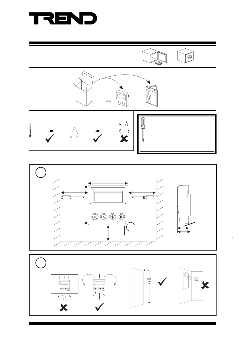
UNPACKING
Installation Instructions
RD-IQL
Room Display
RD-IQL Installation
Instructions TG200576
STORING
-10 °C
+14 °F
+50 °C
+122 °F
INSTALLATION
Dimensions
1
Requirements
2
a
0 %RH
H O
2
150 mm (6”)
500 mm (1’6”)
It is recommended that the installation
95 %RH
should comply with the HSE
Memorandum of Guidance on Electricity
at Work Regulations 1989.
For USA, install equipement in
accordance with National Electric Code.
For use with IQLVAV, IQL11+, 13+, 15+ controllers only
90 mm (3.54”)
150 mm (6”)
90 mm (3.54”)
minimum
b
30 mm (1.18”)
> 50 cm (1’6”)
c
25 mm
(0.98”)
RD-IQL Installation Instructions TG200576 Issue 1/G 16/01/07
1.5 m (5’)
1
Page 2
RD-IQL Installation Instructions
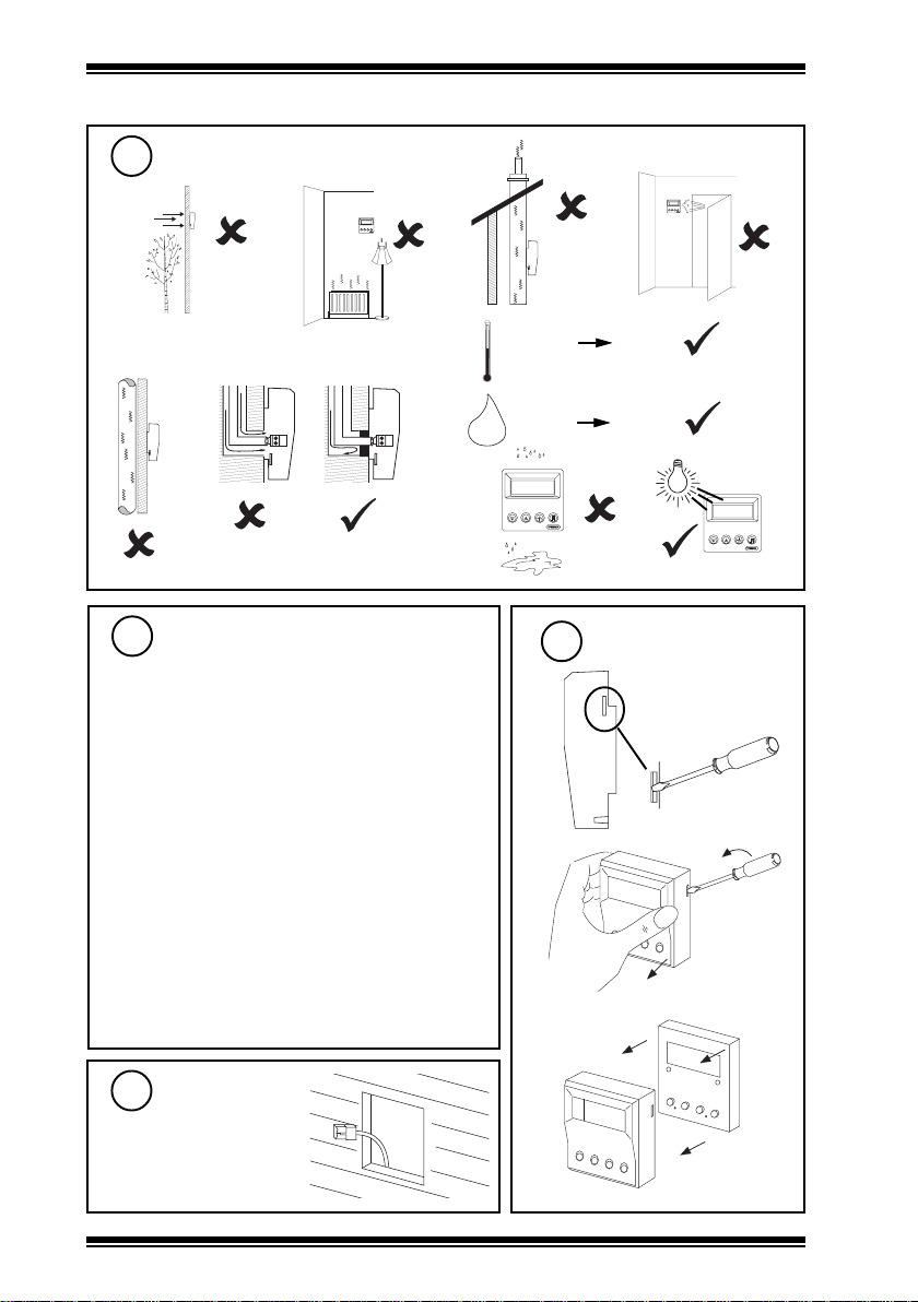
INSTALLATION (continued)
Requirements (continued)
2
d
e
f
g
j
h
i
k
Check IQL+, IQLVAV Controller
3
Compatibility
Compatible with IQLVAV, IQL11+, 13+, 15+ only
IQLs must have standard strategies or standard item
allocations as follows:
S9, S10, S1, S2, S3 (IQLVAV, IQL11+, 13+, 15+)
I9 (IQL11+, 13+, 15+), I12 (IQLVAV)
S11, S7 (IQL13+, 15+)
IQLVAV, IQL11+ can use RD/IQL/K, /KOS
IQL13+, 15+ can use RD/IQL/K, /KOS, /KOSF
The RD’s potentiometer must be used (if potentiometer
required); a direct connected potentiometer may not be
used. A direct connected temperature sensor may be
used rather than the RD’s.
RD-IQL/K precludes use of PIR/pushbutton inputs and
(on IQLVAV only) alarm contact input. A separate fan
speed switch may be used (IQL13+, 15+).
RD-IQL/KOS as RD-IQL/K except pushbutton is provided.
RD-IQL/KOSF as RD-IQL/KOS except Fan speed switch
is provided (for IQL13+, 15+). A separate Fan Speed
switch may be used (rather than the RD’s).
-10 °C
+14 °F
0 %RH
H O
2
+40 °C
+122 ° F
90 %RH
l
Remove Front Panel
4
a
b
c
Route Cable
5
2
RD-IQL Installation Instructions TG200576 Issue 1/G 16/01/07
Page 3
Installation Instructions RD-IQL
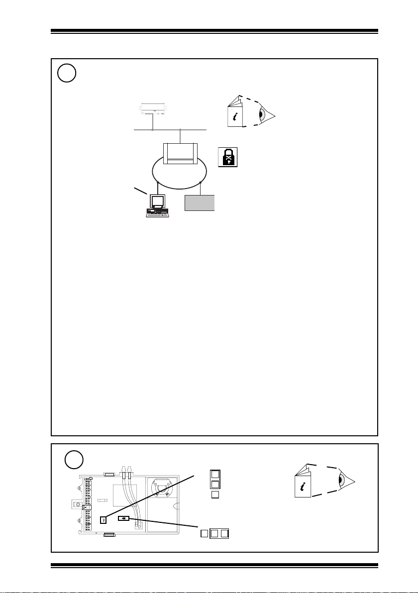
INSTALLATION (continued)
Configure IQLVAV/IQL+ for use with RD
6
Connect Trend Tool for Text Communications
a
IQL
Lon
See IQLTool2
See PowerTool Manual
TE200163
See Wupdn Manual
TE200162
LINC
SET v5.1
IQLTool2
IQ
b
Configure parameters
The following parameters must be set up (their configuration is facilitated by IQLTool2
‘Configure for RD-IQL’ feature):
Local Space Temp Type S9(Y=6) (use RD) - IQL11+, 13+, 15+, IQLVAV
Local SP Adjust Type S10(Y=6) (use RD) - IQL11+, 13+, 15+, IQLVAV
Local Fan Speed Type S11(Y=6) (use RD) - IQL13+, 15+
These settings are facilitated by IQLTool2.
If it is required to use a separate temperature sensor, leave Local Space Temp Type at default,
S9(Y=1).
If it is required to use a separate fan speed switch, leave Local Fan Speed Type at default, S11(Y=3).
The following parameters should be set up if they have been changed from default:
Note that these parameters are in the standard strategies; equivalent parameters may have to be
changed in non-standard strategies
Window Mode W5(S=O) (not window mode, default) - IQL11+
PIR Pb Select W6(S=O) (Pushbutton selected, default) - IQL11+, 13+, 15+
Remote Fan Spd K7(V=4) (auto, default) - IQL13+, 15+
The following command must be given:
R(z=1) :This writes changes to permanent flash memory, and causes the IQL/IQLVAV to start using
the new settings
Note that a PIN may be required to make
changes. If the PIN has been forgotten the
users should contact their supplier (installers
contact Trend Technical Support) quoting the
generator number and neuron id (both from Address
module) whereupon a default PIN will be supplied.
This will only work for three attempts at entering the
PIN. After the default PIN is entered a new PIN
should be set up and remembered.
Configure IQLVAV link (IQLVAV only)
7
RD
I
5
A
RD-IQL Installation Instructions TG200576 Issue 1/G 16/01/07
J6
J5
Set link J5
S
Check link J6
IQLVAV Installation
Instructions
e.g. IQLVAV/xxx ../VAV
TG200704
3
Page 4
RD-IQL Installation Instructions
S P E N G
1 2 3 4
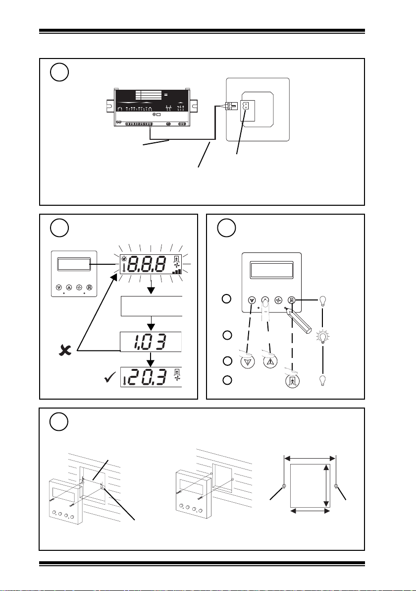
INSTALLATION (continued)
Connect to IQL+ Controller
8
L AN
O /S
S tr at eg y
N ID
D O2
D O1
D O4
D O3
C OM
C OM
24 V
24 V
~
~
Digital (TBus) input
First digital input:
IN3 for IQL11+,
IN4 for IQL13+ and IQL15+
IN5 for IQLVAV
Note that IQL+/IQLVAV may be connected while powered; if not power up IQL+/IQLVAV.
D O5 IN 2
: : : : :
IN 1
C OM
I Q
L
+
L O N
2 4 V a c
IN 3
RD-IQL (rear view)
polarity independent
maximum distance 30m (33 yds)
Check Start Up Reset
9
1 2 3 4
S P E N G
every 7 s:
communications
Firmware version
failure
11
Mount Unit
standard UK electric back box
60 mm
2 off
M3.5 x 35 mm screws provided
10
° F
° C
A U T O
Engineer Temperature Offset
if required to offset sensor value
a
default=0
ENG + 2
b
or
c
° C
A U T O
d
or panel
60 mm
50 mm
M3.5
screw
46 mm
M3.5
screw
4
RD-IQL Installation Instructions TG200576 Issue 1/G 16/01/07
Page 5

Installation Instructions RD-IQL
O n
O f f
° C
° F
INSTALLATION (continued)
12
Select Temperature Units if Temperature Units OK
Display Local Temperature if Local Temperature Display OK
Use Local Thermistor Local Thermistor Use OK
Display Fan State
[Switch off for option /K, /KOS]
Display Occupation State
[Switch off for option /K]
Engineer Display
if required
1 2 3 4
ENG + 3
a
b
c
d
e
f
g
h
i
WARNING: Do NOT switch off ‘Use Local Thermistor’
(leave at default = On). Switching ‘Use Local
!
Thermistor’ off will cause IQL to cease controlling
if Fan State Display OK
j
k
l
if Occupation State Display OK
m
n
o
S P E N G
,
°C °F
,
,
Off
Off
default = °C
default = On
On
,
On
default =
default = On
O n
O n
O f f
default = On
Normal Mode
RD-IQL Installation Instructions TG200576 Issue 1/G 16/01/07
p
5
Page 6

RD-IQL Installation Instructions
INSTALLATION (continued)
13
14
Restore Defaults
if required
Restore Defaults
Defaults as shown in step 12
Normal Mode
Replace Front Panel
ENG + 1 + 4
a
b
c
1 2 3 4
S P E N G
15
6
Adjust Contrast
° F
° C
RD-IQL Installation Instructions TG200576 Issue 1/G 16/01/07
° F
° C
Page 7
Installation Instructions RD-IQL
° C
° C
° C
INSTALLATION (continued)
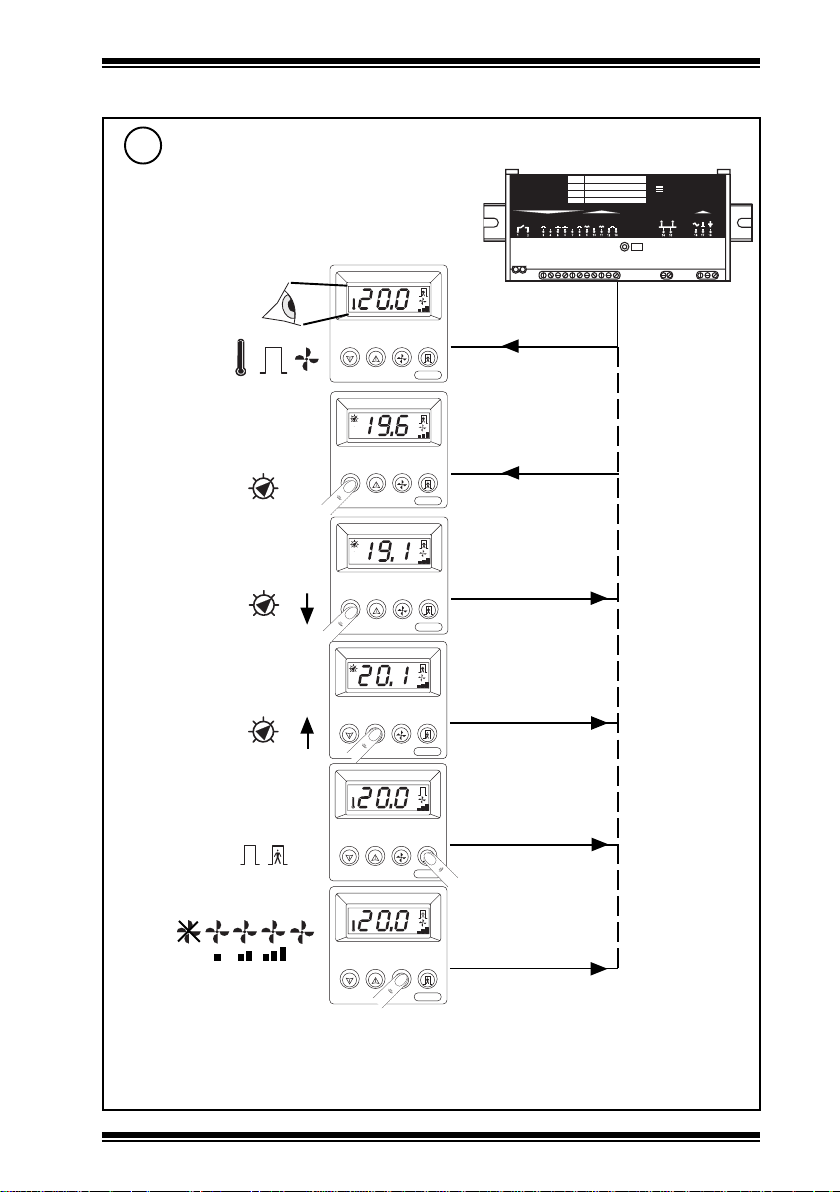
16
Check System
Dependent on option
/K, /KOS, /KOSF
a
/K, /KOS, /KOSF
b
/K, /KOS, /KOSF
c
/K, /KOS, /KOSF
d
/K, /KOS, /KOSF
° C
S9 °C (°F) Temp
S3 Occupation, S7 Fan
Speed
S2 °C (°F) Setpoint
S2 °C (°F)
S2 °C (°F)
L A N
O / S
S t ra t e g y
: : : : :
N I D
IN 1
D O 5 IN 2
D O 2
D O 1
D O 4
D O 3
C O M
C O M
C O M
2 4V
2 4V
~
~
I Q
L
+
L O N
IN 3
2 4 V a c
e*
/KOS, /KOSF
f
/KOSF only
AUTO
* Note that when using an IQL standard strategy, in step ‘e’ the RD can override the occupation
on, but not off. The strategy will define when the occupation switches off.
RD-IQL Installation Instructions TG200576 Issue 1/G 16/01/07
° C
S3 Occupation
° C
S7 Fan Speed
7
Page 8

RD-IQL Installation Instructions
DISPOSAL
WEEE Directive :
At the end of their useful life the packaging
and product should be disposed of by a
Do not dispose of with normal household waste.
Do not burn.
suitable recycling centre.
Manufactured for and on behalf of the Environmental and Combustion Controls Division of Honeywell Technologies Sàrl, Ecublens, Route
du Bois 37,Switzerland by its Authorized Representative, Trend Control Systems Limited.
Trend Control Systems Limited reserves the right to revise this publication from time to time and make changes to the content hereof
without obligation to notify any person of such revisions or changes.
Trend Control Systems Limited
P.O. Box 34, Horsham, West Sussex, RH12 2YF, UK. Tel:+44 (0)1403 21888 Fax:+44 (0)1403 241608 www.trend-controls.com
Trend Control Systems USA
6670 185th Avenue NE, Redmond, Washington 98052, USA. Tel: (425)897-3900, Fax: (425)869-8445 www.trend-controls.com
8
RD-IQL Installation Instructions TG200576 Issue 1/G 16/01/07
 Loading...