

Page 1
Important: Retain these instructions
L+
L+
L-
L-
OU T
L
N
IN
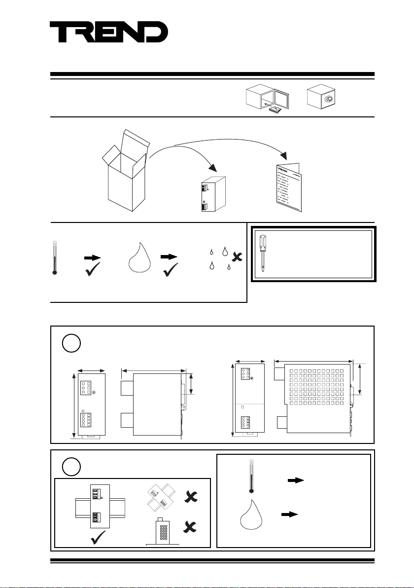
1.1 Unpacking
Installation Instructions
PSR230/24
Power Supplies
L
IN
N
L+
L+
OU T
LL-
1.2 Storage
-25 °C
Extended storage: Equipment containing capacitors should be connected to
the input supply for at least 5 minutes every two years.
+85 °C 30
H O
2
85 %RH
1.3 Installation
Dimensions
1
All dimensions in mm
PSR230/24-1.3
40
L
N
95
L +
L +
O U T
L L -
Requirements
2
a
L
N
90
IN
PSR230/24-2.5, PSR230/24-5
51 mm (PSR230/24-2.5)
67 mm (PSR230/24-5)
50
130
b
It is recommended that the
installation should comply with
the HSE Memorandum of
Guidance on Electricity at Work
Regulations 1989.
L
IN
N
O K
L +
L +
O U T
L L -
-10 °C
PSR230/24
Installation
Instructions
TG200566
145
55
+70 °C
L +
L +
O U T
L L -
H O
2
30 85 %RH
non-condensing
Protection: IP20
PSR230/24 Installation Instructions TG200566 Issue 1/B 06/04/06
1
Page 2
PSR230/24 Installation Instructions
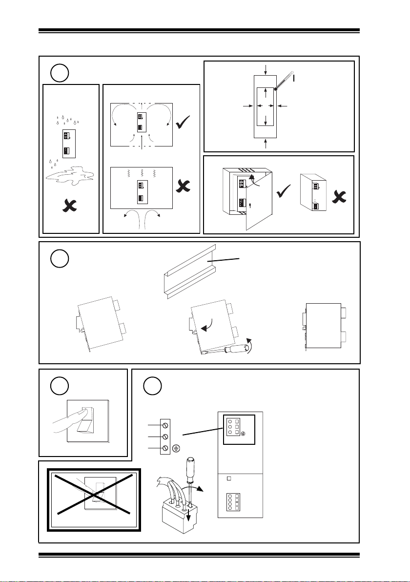
1.3 Installation (continued)
Requirements (continued)
2
c
L
N
IN
L+
L+
O UT
LL-
Mount on DIN Rail
3
d
a
e
70 mm
15
mm
L
N
IN
L+
L+
OU T
LL-
70 mm
> +180 °C
15
mm
f
L
N
L
N
IN
L+
L+
OU T
LL-
IN
L+
L+
O UT
L-
L-
35 mm DIN rail (DIN EN 50022)
b
c
L
IN
N
DC
AD J.
L+
L+
OU T
LL-
Switch Off
4
DO NOT SWITCH ON
2
Connect Input Supply
5
230 Vac (100 to 240 Vac) 50 to 60 Hz
O
I
O
230 Vac
L
N
L
N
L
N
E
O K
I
Cable 0.08 mm
L +
L +
L L -
2
PSU Consumption =
I N
0.3 A PSR230/24-1.3
0.6 A PSR230/24-2.5
1.2 A PSR230/24-5
Inrush Current =
<15 A PSR230/24-1.3
<50 A PSR230/24-2.5
O U T
<50 A PSR230/24-5
to 2.5 mm2 (28 to 14 AWG) stripped
length 8 to 9 mm (0.33”)
PSR230/24 Installation Instructions TG200566 Issue 1/B 06/04/06
Page 3

Installation Instructions PSR230/24
L +
L +
L L -
O U T
L
N
O K
I N
L+
L+
LL-
OUT
L
N
OK
IN
V
1.3 Installation (continued)
Connect Output Supply
6
24 Vdc
L
N
I N
L +
L +
L L -
+
Load
I max = 1.3 A PSR230/24-1.3
2.5 A PSR230/24-2.5
5 A PSR230/24-5
7
9
O K
L +
L +
O U T
L L -
Switch On
Set Voltage
if required
Cable 0.08 mm2 to 2.5 mm2 (28 to 14 AWG) stripped
length 8 to 9 mm (0.33”)
Rate 3 x I max
Check LED
8
if PSR230/24-2.5, PSR230/24-5
(not PSR230/24-1.3)
O
DC (green)
check steps
I
5, 6 & 7
above
PSR230/24 Installation Instructions TG200566 Issue 1/B 06/04/06
Load
3
Page 4

PSR230/24 Installation Instructions
1.3 Installation (continued)
Close Panel
10
L
N
IN
L +
L +
O U T
L -
L -
1.4 Disposal
WEEE Directive :
At the end of their useful life the packaging
and product should be disposed of via a
Do not dispose of with normal household waste.
Do not burn.
suitable recycling centre.
11
Test System
L
IN
N
OK
L+
L+
OUT
LL-
V
24 Vdc
Load
Manufactured for and on behalf of the Environmental and Combustion Controls Division of Honeywell Technologies Sàrl, Ecublens, Route
du Bois 37,Switzerland by its Authorized Representative, Trend Control Systems Limited.
Trend Control Systems Limited reserves the right to revise this publication from time to time and make changes to the content hereof
without obligation to notify any person of such revisions or changes.
Trend Control Systems Limited
P.O. Box 34, Horsham, West Sussex, RH12 2YF, UK. Tel:+44 (0)1403 21888 Fax:+44 (0)1403 241608 www.trend-controls.com
Trend Control Systems USA
6670 185th Avenue NE, Redmond, Washington 98052, USA. Tel: (425)869-8400, Fax: (425)869-8445 www.trend-controls.com
4
PSR230/24 Installation Instructions TG200566 Issue 1/B 06/04/06
 Loading...