

Page 1
Installation Instructions - Fixing
PNC2
Printer Node Controller
Important: Retain these instructions
CONTENTS
1.1 Unpacking 1 - 1
1.2 Storage 1 - 1
SHEET 1: Installation Instructions - Fixing
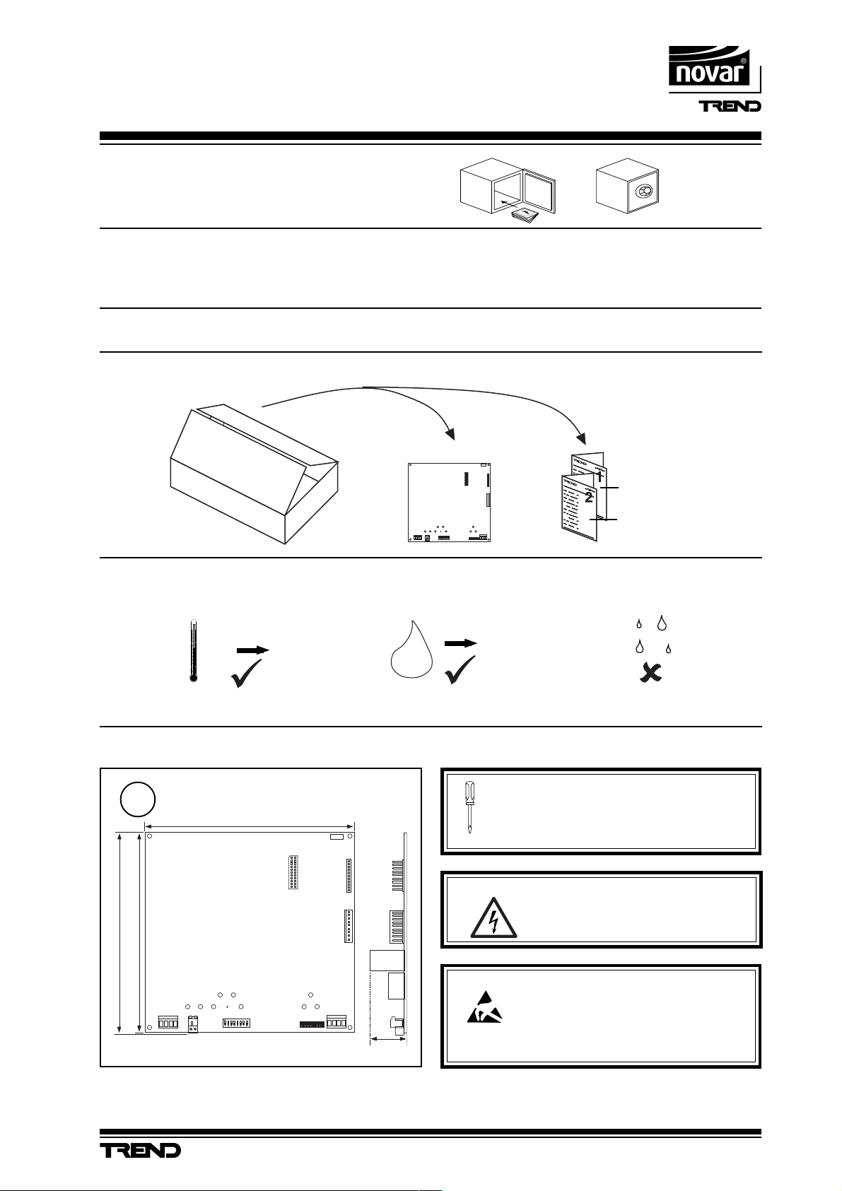
1.1 Unpacking
1.2 Storing
-10 °C
+50 °C
H O
1.3 Installation Instructions - Fixing 1 - 1
2.1 Installation Instructions - Configuration 2 - 1
2.2 Connecting to LRM 2 - 3
1
Installation Instructions,
E T1
J1 7
J1 6
D ev B
J1 5
D ev A
J8
0
2
J7
La n A
95 %RH
TG200264
Sheet 1, Fixing
Sheet 2, Configuration
1.3 Installation -Fixing
Dimensions
1
160 mm
151 mm
154 mm
J 8
PNC2 Printer Node Controller Installation Instructions TG200264 Issue 1/D 22/07/04
It is recommended that the installation should
comply with the HSE Memorandum of Guidance
E T 1
J 1 7
J 1 6
D e v B
J 1 5
D e v A
J 7
L a n A
33 mm
on Electricity at Work Regulations 1989.
WARNING: Opening the panel may expose
dangerous voltages.
417-IEC-5036
Caution: The PNC2 contains static-sensitive devices.
Suitable anti-static precautions should be
taken throughout this operation to prevent
damage to the unit.
BS EN100015/1 Basic Specification: protection of
electostatic sensitive devices.
1 - 1
Page 2
PNC2 Installation Instructions - Fixing
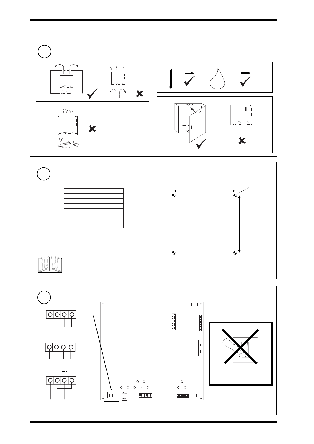
1.3 Installation - Fixing (continued)
Requirements
2
a
ET1
J16
Dev B
J15
Dev A
J7
J8
Lan A
ET1
J16
Dev B
J15
Dev A
J7
J8
Lan A
b
0 °C +45 °C
d
c
ET 1
J1 6
De v B
J1 5
De v A
J7
J8
La n A
Mount the Node
3
The PNC2 can be fitted into enclosures and controllers as shown in the table below:
BBTEN/BTEN
+201/+101QI
+111QI
+131QI
152QI
052QI
242/142QI
332/132QI
* PNC2 board fits with 3 screws in normal node position or
fits in NDP position (if no NDP). Must use NDP position if
RDS fitted.
9
9
9
9
9*
9*
9
9
0 %RH 95 %RH
H O
2
ET 1
J1 7
ET 1
J17
J16
De v B
J15
De v A
J7
J8
Lan A
J8
151 mm
J1 6
De v B
J1 5
De v A
J7
La n A
4 off 4 mm
141 mm
See appropriate enclosure/controller
installation instructions for more details about
node installation.
Connecting Power
4
~ ~ 0V
24 Vdc
+24 V 0V
~ ~ 0V
18-0-18 Vac
18 18 0
~ ~ 0V
18 Vac
(isolated)
18 Vac
terminal size 0.5 to 2.5 mm
PNC2 consumption <=5 VA
E T 1
J 1 7
J 1 6
D e v B
J 1 5
0
D e v A
I
DO NOT APPLY
POWER
J 8
2
J 7
L a n A
1 - 2
PNC2 Printer Node Controller Installation Instructions TG200264 Issue 1/D 22/07/04
Page 3
Installation Instructions - Fixing PNC2
1.3 Installation - Fixing (continued)
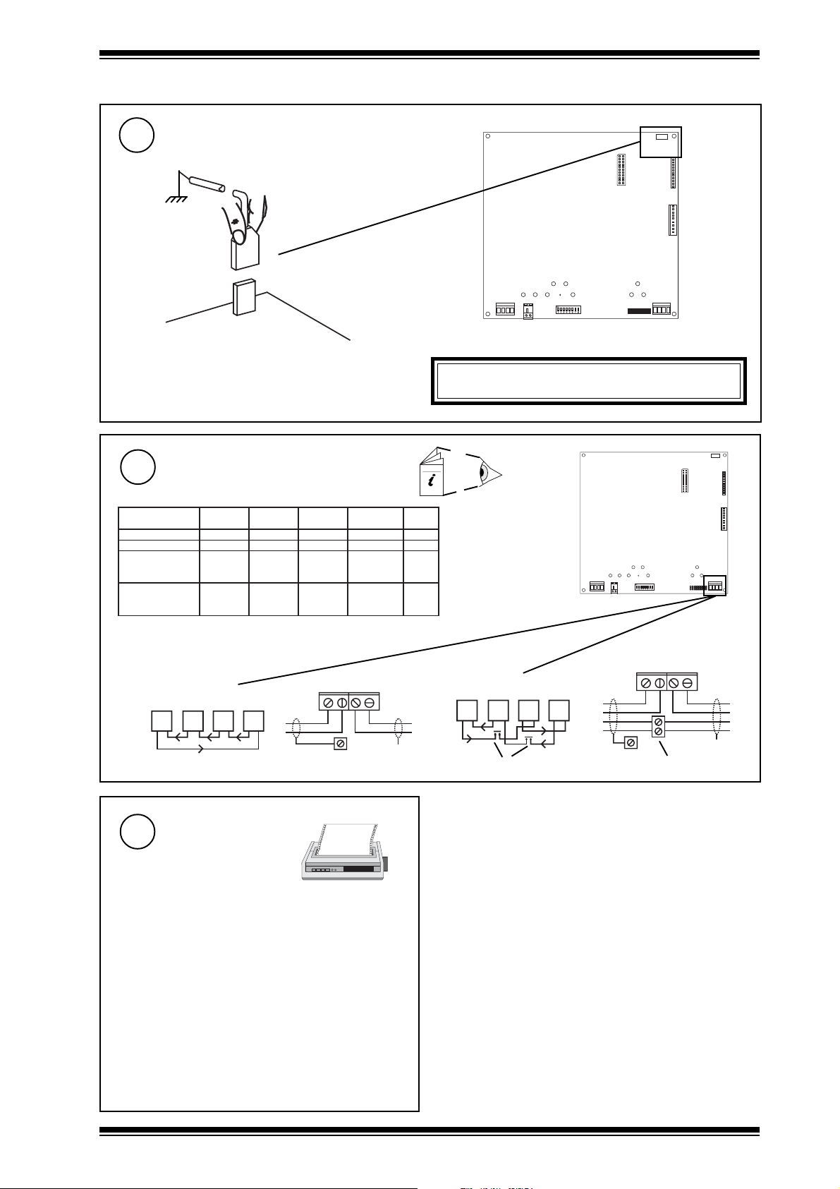
Connecting Earth
5
Connect Network (Lan A)
6
Network Engineering Manual, 92-1735
elbaCduab2k1duab8k4duab6k9duab2k91
2819nedleBm0001m0001m0001m0072
7029nedleBm0001m0001m0001m0052
metsysQI
/FH/22/1/1/PT
)1678nedleB(
metsysQI
)3278nedleB(
terminal size 0.5 to 2.5 mm
m0001m0001m007m0532
002
m0001m0001m005m0524
002/FH/22/2/2/PT
E T 1
J 1 7
J 8
J 1 6
D e v B
J 1 5
D e v A
J 7
L a n A
WARNING: This apparatus must be earthed
E T 1
J 1 7
J 1 6
D e v B
fo.oN
seriW
J 8
2
J 1 5
D e v A
J 7
L a n A
Polarity independent
L A N A
R +
T -
T + R -
e a r t h b u s
R
T
Select Printer
7
2 wire
R
T
R
T
R
R
T
R
(Device B - RS232)
Printer must:
• Be able to accept Epson type control codes
• Have an RS232 serial interface with following settings:
Baud Rate: 19k2, 9k6, 4k8 or 1k2
Serial/Parallel: Serial
Comms type: either 8 bits no parity
Auto Line Feed: On
The PNC2 must have its baud rate and comms type set
accordingly, see PNC2 installation instructions Sheet 2:
Configuration steps 5 and 6
or 7 bits odd parity
L A N A
4 wire
T -
R +
e a r t h b u s
T + R -
T
T
R
R
X
additional terminals
R
T
R
T
T
T
R
T
T
R
R
R
T
T
X
additional terminals
PNC2 Printer Node Controller Installation Instructions TG200264 Issue 1/D 22/07/04
1 - 3
Page 4

PNC2 Installation Instructions - Fixing
1.3 Installation - Fixing (continued)
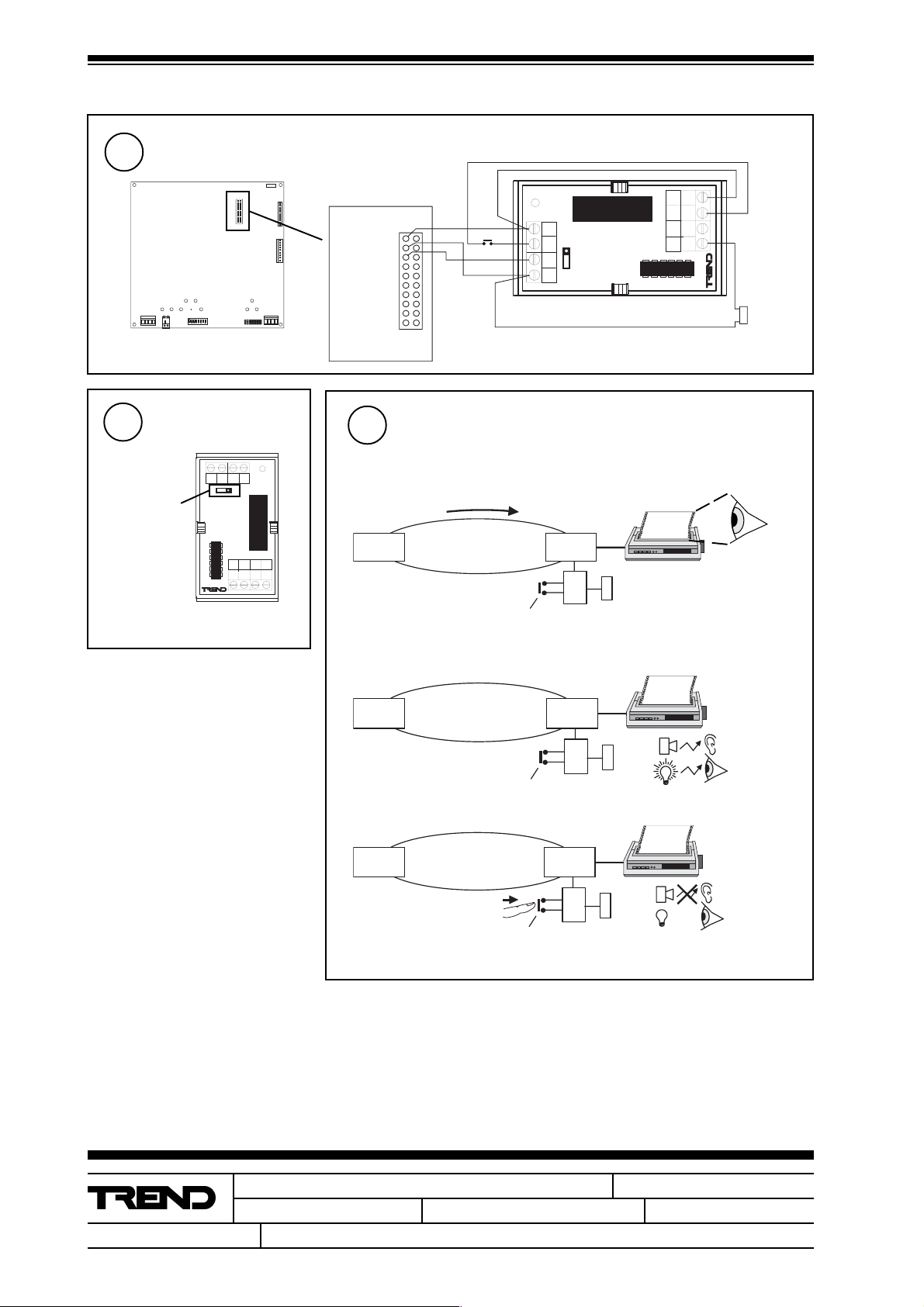
Connect to Printer
8
(Device B - RS232)
E T 1
J 1 7
J 1 6
1
J16
D e v B
Dev B
J 1 5
J 8
J 7
L a n A
10 Way, Molex, Female
links between pins 2-4, 3-5
D e v A
1
Connect Auxiliary Supply Output
9
E T 1
J 1 7
J 1 6
D e v B
J 1 5
D e v A
AUX
cables not supplied with unit
CABLE/EJ100179A001
Ensure correct polarity
24 V
25 Way D type male to male
cable, pins 3, 7, 20 connected
straight through
25 Way, D type, Male
25 Way, D type, Female
Close Panel/Box
10
25 Way, D type, Male
E T 1
J1 7
J1 6
D e v B
J1 5
D e v A
PNC2
24 V
J 7
L a n A
I max = 150
mA
J 8
terminal size 0.5
to 2.5 mm
11
2
Configure/Commission
2
PNC2 Installation Instructions - Sheet 2: Configuration
J8
J7
L an A
1 - 4
PNC2 Printer Node Controller Installation Instructions TG200264 Issue 1/D 22/07/04
Page 5

Installation Instructions - Configuration
J 7
E T 1
J 1 6
D e v B
J 1 5
D e v A
J 8
L a n A
J 1 7
PNC2
Printer Node Controller
SHEET 2: Installation Instructions - Configuration
2.1 Installation - Configuration
Fix Unit
1
PNC2 Installation
Instructions - Sheet 1:
Fixing
1
Set the Network Address
(Lan A)
3
e.g.
O N
A D D R E S S
Address = 2+16+64= 82
NOT SET
D U M B
N O R M
SET
2
Address = D
= D
/
Switch off and
open panel/
covers
O
I
J 8
= D
J8
PNC2
E T 1
J 1 7
= D
/
WARNING: Opening the panel may expose
dangerous voltages.
417-IEC-5036
ET 1
J17
J16
De v B
J15
De v A
J7
Lan A
Caution: The PNC2 contains static sensitive devices.
Suitable anti-static precautions should be
taken throughout this operation to prevent
damage to the unit.
BS EN100015/1 Basic Specification: protection of
electostatic sensitive devices.
2
Set Network Baud Rate
(Baud A)
4
J 1 6
D e v B
J 1 5
D e v A
J 7
L a n A
B a u d B B a u d A
e.g 9k6
move link to
set baud rate
J 8
Network Baud Rate = R1
= R1
= R1
J 1 7
= R1
E T 1
J 1 6
D e v B
J 1 5
D e v A
J 7
L a n A
= D
address
1, 4 to 9, 11 to 114
0, 2, 3, 10 or >119
/
= R1
B a u d B B a u d A
Set Device B connector (RS232) to Printer Baud Rate
5
(Baud B)
move link to
set baud rate
B a u d B B a u d A
e.g 19k2
B a u d B B a u d A
PNC2 Printer Node Controller Installation Instructions TG200264 Issue 1/D 22/07/04
Device B (J16) to printer Baud Rate = R2
= R2
= R2
PNC2
2 - 1
Page 6

PNC2 Installation Instructions - Configuration
O
I
J 7
E T 1
J 1 6
D e v B
J 1 5
D e v A
J 8
L a n A
J 1 7
2.1 Installation - Configuration (continued)
Set Dumb/Normal switch to Printer Comms Type
6
e.g.
O N
7
A D D R E S S
Switch On
D U M B
N O R M
Dumb
Sets Printer Comms Type to:
8 bits no parity
Norm
Sets Printer Comms Type to:
7 bits odd parity
Check Node Controller
8
E T 1
J 1 7
J 1 6
D e v B
J 1 5
D e v A
a PWR ON
(green)
Check supply
J 8
J 7
L a n A
0
I
b W/DOG
(red)
PNC2 Faulty
Check Network
9
a RXA
(yellow)
E T 1
J 1 7
J 1 6
D e v B
J 1 5
D e v A
J 8
J 7
L a n A
b TXA
(yellow)
c OKA
?
(green)
P N C 2
P N C 2
?
Network Address Invalid
0, 2, 3 or >119
✘
L A N A
OKA
PNC2
PNC2 Faulty
T - T + R - R +
2 - 2
L A N A
T - T + R - R +
PNC2 Printer Node Controller Installation Instructions TG200264 Issue 1/D 22/07/04
OKA
Check network cabling for
short circuits with a
multimeter (NOT Megger)
Check baud rate
Power up other nodes until
faulty node is found
(OK ). Correct fault.
Page 7

Installation Instructions - Configuration PNC2
2.1 Installation - Configuration (continued)
Set up printer
11
10
Close panel/covers
ET 1
J1 7
J1 6
De v B
J1 5
De v A
J8
J7
La n A
Set printer RS232 serial interface as follows:
Baud rate set as step 5 above (1k2, 4k8, 9k6, or 19k2)
Comms type set as step 6 above
either 8 bits no parity
or 7 bits odd parity
Auto Line Feed: On
Configure Alarm Language
12
if required
The PNC2 will automatically set its alarm language to that of the other nodes on the local Lan if possible (otherwise stays in English). It may be changed
if required:
PNC2
Recommend use of PowerTool
or Wupdn
IQ Configuration Manual 90-1533
PNC2 Data Sheet TA200263
PowerTool Manual TE200163
Wupdn Manual TE200162
Set language by R(P=x)
where x defines language as follows:
x=0 English, =1 Spanish, =2 Finnish, =3 Swedish, =4 Norwegian, =5 Danish, =6 German, =7 Italian, =8 Portuguese, =9 French.
Note that if the PNC2 is reset by power up or on change of address or baud rate, the PNC2 will automatically set its language
13
Check System
IQ
! alarm
Lan
! alarm
PNC2
PNC2 Printer Node Controller Installation Instructions TG200264 Issue 1/D 22/07/04
2 - 3
Page 8
PNC2 Installation Instructions - Configuration
2.2 Connecting to LRM
1
J 8
Set Latching Action
2
Link on LRM
Set Link to +
Connect LRM, pushbutton, alarm/lamp
E T 1
J 1 7
J 1 6
D e v B
J 1 5
D e v A
J 7
L a n A
7 7 - 0 1 3 6 I S S 1
0
I N
+
L A T C H I N G R E L A Y
2 4
R
-
P N C 2
2 4 V d c
0 V
1
S i g n a l
2
3
J 1 7
Check PNC2/LRM System
3
a Send Alarm
IQ
N C
N O
C
C
2
3
4
1
b Check Alarm Annunciator
P u s h b u t t o n
! alarm
Lan
L A T C H IN G R E L A Y
2 4
-
R
I N
+
0
7 7 - 0 1 3 6 I S S 1
PNC2
P u s h b u t t o n
C
1
2
C
3
N C
4
N O
A l a r m
o r
L a m p
! alarm
L R M
A l a r m
o r
L a m p
IQ
Lan
PNC2
L R M
A l a r m
o r
L a m p
P u s h b u t t o n
c Check Reset
IQ PNC2
Trend Control Systems Ltd reserves the right to revise this publication from time to time and make changes to the content hereof
without obligation to notify any person of such revisions or changes.
Lan
P u s h b u t t o n
L R M
A l a r m
o r
L a m p
E-mail trendinfo@novar.com
2 - 4
P.O. Box 34, Horsham, West Sussex, RH12 2YF United Kingdom
Telephone +44 (0)1403 211888
Fax (International) +44 (0)1403 210982
Website www.trend-controls.com
Fax (UK) +44 (0)1403 241608
Registered office. Novar House 24 Queens Road Weybridge Surrey KT13 9UX Registered in England No 1664519
PNC2 Printer Node Controller Installation Instructions TG200264 Issue 1/D 22/07/04
 Loading...