

Page 1
Important: Retain this instructions
INSTALLATION
Installation Instructions
PIL3
Pressure Sensor (Liquid)
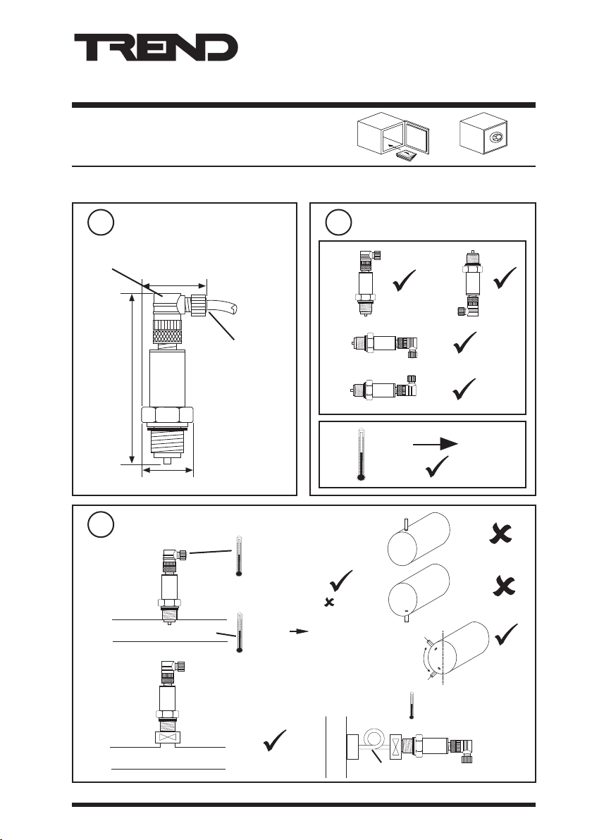
Dimensions
1
access for
connector screws
40 mm (1.57”)
110 mm (4.3”)
27 mm (1.06”)
Fixing requirements
3
a
b
isolating valve
cable
access
85 °C maximum
(185 °F)
P < 2.5 x range
[P > 2.5 x range
-25 °C
(-13 °F)
2
a
b
]
+125 °C
(+257 °F)
Requirements
-15 °C
(+5 °F)
c
70%
30%
d
if > +85 °C
(185 °F)
+85 °C
(185 °F)
100%
0%
ACC/SP
PIL3 Pressure Sensor (Liquid) Installation Instructions TG200127 Issue 4, 18/02/2009 1
Page 2

2 PIL3 Pressure Sensor (Liquid) Installation Instructions TG200127 Issue 4, 18/02/2009
PIL3 Installation Instructions
INSTALLATION (continued)
Fix sensor
4
G½“(DIN 259)
½“(BSP)
inside thread
Remove terminal cover
6
27 mm
Remove connector
5
a
knurled
ring
Remove cable compression nut
7
b
Feed cable through cover
8
a
b
c
d
Page 3

3
4
1
3
4
1
PIL3 Pressure Sensor (Liquid) Installation Instructions TG200127 Issue 4, 18/02/2009 3
Installation Instructions PIL3
INSTALLATION (continued)
Connect cable to screw terminals
9
IN (+) supply
IQ1xx, IQ2xx
24 V
IN
inside connector
OUT (-) signal
IN (+) supply
analogue input channel
linked for current (I)
OUT (-) signal
Replace terminal cover
10
Replace connector
12
a
IQ3
0 (0 V)
N (in)
+ (+24 V)
13
b
N
Tighten cable
11
compression nut
Congure IQ
I
IQ Conguration
Manual 90-1533
or
knurled
ring
Page 4

PIL3 Installation Instructions
INSTALLATION (continued)
14
Set up IQ sensor type
It is recommended to use SET (software Tool) for the setting of the sensor type module. For
all IQ2 series controllers with rmware version 2.1 or greater, or IQ3 series controllers, the
appropriate SET Unique Sensor Reference from those given below should be used:
PIL3/4: Pressure I 4 bar
PIL3/6: Pressure I 6 bar
PIL3/10: Pressure I 10 bar
PIL3/16: Pressure I 16 bar
PIL3/25: Pressure I 25 bar
Alternatively enter scaling manually as dened in table below:
For all other IQ controllers see the Sensor Scaling Reference Card TB100521A.
tYpe Sensor digI/P Driver Function loGic Loop
scHedule seQnc
Analog digBit Knob sWitch TimeZone Oss
User addRess intcoN calarM reView Plot calEndar
=?
Pressure Sensor
Yx<CR>
TYPE n
:
=?
S = 5 (characterise)
PIL3/4 2 (current) 2 4.1 0 2 4 20 0 4
PIL3/6 2 (current) 2 6.1 0 2 4 20 0 6
PIL3/10 2 (current) 2 10.1 0 2 4 20 0 10
PIL3/16 2 (current) 2 16.1 0 2 4 20 0 16
PIL3/25 2 (current) 3 25.1 0 2 4 20 0 25
Y E U L P I1 I2 O1 O2
Y=, E=, U=, L=, P=, I1=, I2=, O1=, O2=,
X <CR>
15
IQ
P = X
DISPOSAL
WEEE Directive :
At the end of their useful life the packaging and product, should
be disposed of by a suitable recycling centre.
Do not dispose of with normal household waste. Do not burn.
Please send any comments about this or any other Trend technical publication to techpubs@trendcontrols.com
© 2009 Honeywell Technologies Sàrl, ECC Division. All rights reserved. Manufactured for and on behalf of the Environmental and Combustion Controls
Division of Honeywell Technologies Sàrl, Ecublens, Z.A. La Pièce, 16, 1180 Rolle, Switzerland by its Authorized Representative.
Trend Control Systems Limited reserves the right to revise this publication from time to time and make changes to the content hereof without obligation
to notify any person of such revisions or changes.
Trend Control Systems Limited
P.O. Box 34, Horsham, West Sussex, RH12 2YF, UK. Tel:+44 (0)1403 211888 Fax:+44 (0)1403 241608 www.trend-controls.com
Trend Control System USA
6670 185th Avenue NE, Redmond, Washington 98052, USA. Tel:(425) 869-3900 Fax:(425) 869-8445 www.trend-controls.com
4 PIL3 Pressure Sensor (Liquid) Installation Instructions TG200127 Issue 4, 18/02/2009
 Loading...