

Page 1
Important: Retain these instructions
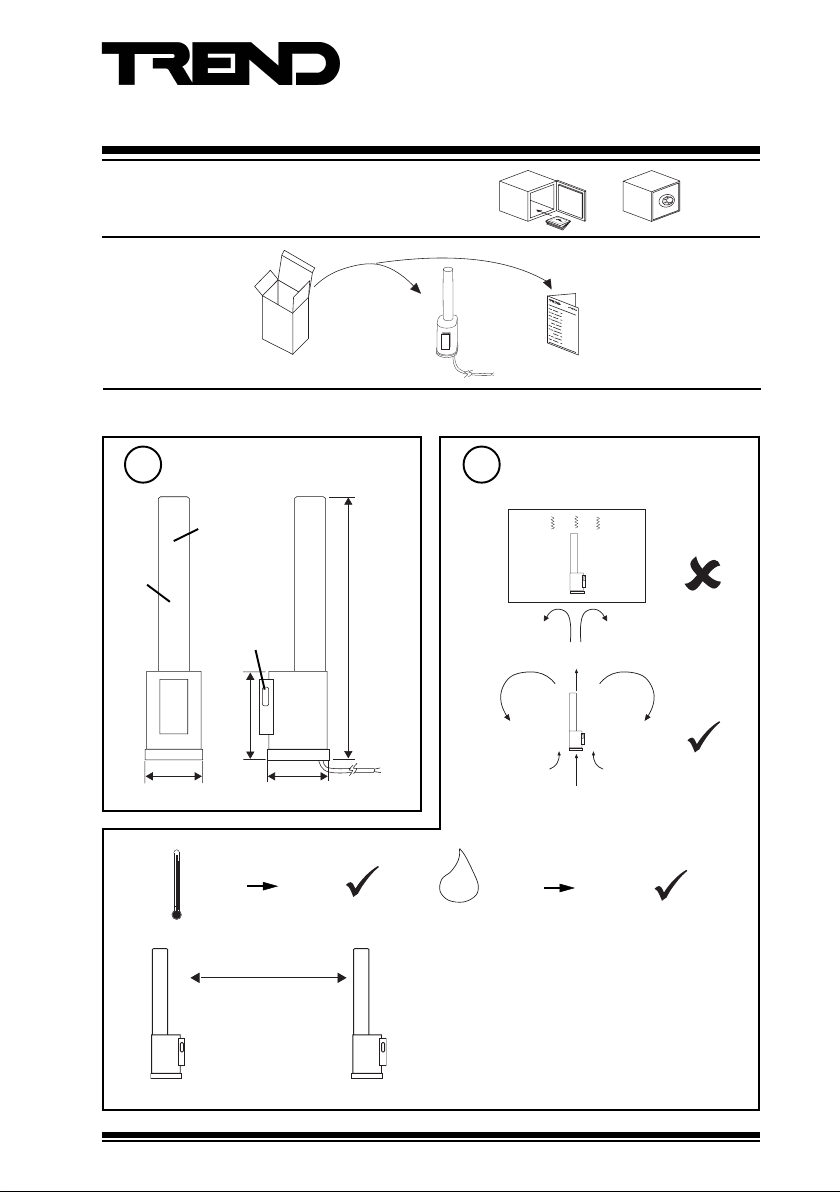
UNPACKING
INSTALLATION
Installation Instructions
PCW/...
Wireless Pulse Counters
PCW/... Installation
Instructions TG200834
Dimensions
1
Ø 20 mm
blue
body
mounting slot
37 mm 40 mm
b
-35 °C
c
PCW/...
75 m (maximum)
Note that range may be
affected by environmental
characteristics, e.g.
partitions, walls, building
structure etc.
45 mm
+60 °C
174 mm
2 m
XW/R/IQ
Requirements
2
a
H O
0 %RH
2
100 %RH
Protection IP68+
d
• Avoid using many other devices on frequency
range 433.05 to 434.79 MHz
• Keep away from sources of interference (e.g.
computer >1 m, microwave ovens, switch
mode power supplies).
• Mount above partition height if possible.
PCW/... Wireless Pulse Counters Installation Instructions TG200834 Issue 1/B 21/09/05
1
Page 2
PCW/... Installation Instructions
INSTALLATION (continued)
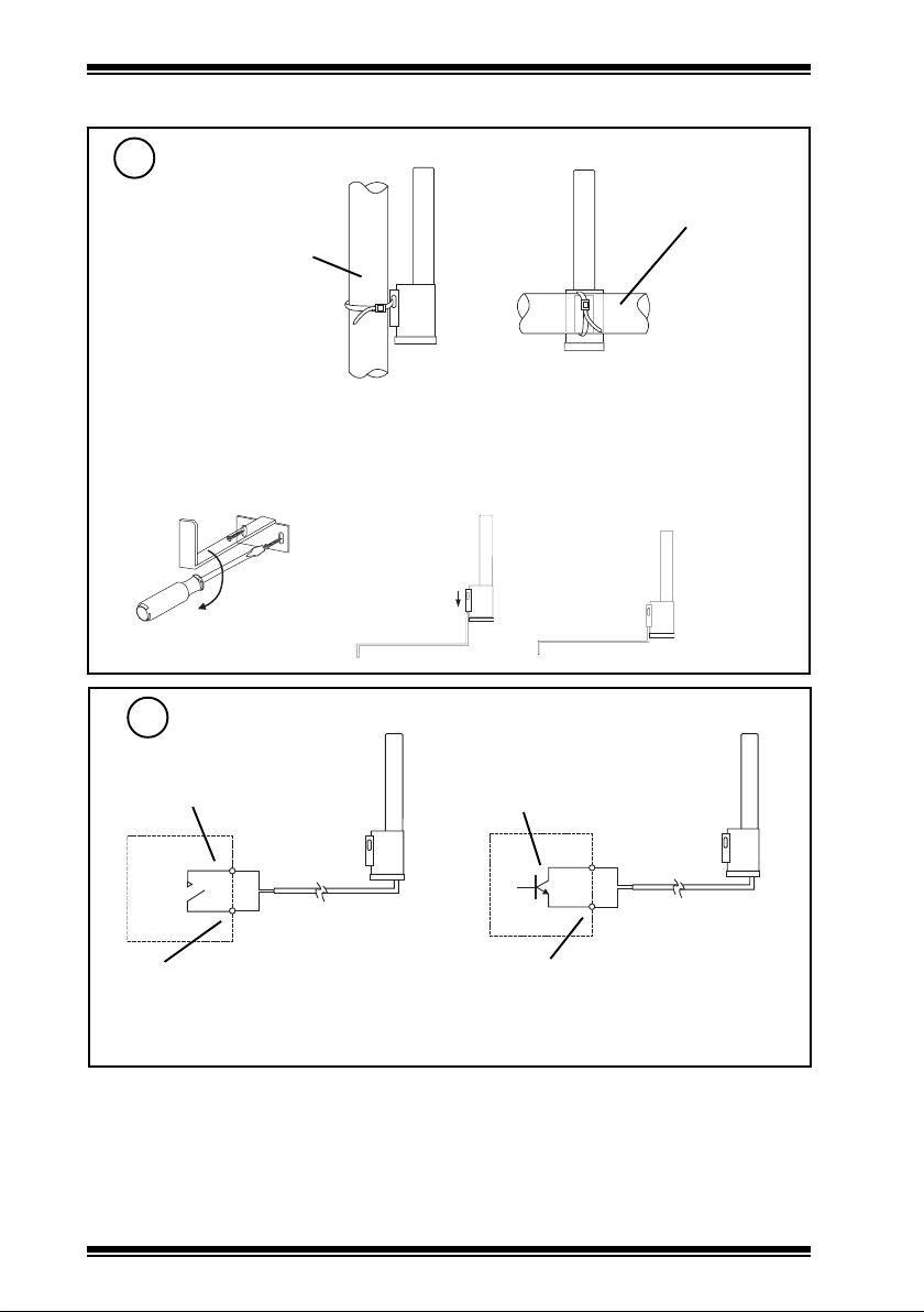
Mount Unit
3
(1) Using cable tie to pipe
horizontal
vertical pipe
Note that when monitoring hot water systems it is not advisable to mount the transmitter directly
on the pipe without intervening insulation.
(2) Using stainless steel bracket accessory ACCW/FK/SS
pipe
(a) (b)
use screws and rawl plugs
Connect Input
4
Volt free contact
Red (+)
Black (-)
polarity independent
Note that maximum pulse rate is 10/s.
Note that for PCW/STATUS, input state duration must be longer than 5s.
(c)
Transistor or optocoupler
Red (+)
Black (-)
Ensure correct polarity
PCW/... Wireless Pulse Counters Installation Instructions TG200834 Issue 1/B 21/09/052
Page 3
Installation Instructions PCW/...
X W / R /I Q
2 40 7 40 1
INSTALLATION (continued)
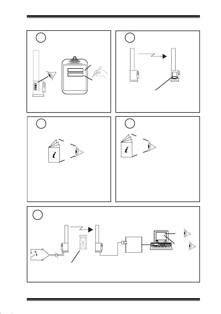
Note Identification Number
5
‘number’
000016746
00016746
Install and Configure
7
XW/R/IQ Receiver
XW/R/IQ Installation Instructions TG200783
Note that the PCW/... initial value should be recorded
as it will vary from unit to unit. The pulse counter
has been designed not to have reset capability in
order to prevent fraud.
‘location’
Check Receiver Serial
6
Number
PCW/...
For PCW/METER, XW/R/IQ serial number
is 2407401 or greater.
For PCW/STATUS, XW/R/IQ serial number
is 250517 or greater.
Configure IQ
8
For IQ3 the sensor’s target analogue node must
be created using SET. An example strategy
including decoding of alarm bits is given in the
TW/.., PCW/.., XW/R/IQ Data Sheet.
Alarm Bits:
Bit 3: loss of reception (from XW/R/IQ)
Bit 1: low battery (from sensor)
Bit 0: input state (from PCW/STATUS only)
XW/R/IQ
TW/.., PCW/..,
XW/R/IQ Data Sheet
TA200780
Test System
9
PCW/... Wireless Pulse Counters Installation Instructions TG200834 Issue 1/B 21/09/05 3
PCW/...
PCW/METER: 1 min.
PCW/STATUS: 4 min (and change of state)
XW/R/IQ
Δ V
IQ
Δ Status
Bit 3: loss of reception
Bit 1: low battery
Bit 0: input state
PCW/STATUS only
Page 4

PCW/... Installation Instructions
MAINTENANCE
The battery has a minimum life of 5 years. If the battery runs down the PCW/... receiver will set an alarm
bit in the status data sent with the value. This corresponds to bit 1 (Low alarm). When the battery has run
down, the unit should be returned to the IQ system supplier for battery replacement.
DISPOSAL
COSHH ASSESSMENT FOR DISPOSAL OF SENSOR. The only part affected is the lithium battery which
must be disposed of in a controlled way.
RECYCLING.
All plastic and metal parts are recyclable. The printed circuit board may be sent to any PCB recovery
contractor to recover some of the components for any metals such as gold and silver.
WEEE Directive :
At the end of their useful life the packaging,
product, and batteries should be disposed
Do not dispose of with normal household waste.
Do not burn.
of via a suitable recycling centre.
Manufactured for and on behalf of the Environmental and Combustion Controls Division of Honeywell Technologies Sàrl, Ecublens, Route
du Bois 37,Switzerland by its Authorized Representative, Trend Control Systems Limited.
Trend Control Systems Limited reserves the right to revise this publication from time to time and make changes to the content hereof
without obligation to notify any person of such revisions or changes.
Trend Control Systems Limited
P.O. Box 34, Horsham, West Sussex, RH12 2YF, UK. Tel:+44 (0)1403 21888 Fax:+44 (0)1403 241608 www.trend-controls.com
4
PCW/... Wireless Pulse Counters Installation Instructions TG200834 Issue 1/B 21/09/05
 Loading...