

Page 1
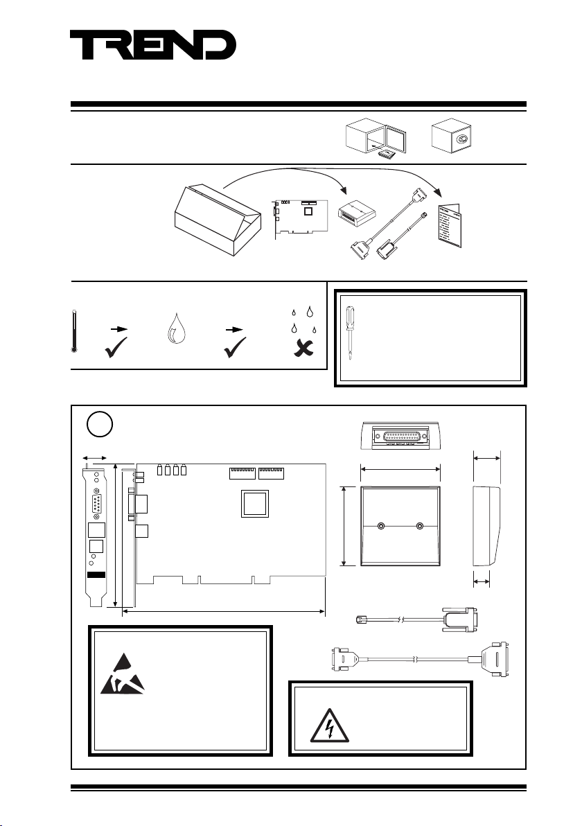
Installation Instructions
PACK/LNC2/STD
Lancard Node Controller
Important: Retain these instructions
1 Unpacking
Installation
Instructions
TG200240
Note that order code for full product is PACK/LNC2/STD. Code LNC2 is replacement board only.
2 Storage
-10 °C
(14 °F)
+70 °C
(158 °F)
HO
2
0 %RH
3 Installation
Dimensions
1
22 mm (0.87”)
L A N T X
L A N O K
L A N
R S 2 3 2
L O N
L O N
O K
S E R V I C E
127 mm (5”)
L N C 2
Caution: The LNC2 contains static
BS EN100015/1 Basic Specification:
protection of electrostatic sensitive
devices.
L A N R X
P C B U S Y
L A N B U S Y
L A N O K
L A N
180 mm (7.09”)
sensitive devices. Suitable
anti-static precautions
should be taken throughout
this operation to prevent
damage to the unit.
95 %RH
S W 1 S W 2
It is recommended that the installation
should comply with the HSE
Memorandum of Guidance on
Electricity at Work Regulations 1989.
For USA install equipment in accordance
with the National Electric Code.
27 mm
(1.06”)
80 mm (3.15”)
80 mm (3.15”)
16 mm (0.63”)
350 mm (13.78”)
2 m (6’ 6.74”)
WARNING: Opening the panel may
expose dangerous
voltages.
417-IEC-5036
PACK/LNC2/STD Installation Instructions TG200240 Issue 3 09/07/08
1
Page 2
PACK/LNC2/STD Installation Instructions
5 6 7 8
1 2 3 4 5 6 7 8
O N
P C
L A N
1 k 21 9 k 2 1 k 21 9 k 2
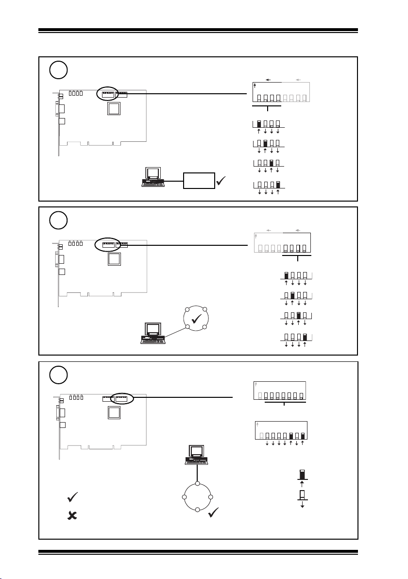
3 Installation (continued)
Set RS232 (PC to LNC2) baud rate
2
L AN T X
L A N R X
P C B U S Y
L A N B U S Y
L A N O K
L A N
S W 1 S W 2
top view
RS232 Baud Rate = R1
Set LNC2 to Lan baud rate
3
L A N T X
L A N R X
P C B U S Y
L A N B U S Y
L A N O K
L A N
S W 1 S W 2
top view
Lan Baud Rate = R2
= R1
= R2
LNC2
= R1
= R2
= R2
LNC2
= R2
DATA RATE
P C
O N
DATA RATE
SW1
19k2
9k6
4k8
1k2
L A N
1 k 21 9 k 2
1 k 21 9 k 2
1 2 3 4 5 6 7 8
SW1
19k2
5 6 7 8
9k6
5 6 7 8
4k8
5 6 7 8
1k2
1 2 3 4
1 2 3 4
1 2 3 4
1 2 3 4
Set Lan address
4
L A N T X
L A N R X
P C B U S Y
L A N B U S Y
L A N O K
L A N
S W 1 S W 2
top view
LAN ADDRESS
N O R M
SW2
D U M B
e.g
N O R M
D U M B
O N
O N
1 2 3 4 5 6 7 8
123 2 46 4 1 6
8
1 2 3 4 5 6 7 8
123 2 46 4 1 6
8
4 + 1 = 5
LNC2
Address = A
1, 4 to 9, 11 to 119
0, 2 to 3, 10, or >119
2
= A
≠ A
≠ A
≠ A
PACK/LNC2/STD Installation Instructions TG200240 Issue 3 09/07/08
Set
Not Set
Page 3
Installation Instructions PACK/LNC2/STD
LA N TX
LA N R X
LA N B U SY
PC B U S Y
LA N O K
LA N
S W 1 S W 2
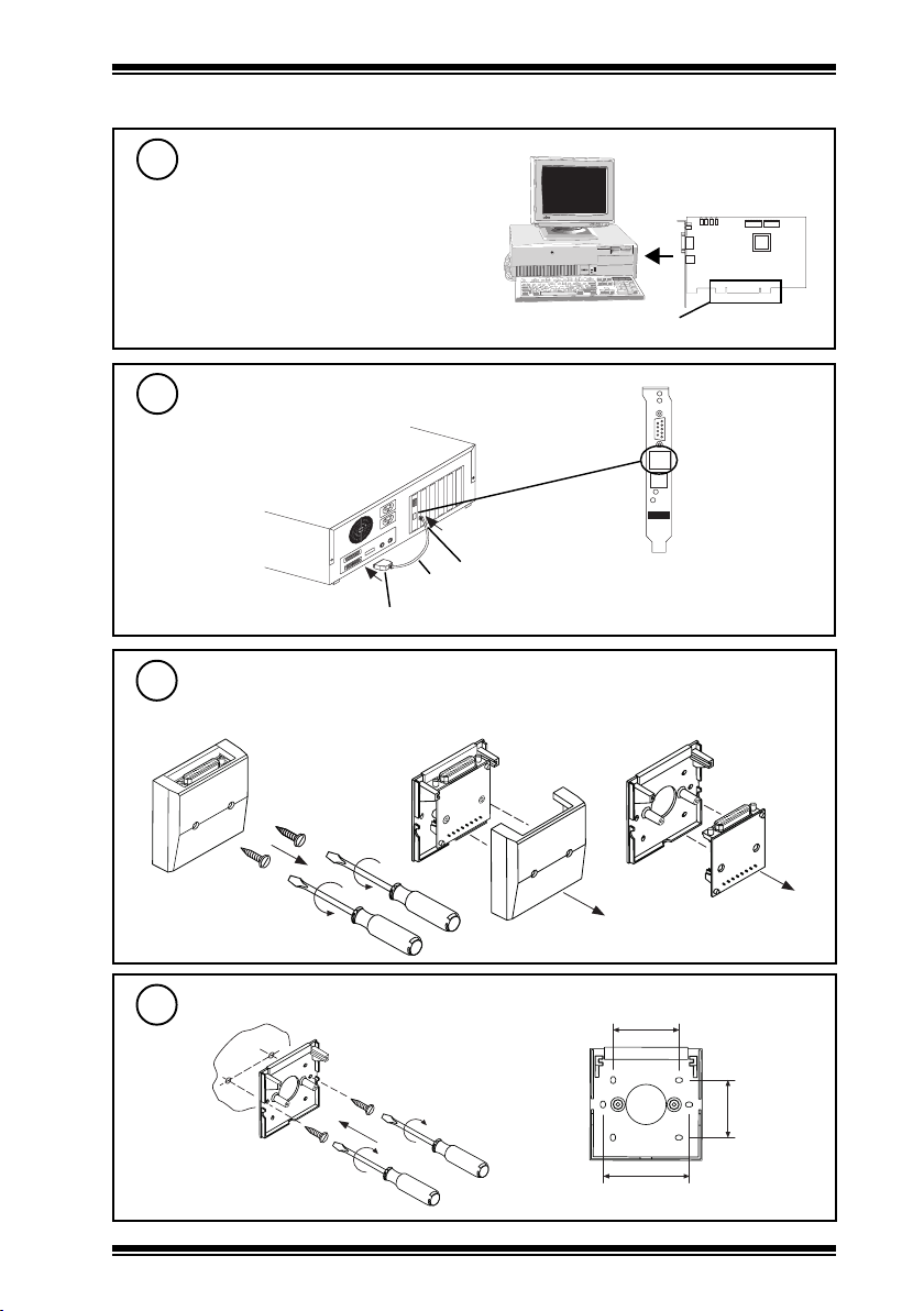
3 Installation (continued)
Fit the LNC2 into the PC
5
PACK/LNC2/STD/USA. The unit is UL rated as
‘UL916, accessory to open energy management
equipment’.
Follow PC manufacturer’s instructions for fitting
an expansion card
LNC2
PCI bus
Connect RS232, PC (COM port) to LNC2
6
LNC2 (RS232) RJ11 Male (cable)
Cable supplied
L A N O K
L A N
R S 2 3 2
L O N
L O N
O K
S E R V I C E
L N C 2
PC (COM port) 9 Way D type female (cable)
Dis-assemble Wallbox
7
abc
Mount Wallbox Base
8
45 mm (1.77”)
40 mm
(1.57”)
60 mm (2.36”)
PACK/LNC2/STD Installation Instructions TG200240 Issue 3 09/07/08
3
Page 4

PACK/LNC2/STD Installation Instructions
3 Installation (continued)
Connect Wallbox Board to Lan
10
4 wires
polarity independent
Wallbox
Network Engineering Manual
92-1735
T R T R
T R
T +
T -
T -
T R T R T R T R
To next
T +
device
2 wires
T R
Wallbox
T R
T R T R
To next
device
Terminal sizes 0.5 to 2.5 mm (14 to 20 AWG)
Terminate screens to earth (ground) at adjacent devices
Cable 1k2 baud 4k8 baud 9k6 baud 19k2 baud No. of
Belden 9182 1000 m
Belden 9207 1000 m
Trend TP/1/1/22/HF/200
(Belden 8761)
Trend TP/2/2/22/HF/200
Belden (8723)
(1090 yds)
(1090 yds)
1000 m
(1090 yds)
1000 m
(1090 yds)
1000 m
(1090 yds)
1000 m
(1090 yds)
1000 m
(1090 yds)
1000 m
(1090 yds)
1000 m
(1090 yds)
1000 m
(1090 yds)
700 m
(765 yds)
500 m
(545 yds)
T
T
R
R
R
R
J2 J3 J4 J5
J2 J3 J4 J5
700 m
(765 yds)
500 m
(545 yds)
350 m
(380 yds)
250 m
(270 yds)
T+T-R+
T+T-R+
Wires
2
2
2
4
R-
R-
To previous
device
T
T
R
R
To previous
device
T
T
Mount Wallbox Board
9
4
PACK/LNC2/STD Installation Instructions TG200240 Issue 3 09/07/08
Page 5

Installation Instructions PACK/LNC2/STD
3 Installation (continued)
Remove Cutout
11 12
(as appropriate)
Assemble Wallbox
13
Connect LNC2 Cable
14
to Wallbox
15
Route Cable
Connect LNC2 to Wallbox
LNC2 LAN 9 Way D type
Female (cable)
L A N O K
L A N
16
PACK/LNC2/STD Installation Instructions TG200240 Issue 3 09/07/08
Cable supplied
Switch on PC
O
I
R S 2 3 2
L O N
L O N
O K
S E R V I C E
L N C 2
5
Page 6

PACK/LNC2/STD Installation Instructions
S
R-
J2 J3 J4 J5
T+T-R+
S
3 Installation (continued)
17
18
Check LNC2
L A N T X
L A N O K
L A N
Check Network
L A N T X
L A N R X
P C B U S Y
L A N B U S Y
L A N O K
L A N
LAN OK
L A N R X
P C B U S Y
L A N B U S Y
LNC2 Faulty
T+T-R+
J2 J3 J4 J5
R-
W DOG (red)
LAN RX
a
(yellow)
LAN TX
b
(yellow)
LAN OK
c
(green)
LNC2 Faulty
?
Invalid Network Address
0, 2, 3 or >119
LNC2
LAN OK
O
I
L N C 2
L N C 2
?
Check network cabling for
short circuits with a
multimeter (NOT Megger)
Check baud rate. Switch
on other nodes until faulty
node is found (LAN OK
). Correct fault.
19
Check System
T=X °C (°F)
temperature ?
LNC2
T=X °C (°F)
Note that if the PC software using the LNC2 (e.g 963) is shut down, the LNC2 will generate a ‘Device
Dead’ alarm.
6
PACK/LNC2/STD Installation Instructions TG200240 Issue 3 09/07/08
IQ
Page 7

Installation Instructions PACK/LNC2/STD
4 Disposal
WEEE Directive :
At the end of their useful life the packaging
and product should anddisposed of by a
Do not dispose of with normal household waste.
Do not burn.
suitable recycling centre.
PACK/LNC2/STD Installation Instructions TG200240 Issue 3 09/07/08
7
Page 8

PACK/LNC2/STD Installation Instructions
This page is intentionally left blank
Please send any comments about this or any other Trend technical publication to techpubs@trendcontrols.com
© 2008 Honeywell Technologies Sàrl, ECC Divison. All rights reserved. Manufactured for and on behalf of the Environmental and Combustion Controls
Division of Honeywell Technologies Sàrl, Ecublens, Route du Bois 37, Switzerland by its Authorized Representative, Trend Control Systems Ltd.
Trend Control Systems Limited reserves the right to revise this publication from time to time and make changes to the content hereof
without obligation to notify any person of such revisions or changes.
Trend Control Systems Limited
P.O. Box 34, Horsham, West Sussex, RH12 2YF, UK. Tel:+44 (0)1403 21888 Fax:+44 (0)1403 241608 www.trend-controls.com
Trend Control Systems USA
6670 185th Avenue NE, Redmond, Washington 98052, USA. Tel: (425)897-3900, Fax: (425)869-8445 www.trend-controls.com
8
PACK/LNC2/STD Installation Instructions TG200240 Issue 3 09/07/08
 Loading...