

Page 1
Installation Instructions
OCC/U
Ultrasonic Occupancy Detection System
UNPACKING THE OCC/U
All versions are supplied individually boxed with installation instructions.
INSTALLATION
Mechanical
As the mechanical installation is different for each detector type, be sure to read each section carefully, and
select the appropriate procedure for your installation.
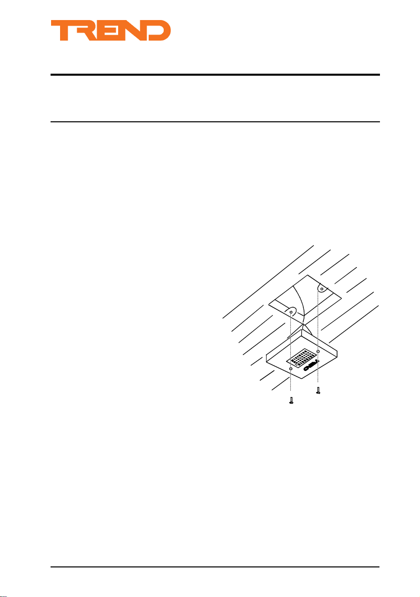
OCC/UD/DC
The detectors should be mounted in the ceiling at a
height of 2.4 to 3 m, in approximately the centre of
the area that is to be monitored.
(1) Ensure that a standard 25 mm single gang
sinking box is fitted into the ceiling at the
correct location.
(2) Insert a length of 3 core cable into the
sinking box and connect the three wires to
the screw terminals on the back of the
detector as shown in electrical section.
(3) Insert the detector into the sinking box, and
tighten the two screws.
OCC/U Ultrasonic Occupancy Detection System Installation Instructions TG101684 Issue 1/C 9/10/96
1
Page 2
OCC/U ULTRASONIC OCCUPANCY DETECTION SYSTEM Installation Instructions
AAAA
AAAA
AAAA
AAAA
AAAA
AAAA
AAAA
AAAA
AAAA
AAAA
AAAA
AAAA
AAAA
AAAA
AAAA
AAAA
AAAA
AAAA
AAAA
AAAA
AAAA
AAAA
AAAA
AAAA
AAAA
AAAA
AAAA
AAAA
AAAA
AAAA
AAAA
AAAA
AAAA
AAAA
AAAA
AAAA
AAAA
AAAA
AAAA
AAAA
AAAA
AAAA
AAAA
AAAA
AAAA
AAAA
AAAA
AAAA
AAAA
AAAA
AAAA
AAAA
AAAA
AAAA
AAAA
AAAA
AAAA
AAAA
AAAA
AAAA
AAAA
AAAA
AAAA
AAAA
AAAA
AAAA
AAAA
AAAA
AAAA
AAAA
AAAA
AAAA
AAAA
AAAA
INSTALLATION (continued)
OCC/UDA/DC
The detector should be mounted in the ceiling at a
height of 2.4 to 3 m. If surface mounting, the
detector’s ‘viewing’ angle should be carefully
considered before fixing. When ‘flush mounted’ the
viewing angle can be optimised after fixing. The
housing can be surface mounted using the back-box
provided, or ‘flush-mounted’ in a ceiling tile using
the rings provided.
If flush mounted:
(1) Make a 70 mm diameter hole where the
detector is to be mounted.
(2) Push out the cable entry at the top of the
detector.
(3) Pass a 3-core cable through ring B and the
hole in the ceiling tile. Ring B should be
above the ceiling.
(4) Undo the screws holding the two halves of
the detector together and separate them.
(5) Pass the cable through the cable entry in
the back-box and connect as shown in the
electrical section.
Flush Mounting diagram
Ring B
Push
back-box
Ring A
(6) Re-assemble the detector with Ring A
sandwiched between the two halves.
(7) Pass the tabs of Ring A through the ceiling
hole and snap Ring B into place.
(8) To remove detector simply rotate and pull
down.
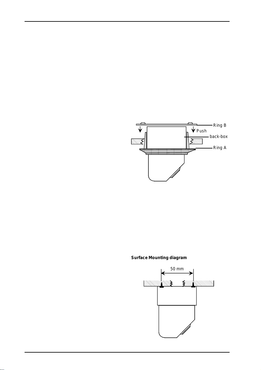
If surface mounted:
(1) Make a hole in ceiling and push a 3-core
Surface Mounting diagram
50 mm
cable through.
(2) Undo screws holding the two halves of the
detector together and separate them.
(3) Fix back-box directly to surface using
2 screws as shown in diagram right.
(4) Pass the cable through the cable entry in
the back-box and connect as shown in the
electrical section.
(5) Re-assemble the detector.
2
OCC/U Ultrasonic Occupancy Detection System Installation Instructions TG101684 Issue 1/C 9/10/96
Page 3

Installation Instructions OCC/U ULTRASONIC OCCUPANCY DETECTION SYSTEM
INSTALLATION (continued)
Electrical
(1) Isolate the mains supply to IQ controller
and lighting at source before commencing
the electrical connections.
(2) Wire the detector to the required IQ
Controller as shown below. Up to 10
detectors may be wired in parallel to a
single input channel.
Voltage Input
To other
detectors
(max 10)
0 V
SIG
24 Vdc
Detector
Digital Input
To other
detectors
(max 10)
0 V
SIG
24 Vdc
Detector
Note that it is important to set the IQ Controller’s
input to digital (or voltage on an IQ70 series), see
the appropriate controller data sheet for details.
IQ
Controller
Voltage
Input
IQ
Controller
24 Vdc
0 V
SIG
Aux Supply
Aux
Supply
Digital Input
0 V
24 Vdc
Detector
0 V
24 Vdc
Detector
24 Vdc
0 V
SIG
SIG
SIG
(3) Wire the output of the IQ Controller to the
lighting relay/contactor.
OCC/U Ultrasonic Occupancy Detection System Installation Instructions TG101684 Issue 1/C 9/10/96
3
Page 4

OCC/U ULTRASONIC OCCUPANCY DETECTION SYSTEM Installation Instructions
COMMISSIONING
Commissioning the Detectors
The commissioning of the detectors requires the
detectors to be positioned so that they cover the
required detection area, and may require their range
to be adjusted.
Positioning the detectors
(1) To position the detectors, move the detector
head until the required area is covered (UD
options move in one direction, UDA options
move in two directions).
Adjusting the range
This is not normally necessary as the detector is
factory set to suit most requirements, however
sometimes it may be necessary to reduce/increase
the detection pattern of the detector. To do this:
(1) Turn the lower adjustment screw until the
range is as required (clockwise reduces
the range).
Setting Up the IQ Controller
If an IQ Controller is being used to process inputs
from the OCC/U system, or to output a signal to it,
its strategy must be configured to do this. If a digital
input is used the necessary strategy should follow
the rules for fast sequencing.
Information on how to configure an IQ controller can
be found in the IQ Controller Configuration Reference
Manual (90-1533).
It is also important that the input and output channels
are configured to be of the correct type; this is
described in the appropriate controller’s data sheet.
UD option UDA option
30°
Adjustment angles
Voltage Input Scaling Table
IQ111, 131,
151 (non plus), 151+
U 10 10
L 0 0
T 5 10
B -5 -10
80°
Range Control
OTHER IQ'S
Trend Control Systems Ltd reserves the right to revise this publication from time to time and make changes to the content
hereof without obligation to notify any person of such revisions or changes.
Trend Control Systems Ltd P.O. Box 34 Horsham Sussex RH12 2YF Tel:+44 (0)1403 211888 Fax:+44 (0)1403 241608 www.trend-controls.com
4
OCC/U Ultrasonic Occupancy Detection System Installation Instructions TG101684 Issue 1/C 9/10/96
 Loading...