

Page 1
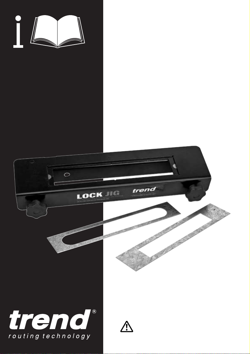
LOCK/JIG/A
For DDA (Disability Discrimination Act)
Style Lock Faceplate
20mm x 235mm (Rounded Ends)
24mm x 235mm (Rounded Ends)
Please read these instructions before use.
Page 2

LOCK/JIG/A
Dear Customer
Thank you for purchasing this Trend product,
we hope you enjoy many years of creative and
productive use.
Please remember to return your guarantee card
within 28 days of purchase.
CONTENTS
TECHNICAL DATA ____________________ 1
SAFETY PRECAUTIONS ______________2-3
ITEMS ENCLOSED ___________________ 4
DESCRIPTION OF PARTS ______________ 5
ACCESSORIES ______________________ 6
ASSEMBLY
- Setting the Spacer Fingers _____________ 7
- Choice of Set-ups - Option 1 ___________ 8
- Option 2 ____________________________ 9
- Option 3 ____________________________ 9
- Fitting the Guide Bush
- Steel Templates ____________________ 11
OPERATION
- Marking Out ________________________ 12
- Centring the Jig _____________________ 13
- Quick Centring for 44mm doors ________ 13
- Routing the Mortise
- Routing the Face-plate _______________ 14
- Finishing __________________________ 15
- Deeper Mortise _____________________ 15
- Cutting Key & Spindle Hole ___________ 15
MAINTENANCE _____________________ 15
ENVIRONMENTAL PROTECTION _______ 15
GUARANTEE _______________________ 15
SPARE PARTS
- Spare Parts List ____________________ 16
- Spare Parts Diagram _________________IB
_______________ 10
__________________ 14
TECHNICAL DATA
Cutter size 12mm
Min. workpiece 34mm
Max. workpiece 58mm
Template size 59.8mm x 299mm
Template size with adapter 59.8mm x 239mm
Guide bush size 30mm
Weight 3.4kg
The following symbols are used throughout this
manual:
Denotes risk of personal injury, loss of
life or damage to the tool in case of nonobservance of the instructions in this
manual.
Refer to the instruction manual of
your power tool.
This unit must not be put into service until it has
been established that the power tool to be
connected to this unit is in compliance with
2006/42/EC (identified by the CE marking on the
power tool).
INTENDED USE
The jig is intended to be used with a plunge
router fitted with suitable cutter and guide bush
to rout a mortise and faceplate recess for longer
locks in wooden doors. Standard templates
are for a lock with faceplate 20mm or 24mm
x 235mm with rounded ends. An auger bit is
required to drill the mortise deep enough for
DDA style locks.
☎
-1-
If you require further safety advice,
technical information or spare parts,
please call Trend Technical Support
or visit www.trend-uk.com
Page 3

LOCK/JIG/A
SAFETY
WARNING:
Observe the safety regulations in the
instruction manual of the power tool
to be used. Please read the following
instructions carefully. Failure to do so
could lead to serious injury. When using
electric tools, basic safety precautions,
including the following should always be
followed to reduce the risk of fire, electric
shock and personal injury. Also observe
any applicable additional safety rules.
Read the following safety instructions
before attempting to operate this product.
PLEASE KEEP THESE
INSTRUCTIONS IN A SAFE PLACE.
The attention of UK users is drawn
to The Provision and Use of Work
Equipment Regulations 1998, and any
subsequent amendments.
Users should also read the HSE/HSC
Safe Use of Woodworking Machinery
Approved Code of Practice and Guidance
Document and any amendments.
Users must be competent with
woodworking equipment before using our
products.
IMPORTANT NOTE:
Residual Risk. Although the safety
instructions and operating manuals for
our tools contain extensive instructions
on safe working with power tools, every
power tool involves a certain residual risk
which cannot be completely excluded
by safety mechanisms. Power tools
must therefore always be operated with
caution!
General
1. Disconnect power tool and
attachment from power supply
when not in use, before servicing,
when making adjustments and
when changing accessories such
as cutters. Ensure switch is in “off”
position. Always ensure cutter has
stopped rotating.
2. Always mount the power tool,
accessory or attachment in
conformity with the instructions. Only
use attachment and accessories
specified in the power tool manual.
The tool or attachment should not be
modified or used for any application
other than that for which it was
designed. Do not force tool.
3. Keep children and visitors away. Do
not let children or visitors touch the
tool, accessory or attachment. Keep
children and visitors away from work
area. Make the workshop child proof
with padlock and master switch.
4. Dress properly. Do not wear loose
clothing or jewellery, they can be
caught in moving parts. Rubber
gloves and non-skid footwear
is recommended when working
outdoors. Wear protective hair
covering to contain long hair.
5. Consider working environment. Do
not use the product in the rain or in
a damp environment. Keep work
area well lit. Do not use power tools
near gasoline or flammable liquids.
Keep workshop at a comfortable
temperature so your hands are
not cold. Connect machines that
are used in the open via a residual
current device (RCD) with an
actuation current of 30 mA maximum.
Use only extension cables that are
approved for outdoor use.
6. The accessory or attachment must
be kept level and stable at all times.
7. Keep work area clean. Cluttered
workshops and benches can cause
injuries. Ensure there is sufficient
room to work safely.
8. Secure idle tools. When not in use,
tools should be stored in a dry and
high or locked up place, out of reach
of children.
9. For best control and safety use
both hands on the power tool and
attachment. Keep both hands away
from cutting area. Always wait for the
spindle and cutter to stop rotating
before making any adjustments.
10. Always keep guards in place and in
good working order.
11. Remove any nails, staples and other
metal parts from the workpiece.
12. Maintain tools and cutters with care.
Keep cutters sharp and clean for
better and safer performance. Do
not use damaged cutters. Follow
instructions for lubricating and
changing accessories. Keep handles
dry, clean and free from oil and
grease.
13. Maintain accessories. Do not use
damaged accessories. Only use
accessories recommended by the
manufacturer.
14. Check damaged parts. Before
operation inspect the attachment,
the power tool, the cable, extension
cable and the plug carefully for signs
of damage. Check for alignment of
moving parts, binding, breakage,
mounting and any other conditions
that may effect its operation.
Have any damage repaired by an
Authorised Service Agent before
using the tool or accessory. Protect
tools from impact and shock.
15. Do not use tool if switch does not
turn it on or off. Have defective
switches replaced by an Authorised
Service Agent
16. Don’t over reach. Keep proper
footing and balance at all times. Do
not use awkward or uncomfortable
hand positions.
17. Don’t abuse the cable.Never carry
-2-
power tool or accessory by cord or
pull it to disconnect from the socket.
Keep cord from heat, oil and sharp
edges. Always trail the power cord
away from the work area.
18. Connect dust extraction equipment.
If devices are provided for the
connection of dust extraction and
collection facilities, ensure these are
connected and properly used.
19. Check all fixing and fastening nuts,
bolts and screws on power tool,
attachment and cutting tools before
use to ensure they are tight and
secure. Periodically check when
machining over long periods.
20. Stay alert. Watch what you are
doing. Use common sense. Do not
operate tools when you are tired,
under the influence of drugs or
alcohol.
21. Personal Protective Equipment
(PPE) for eye, ear and respiratory
protection must be worn. All PPE
must meet current UK and EU
legislation.
22. Do not leave tools running
unattended. Do not leave tool until it
comes to a complete stop.
23. Always clamp workpiece being
machined securely.
24. Only use cutting tools for
woodworking that meet EN8471/2 safety standards, and any
subsequent amendments.
25. Vibration levels. Hand held power
tools produce different vibration
levels. You should always refer
to the specifications and relevant
Health & Safety Guide.
Routing Safety
1. Read and understand instructions
supplied with power tool, attachment
and cutter.
2. Keep hands, hair and clothing clear
of the cutter.
3. Remove adjusting keys and
spanners. Check to see that keys
and adjusting spanners are removed
from the router tool, cutter and
attachment before turning router on.
Make sure cutter can rotate freely.
4. Noise. Take appropriate measures
for the protection of hearing if
the sound pressure of 85dB(A) is
exceeded. Routing sound pressure
may exceed 85dB(A), so ear
protection must be worn.
5. Eye protection. Always wear eye
protection in the form of safety
goggles, spectacles or visors to
protect the eyes.
6. Respiratory protection. Wear a
face or dust mask, or powered
respirator. Dust masks/filters should
be changed regularly.
Page 4

LOCK/JIG/A
7. Do not switch router on with the
cutter touching the workpiece. At the
end of the cut, release the router
plunge and allow spindle to stop
rotating. Never use the spindle lock
as a brake
8. The direction of routing must always
be opposite to the cutter’s direction
of rotation. Do not back-cut or climbcut.
9. Check before cutting that there
are no obstructions in the path of
the router. Ensure there are no
obstacles beneath workpiece when
cutting full thickness, and that a
sacrificial work surface is used.
Router Cutter Safety
1. Cutting tools are sharp. Care should
be taken when handling them. Do not
drop cutters or knock them against
hard objects. Handle very small
diameter cutters with extra care.
Always return cutter to its packaging
after use.
2. Always use cutters with a shank
diameter corresponding to the size of
the collet installed in your tool.
3. The maximum speed (n.max) marked
on the tool, or in instructions or on
packaging shall not be exceeded.
Where stated the speed range shall
be adhered to. Recommended
speeds are shown in the Trend
Routing Catalogue and/or website.
Always use router cutters in a router.
4.
Drill and boring bits must not be
used in a router. Router cutters
must only be used for the material
cutting application for which they are
designed. Do not use on metal or
masonry.
5. Never use cutters with a diameter
exceeding the maximum diameter
indicated in the technical data of the
powertool or attachment used.
Before each use check that the
6.
cutting tool is sharp and free from
damage. Do not use the cutting tool
if it is dull, broken or cracked or if in
any other damage is noticeable or
suspected.
Cutters should be kept clean. Resin
7.
build up should be removed at
regular intervals with Resin Cleaner.
The use of a PTFE dry lubricant will
reduce resin build up. Do not use
PTFE spray on plastic parts.
8. When using stacked tooling (multi-
blade, block and groover etc.) on a
spindle arbor, ensure that the cutting
edges are staggered to each other to
reduce the cutting impact.
9. Cutter shanks should be inserted
into the collet all the way to the line
indicated on the shank. This ensures
that at least
is held in the collet. Ensure clamping
3
⁄
4
of the shank length
surfaces are cleaned to remove dirt,
grease, oil and water.
10. Observe the correct assembly and
fitting instructions in the router
instruction manual for fitting the
collet, nut and cutter.
11. Tool and tool bodies shall be
clamped in such a way that they will
not become loose during operation.
Care shall be taken when mounting
cutting tools to ensure that the
clamping is by the shank of the
cutting tool and that the cutting
edges are not in contact with each
other or with the clamping elements.
12. It is advisable to periodically check
the collet and collet nut. A damaged,
worn or distorted collet and nut can
cause vibration and shank damage.
Do not over-tighten the collet nut
13. Do not take deep cuts in one pass;
take several shallow or light passes
to reduce the side load applied to the
cutter and router. Too deep a cut in
one pass can stall the router.
14. In case of excessive vibrations whilst
using the router stop immediately
and have the eccentricity of the
router, router cutter and clamping
system checked by competent
personnel
15. All fastening screws and nuts should
be tightened using the appropriate
spanner or key and to the torque
value provided by the manufacturer.
Extension of the spanner or
16.
tightening using hammer blows shall
not be permitted.
17. Clamping screws shall be tightened
according to instructions provided by
the manufacture. Where instructions
are not provided, clamping screws
shall be tightened in sequence from
the centre outwards.
Using Routers In A Fixed Position
1. Attention should be made to the
HSE’s Safe Use of Vertical Spindle
Moulding Machines Information
Sheet No.18 and any revisions.
After work, release the router plunge
2.
to protect the cutter.
3. Always use a push-stick or push-
block when making any cut less than
300mm in length or when feeding the
last 300mm of the cut.
4. The opening around the cutter
should be reduced to a minimum
using suitably sized insert rings in
the table and closing the back fence
cheeks or fitting a false fence on the
back fence.
5. Whenever possible use a work
holding device or jig to secure
component being machined. Ensure
any attachment is securely fitted to
the workbench, with table surface at
-3-
approximately hip height.
6. Use a No-Volt Release Switch.
Ensure it is fixed securely, easily
accessible and used correctly.
7. In router table (inverted) mode, stand
to the front right of the table. The
cutter will rotate anti-clockwise when
viewed from top so the feed direction
is from the right (against the rotation
of the cutter). In overhead mode,
stand to the front left of the machine
table and the feed direction is from
the left.
8. Do not reach underneath table or
put your hands or fingers at any
time in the cutting path while tool is
connected to a power supply.
9. Never thickness timber between the
back of the cutter and the backfence.
Useful Advice When Routing
1. Judge your feed rate by the sound
of the motor. Feed the router at a
constant feed rate. Too slow a feed
rate will result in burning.
Trial cuts should be made on waste
2.
material before starting any project.
3. When using some attachments e.g.
a router table or dovetail jig, a fine
height adjuster is recommended.
4. When using a template guide bush,
ensure there is sufficient clearance
between cutter tip and inside edge
of bush and that it cannot come into
contact with collet and nut. Ensure
cutter and guide bush are concentric.
Router Cutter Repair/Maintenance
1. Repair of tools is only allowed in
accordance with the manufacturers
instructions.
2. The design of composite (tipped)
tools shall not be changed in process
of repair. Composite tools shall be
repaired by a competent person i.e.
a person of training and experience,
who has knowledge of the design
requirements and understands the
levels of safety to be achieved.
3. Repair shall therefore include, e.g.
the use of spare parts which are in
accordance with the specification
of the original parts provided by the
manufacturer.
4. Tolerances which ensure correct
clamping shall be maintained.
5. Care shall be taken that regrinding
of the cutting edge will not cause
weakening of the body and the
connection of the cutting edge to the
body.
Version 7.2 06/2013
Page 5
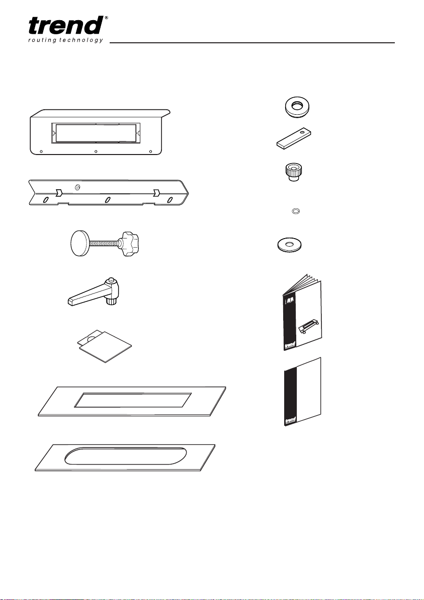
ITEMS ENCLOSED
LOCK JIG
GUARANTEE
LOCK/JIG/A
x1
Mortise x1
x3
x1
x2
x1
x6
x2
x1
x2
x3
LOCK JIG
x1
LOCK JIG
x1
GUARANTEE
Face-plate x2
ITEMS REQUIRED
■ 1/2” collet plunge router (or 1/4” collet
plunge router if used for faceplate only).
■ 30mm guide bush (or 16mm plus collar).
■ 12mm diameter router cutter with
suitable shank size.
■ Door clamping device.
■ Hand tools.
-4-
Page 6
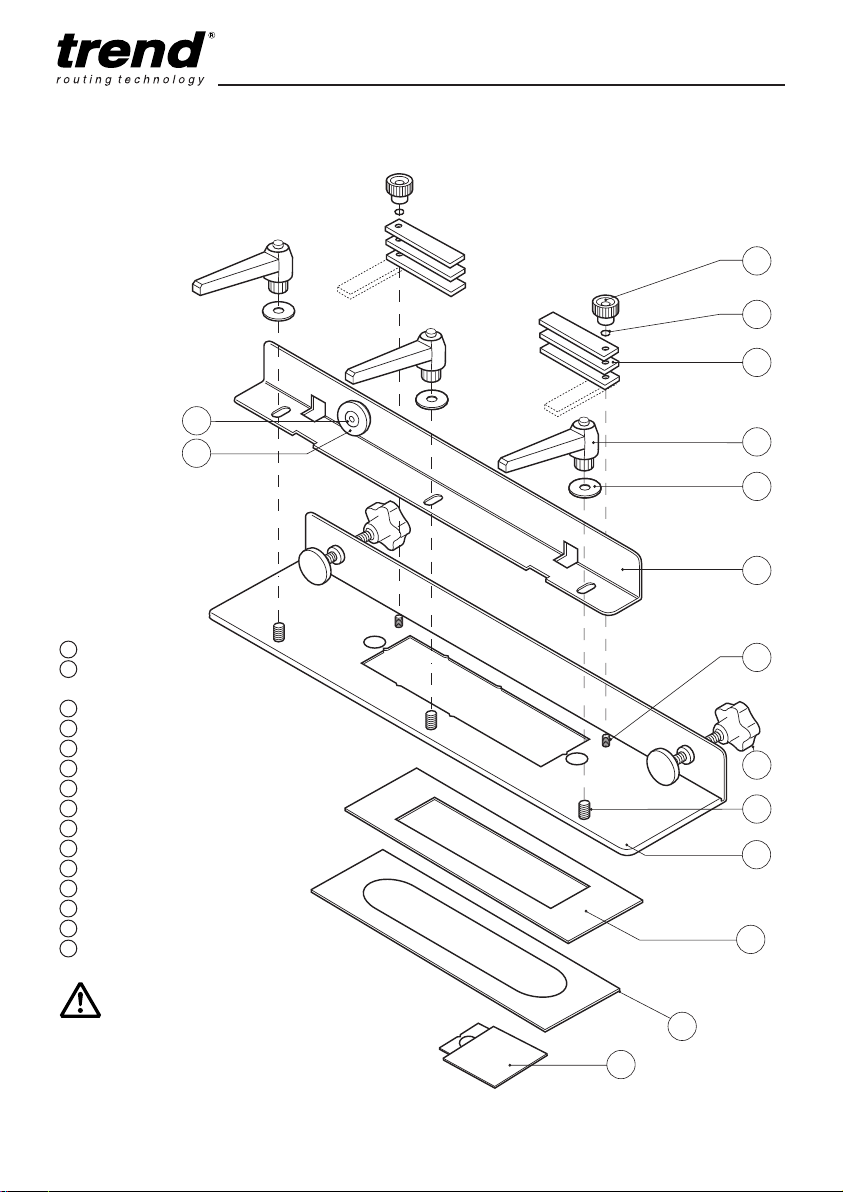
DESCRIPTION OF PARTS
Use the drawing below as a guide to
assemble the jig.
LOCK/JIG/A
I
H
G
E
D
C
A Jig body
B Adjustable lever
fixing stud
C Clamp bar
D Adjustable lever washer
E Adjustable lever M8
F Spacer finger fixing stud
G Spacer finger
H Spring washer
I Mini knob M5
J Guide bush collar 16mm to 30mm
K Collar park
L Mortise template
M Face plate template
N Clamping knob with pad
O Adapter plate for smaller templates.
Ensure jig is clean and
free from oil before use.
F
B
A
-5-
Page 7
LOCK/JIG/A
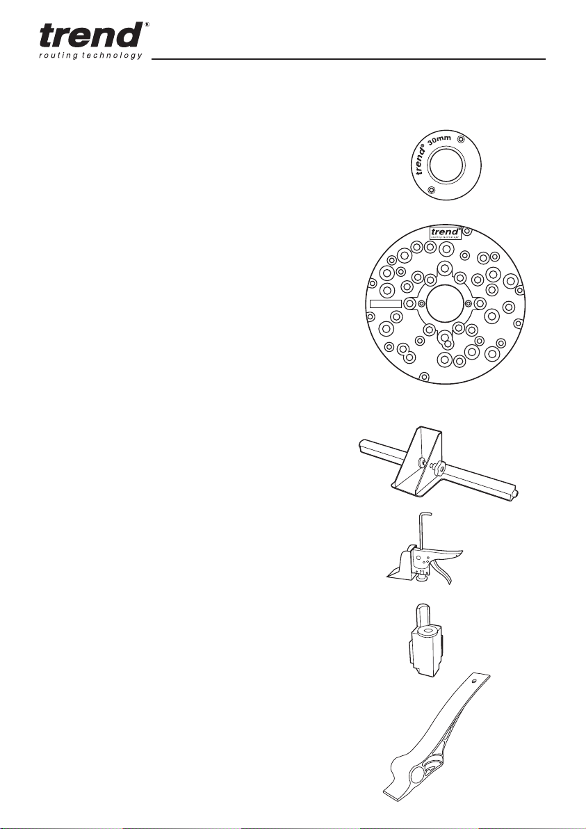
ACCESSORIES
Please use only Trend original accessories.
30mm Guide Bush
Ref. GB30
Should the correct guide bush not be available to suit your router’s
base, you will need to use the Trend UNIBASE in conjunction with a
30mm guide bush, Ref. GB30 or 16mm guide bush Ref. GB160.
Universal Sub-base
Ref. UNIBASE
The Unibase contain screws, a line up bush and pin.
The line up pin and bush ensure exact alignment of
sub-base with the router spindle, when fitted with the
relevant collet.
Fits following router models
Atlas Copco OFSE2000 Bosch GOF 1300ACE, 1600A,
1700ACE Casals FT2000VCE CMT CMT1850, 2000,
DeWalt DW624, 625EK, 629 Draper R1900V Elu MOF 131,
177(E) Felisatti TP246(E), R346EC Festo OF2000E Freud
FT2000E Hitachi M12V, M12SA, TR12 Metabo OF1612,
OFE1812 Ryobi RE600N, R600N, RE601, R500, R502 Skil
1875U1 Wadkin R500
Door Stand
Ref. D/STAND/A
Holds door on it’s edge whilst routing hinge recess
and mortise for locks. Maximum weight 50kg and for
doors 32mm to 55mm thick. Allows door to be tilted
back to assist fitting to door frame.
UNIBASE
Door Clamp
Ref. D/CLAMP/A
Holds door open in a fixed position whilst drilling and
fitting locks. Ratchet clamp design for doors up to
55mm thick.
Corner Chisel
Ref. C/CHISEL
For square edged lock faceplates. Squares up
rounded corners in one operation with the tap of a
hammer. High speed steel anvil.
Door Lifter
Ref. D/LIFT/A
Foot operated lifter to support door while fitting into
door frame.
-6-
Page 8
LOCK/JIG/A
ASSEMBLY
■ Remove the transit washer and nut from the
middle adjusting lever fixing stud on the jig
body. Fit the three washers, and fit the three
adjustable levers. To tighten the adjustable
levers, lift the lever up and rotate the knurled
part whilst keeping the lever body stationary.
When hand-tight, release the ratchet and
tighten using the lever.
■ Remove the protective film from the spacer
fingers then place three spacer fingers onto
the spacer finger fixing stud. See Setting
the Spacers (right) for adjustment. Fit the
spring washer and the mini knob onto the
spacer finger fixing stud and tighten. Repeat
procedure for other assembly.
In some circumstances when a guide
bush with a long spigot is used it may
contact the clamping bar, if this occurs
a shallower spigot guide bush will be
required.
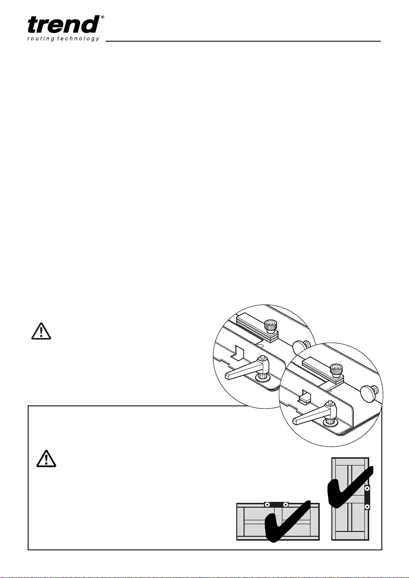
Setting the Spacer Fingers
■ Spacers may need to be used to ensure the
spigot of the guide bush will not contact the
door edge when routing.
■ Three spacers per end of the jig are provided
and can be parked against the jig body when
not required.
■ Clamp the jig to the door and place the router
fitted with guide bush into the aperture. If the
guide bush does not contact the door edge,
then no spacers need to be used.
■ If the guide bush contacts the door edge
calculate how many spacers are required.
Each spacer is 2mm thick.
■ To reposition the spacers, undo each of the
two M5 knobs, remove knob and washer and
lift off the spacers. Reposition the required
number of spacers by 90° so they line up
across the jig and replace all unused spacers.
Ensure an equal number of spacers are used
at each end. Refit the washers and the M5
knobs and tighten.
No spacer
fingers used.
One spacer
finger used.
Special Note:
The Ref. LOCK/JIG/A can be used to cut the faceplate recess in the edge of doors whilst it is hung.
The mortise should NOT be routed
when the door is hung.
Always ensure that the door is firmly
secured if routing the face-plate on a
hung door, so there is no possibility of
the door swinging open or shut.
-7--7-
Face-plate only
Face-plate and mortise
Page 9
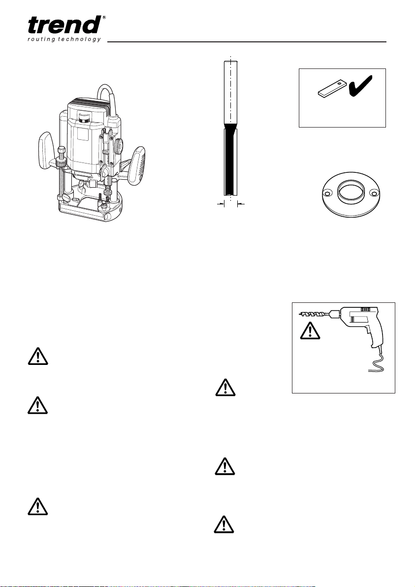
Choice of Set-ups
Option 1
4
LOCK/JIG/A
One Spacer required
with T9/T10/T11 routers.
+
Heavy duty router with
1
⁄2” collet e.g. T10 Router
Suitable Plunge Router:
Your router should have following
plunge length:
- For 2” deep locks at least 54mm.
1
- For 2
- Auger bit and drill required for 3”
It is recommended that a plunge
router is used.
Fit sufficient length of the shank
into the collet. Ideally at maximum
plunge, only as much of the cutter
should protrude below the base as
is required to reach the depth of the
mortise.
⁄
2
” deep locks at least 66mm.
deep locks for all routers.
with the following routers:
RYOBI R600, R600(N), RE601
+
12mm
Router Cutter
Ref. TR37X1/2TC
or C172X1/2TC
or 3/75X1/2TC
overall length 115mm
OR USE
Router Cutter
Ref. TR37MX1/2TC
or C172MX1/2TC
or 3/75MX1/2TC
overall length 100mm
Makita 3612(C)
Skil 1875U1
Due to the extra long length of this
cutter, extra care should be taken
to avoid damage. The cutter should
be used to plunge rout a series of
overlapping holes. See page 14.
For deep body locks over 75mm an
auger bit in a drill needs to be used to
complete the mortise.
30mm Guide Bush
Ref. GB30
See page 6 if a
suitable guide bush
is not available
for your router.
Deepening of
mortise with
auger bit and
drill will be
required.
Do not attempt to increase the
depth of cut by having less than the
optimum length of the cutter’s shank
inserted in the collet of your router.
The guide bush Ref. GB30/A cannot
be used with the jig for internal doors.
-8--8-
Page 10
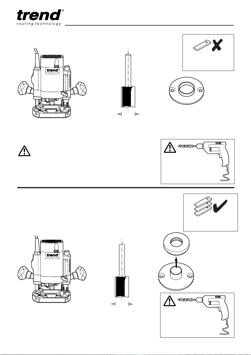
Option 2
LOCK/JIG/A
No Spacers required
with T5 router.
+
12mm
Medium duty router with
1
⁄4” collet e.g. T5 Router
The guide bush Ref. GB30/A cannot
be used with the jig for internal doors.
Option 3
Using the Lock Jig with the Trend Hinge Jig
■ If the Lock Jig is to be used in conjunction with the Trend Hinge
Jig, use the Guide Bush Collar to bush out the 16mm guide bush
(supplied with the Hinge Jig) to 30mm diameter. This makes it
unnecessary to change guide bushes between operations.
Router Cutter
Ref. 3/8LX1/4TC
or TR12X1/4TC
or C019AX1/4TC
+
+
+
30mm Guide Bush
Ref. GB30
Deepening of
mortise with auger
bit and drill will be
required.
Three Spacers required
with T5 router.
Guide Bush Collar
Ref. GB/COLL/1630
Supplied with Lock Jig
16mm Guide
Bush Ref.
GB160
Supplied with
Hinge Jig
Medium duty router with
1
⁄4” collet e.g. T5 Router
12mm
Router Cutter
Ref. 3/8LX1/4TC
or TR12X1/4TC
or C019AX1/4TC
-9--9-
Deepening of
mortise with auger
bit and drill will be
required.
Page 11
LOCK/JIG/A
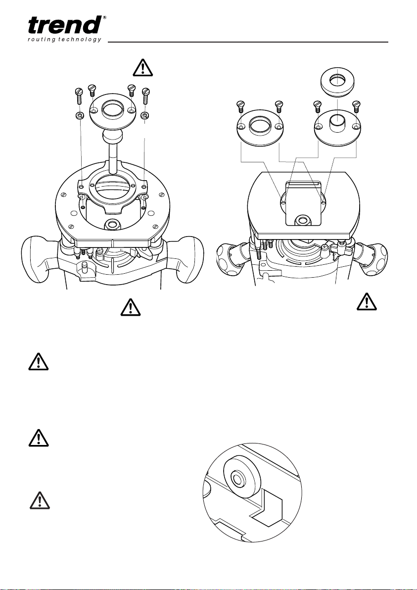
Fitting the Guide Bush
Ref. GB30
Fitting Guide Bush to
T10/T11 Router
■ If using the Trend T10/T11 Router, fit a 30mm
guide bush Ref GB30. Make sure the bush is
correctly centred.
If there is any doubt about the
concentricity of cutter relevant to
the guide bush, then a sub-base
should be used in order to ensure an
accurate fit of face-plate.
Guide bush
collar
Ref. GB30
Ref. GB160
Fitting Guide Bush to T5 Router
■ If using the Trend T5 Router, purchase and fit
a GB30.
■ If using the Hinge Jig, fit the GB160 supplied
with the Hinge Jig. By using the Guide Bush
Collar supplied with the Lock Jig, the same
router set-up can be used by simply fitting
the collar in between the hinge and lock
operations.
■ The guide bush collar can be stored on the
spigot fixed to the outside of the clamp bar
when not in use.
Ensure guide bush collar is fitted fully
onto the guide bush with chamfer
facing the jig.
Frequently check that the guide bush
collar is seated properly on the guide
bush. Check that the collar has not
worked loose otherwise this will
affect the cut.
Make sure guide bush
collar is fitted with
chamfered edge facing
the jig when parked.
This will make it easier
to remove.
-10--10-
Page 12

LOCK/JIG/A
Steel Templates
■ Mortise template A has a smaller aperture for
the lock body, the faceplate template has a
larger aperture.
A
1
■ They are attached to the jig by means of
the two strong magnets incorporated in the
jig body. Ensure that the seating for the
template is free of wood dust.
■ The templates are reversible and have no
defined top or bottom.
■ For the latest information on templates
available, see our website -
www.trend-uk.com/downloads
or call Trend Technical Support.
Smaller Template Adapter Plate
Face-plate Dimensions:
Size Template Style
20mm x 235mm 1 Rounded Ends
24mm x 235mm 2 Rounded Ends
■ The adapter plate allows the LOCK/JIG/A
to use the smaller templates (overall size
239mm x 60mm) that are supplied for the
standard LOCK/JIG. Sight marks on the jig
allow centering of jig.
Before using the face-plate template,
check the template is exactly 18mm
bigger than the actual lock face plate.
Mortise Dimensions:
Size Template Style
17mm x 170mm A Standard*
*Mortise is actually 180mm to give 5mm clearance at each end.
Templates have square corners, so
care must be taken when handling.
Ensure working position is comfortable
especially when setting up and when
routing on door edge. Keep proper
footing and balance at all times.
-11-
-11-
Page 13
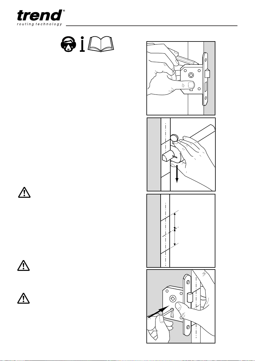
OPERATION
Marking Out
■ Choose the position of the lock carefully.
Position the lock with the centre of the spindle
aperture at approximately 1m above the floor.
Whilst the lock is on the edge of the door,
mark the top and bottom of the lock case on
the door edge. Do not choose a position
where the cross member joins the stile as it
will weaken the door.
■ Then using a marking gauge set to half the
thickness of the door, join the marks to show
where the centre line of the mortise lock will
be. Ensure the centre line is long enough to
sight them on the centre line notches on the
jig body.
■ Mark a horizontal line across the edge at the
centre of your lock position. You now have
two centre lines to line up with the notches on
the jig body.
LOCK/JIG/A
C
L
Please note, the centre of the mortise
may not be on the centre line of the
spindle hole.
■ Mark out the spindle and keyhole position on
the face of the door as normal using a paper
template or the lock body as shown with a
bradawl (ensuring the front of the lock is flush
with the door edge).
Ensure door is clamped and securely
held when using the jig.
Ensure working position is
comfortable, especially when setting
up and when routing a door edge.
-12--12-
C
L
Page 14
LOCK/JIG/A
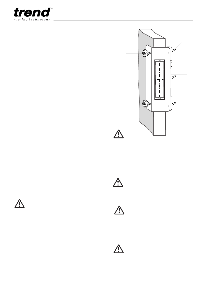
Centring the Jig
When using the lock jig, the clamp bar is used as the
datum edge. Before the jig can be used the clamp
bar datum has to be set by the user. The jig template
aperture recess has v notches that are punched into the
jig body. Due to the manufacturing tolerances there may
be some deviation between the v notches, subsequently
the notches should only be act as an initial guide to
position the jig on the door. Furthermore when the spacer
fingers are used this raises the jig higher making it more
difficult to align to the pencil marks to the v notches.
■ After the lock position has been marked on the
door, loosen the two lobe clamping knobs and
the three adjustable levers (which are a ratchet
type and require lifting to change their position)
so that the jig can fit to the door.
■ Initially set up jig using the v notches to get an
approximate centre of the door.
■ To set the jig accurately, either measure with
a rule or tape to position jig template aperture
recess centrally, or place the largest template
into the jig and look down vertically to gauge
position. Adjust the two clamping knobs
accordingly to move the jig forward or backwards
to centre. Once the jig is centred and parallel,
slide the clamping knob against the door edge
and tighten the adjustable levers.
■ Check clamping bar is fully against the door
edge and adjust adjustable levers if necessary.
The datum has now been set.
■ The jig can now be clamped into position by
tightening the two lobe knobs. Only gentle
pressure is required.
Adjustable
levers
Lobe
knobs
Jig template
aperture recess
Clamp bar
(datum)
The jig template aperture recess
notches in the jig central aperture
are to be used as an initial visual
guide only, always check the jig and
template is centred to the door using
a rule or tape measure before routing.
Make sure the correct templates
are used for the mortise and for the
face-plate.
Do not over-tighten lobe knobs as
damage to the door or jig may occur.
■ Once set, the only marking requirement for
further doors of same thickness is a single offset
measurement from the rail or bottom of the door
to the top of the jig.
Special Note:
If fitting the lock to a non-solid core door, ensure
the lock block is located first.
Trial cuts should be made on waste
material to check correct templates
have been selected, the jig is set up
accurately and that the face plate /
mortise is central.
The result of using this jig depends
on how accurately the lock markings
on the door are marked and how
accurately the jig is set.
-13--13-
Page 15
LOCK/JIG/A
See special
note on page 7.
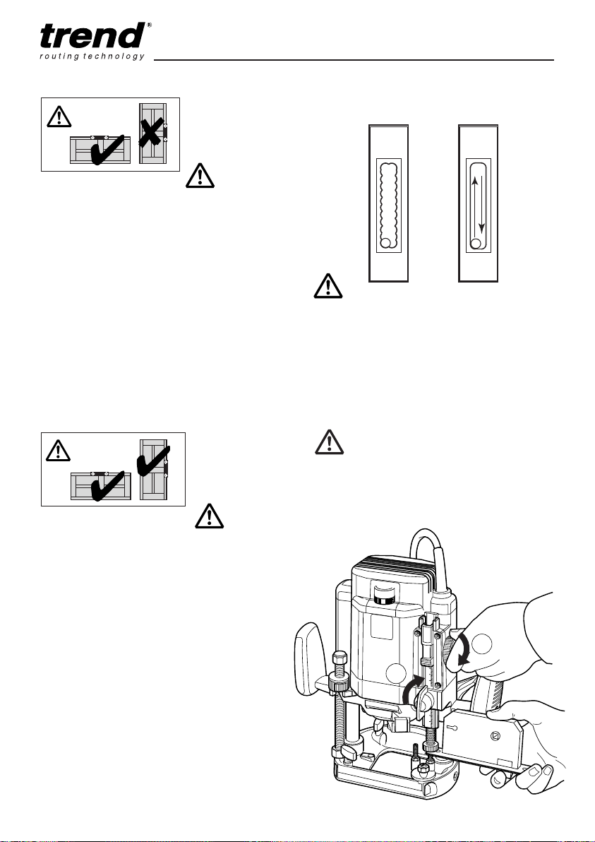
Routing the Mortise
■ Fit the relevant mortise template to the jig
body eg A . Ensure that seating for template is
free of wood dust.
■ Plunge rout the mortise by drilling a series of
overlapping holes no more than 20mm deep.
■ Make sure plunge locking lever of router
is locked and then clean up by making a
shallow pass no more than 20mm around the
template in a clock-wise direction.
■ Remove loose waste with a screwdriver and
vacuum extractor and repeat plunge and rout
operations until full depth is achieved.
■ Deepening of mortise with auger bit and drill
will be required. See page 15.
See special
note on page 7.
Routing the Face-plate
■ Fit the relevant face-plate template eg 1.
Ensure seating is clear of any wood dust or
swarf.
■ Zero the depth of the cutter, by lowering it
until it touches the door edge.
■ Insert the lock fixing plate together with the
face-plate between the revolving depth guide
and the fine adjuster screw. Lower the fine
adjuster (1) and lock it off (2) see picture.
■ Release the plunge locking lever.
■ To rout the face-plate, plunge cutter to full
depth of face-plate in the middle of the
template and lock off plunge.
■ Rout in a clockwise direction to the set depth.
Release the plunge locking lever.
After use, keep jig assembled and store
carefully.
Plunge rout a
series of holes
Rout clockwise
for clean up
Rout in shallow passes. Do not
attempt to increase the depth of cut
by having less than the optimum
length of the cutter’s shank inserted
in the collet of your router. Trial
cuts should be made on waste
material to check the fit before
routing the door.
To set cutter plunge depth measure
the depth of the lock body from the
face to the back and add 3mm to
allow for clearance.
4
1
2
-14--14-
Page 16
LOCK/JIG/A
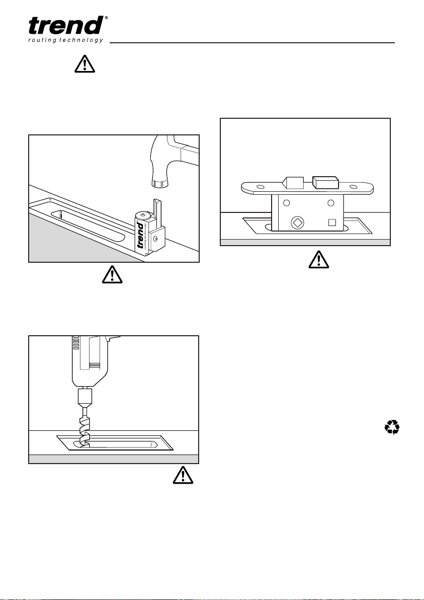
Finishing
■ For square faceplate locks the corners of the
face-plate recess will need squaring off with a
sharp chisel. Alternatively the Trend Corner
Chisel Ref. C/CHISEL, can be used to square
off the rounded corners with one tap of a
hammer.
Deeper Mortise
■ Should you need to cut the mortise deeper
than the maximum depth possible with the
router cutter or router, use a relevant sized
auger bit in an electric drill to complete the
operation.
bolt as far as it will go and gently move the
door backwards and forwards.
■ The pencil marks on the frame will indicate
the position of the recess for the lock striking.
TIP
Before testing fit of the lock, engage the
lock bolt in the locked position to enable
the lock to be removed easily.
MAINTENANCE
Please use only Trend original spare parts and
accessories.
The jig has been designed to operate over
a long period of time with a minimum of
maintenance. Continual satisfactory operation
depends upon proper tool care and regular
cleaning.
Cleaning
■ Regularly clean the jig with a soft cloth.
Lubrication
■ Your jig requires no additional lubrication.
Storage
■ After use, store jig in its packaging.
Cutting Key and Spindle Holes
■ Use a drill fitted with a suitable size drill bit to
bore a hole for the spindle and the keyhole.
■ Insert the lock body, test spindle and key
actions then screw lock into place.
■ To mark the frame to receive the striking
plate, heavily mark the end of the lock bolt
with a pencil. Close the door, open the lock
ENVIRONMENTAL PROTECTION
Recycle raw materials instead of disposing
as waste.
Packaging should be sorted for environmentalfriendly recycling.
The product and its accessories at the end of
their life should be sorted for environmental
friendly recycling.
GUARANTEE
The jig carries a manufacturers guarantee in
accordance with the conditions on the enclosed
guarantee card.
-15--15-
Page 17

LOCK/JIG/A
Please use only Trend original spare parts.
LOCK/JIG/A - SPARE PARTS LIST v2.1 06/2016
No. Qty. Desc. Ref.
1 1 Lock Jig A Body WP-LOCK/A/01
2 1 Clamp Bar for Lock Jig A WP-LOCK/A/02
3 6 Spacer Finger WP-LOCK/03
4 2 Mini Knob 15mm Female M5 x 15mm WP-LOCK/04
5 3 Adjustable Lever Female M8 WP-LOCK/05
6 2 Lobe Knob Male M10 x 40mm Ball End WP-LOCK/06A
7 3 Washer 8.5mm x 25mm x 1.5mm WP-WASH/17
8 2 Plastic Cap Ball End WP-LOCK/08A
9 - - 10 - - 11 2 Spring Washer M5 WP-WASH/29
12 1 Mortise Template A (35mm x 198mm) WP-LOCK/A/T/A
13 1 Face Plate Template 1 (38mm x 253mm) WP-LOCK/A/T/1
1 Face Plate Template 2 (42mm x 253mm) WP-LOCK/A/T/2
14 1 Adaptor Plate for Smaller Templates WP-LOCK/A/14
15 1 Magnet 15mm x 3mm (Pack of 4) MAG/PACK/1
16 1 Guide Bush Collar 16mm to 30mm GB/COLL/1630
17 1 Manual MANU/LOCK/A
-16--16-
Page 18
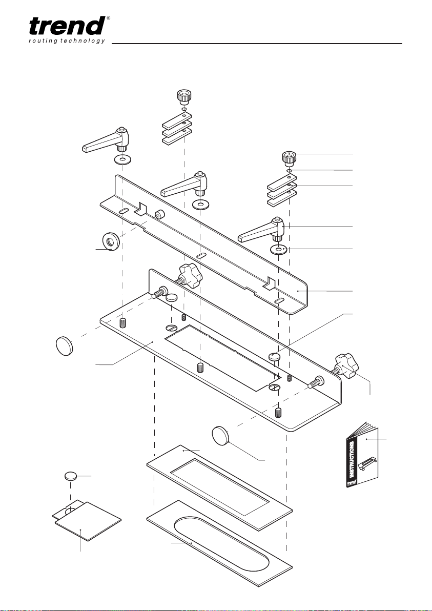
LOCK/JIG/A
16
7
6
5
4
3
2
1
11
8
15
17
12
13
15
14
LOCK JIG A
LOCK/JIG/A - SPARE PARTS DIAGRAM v2.1 06/2016
-IB-
Page 19

Trend Machinery & Cutting Tools Ltd.
Odhams Trading Estate St Albans Road
Watford WD24 7TR England
Tel: 0044(0)1923 249911
MANU/LOCK/A v4.1
© Copyright Trend 2014, 2016. No part of this publication may be reproduced, stored or transmitted in any form without prior
permission. Our policy of continuous improvement means that specifications may change without notice. Trend Machinery and
Cutting Tools cannot be held liable for any material rendered unusable or any form of consequential loss. E&OE
RECYCLABLE
®
All trademarks acknowledged.
[email protected]
www.trend-uk.com
 Loading...