

Page 1
Clip on Current Transducers
Important: Retain these instructions
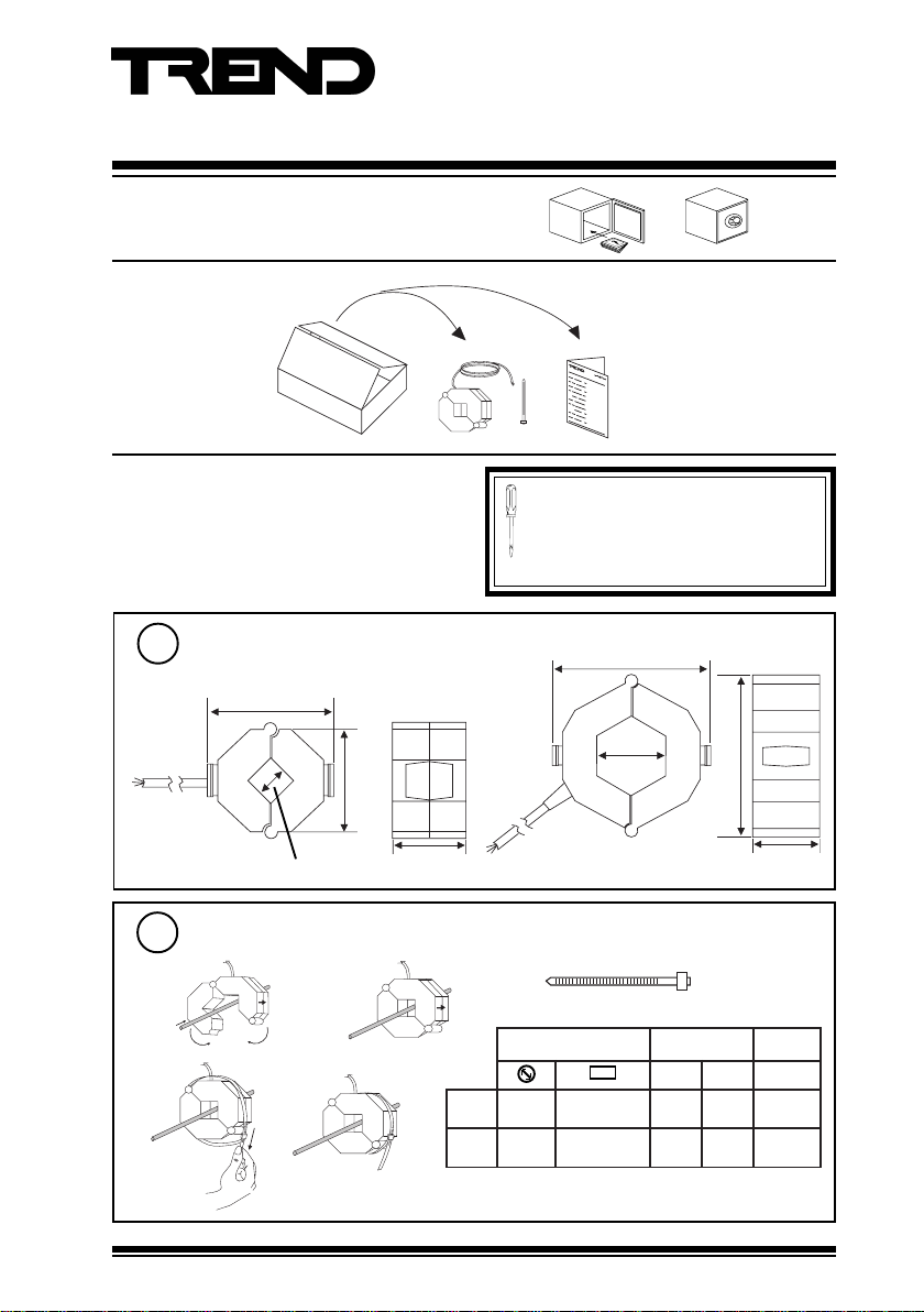
UNPACKING
Installation Instructions
CTX
CTX Installation Instructions
TG200422
INSTALLATION
Dimensions
1
/200
2 m (2 yds)
2
60 mm (2.36”)
Mount CTX on Conductor
a
d
16 mm (0.63”)
b
e
58 mm (2.28”)
36 mm
(1.42”)
It is recommended that the installation should
comply with the HSE Memorandum of
Guidance on Electricity at Work Regulations
1989. For USA install equipment in
accordance with National Electric Code.
/500
76 mm (2.99”)
2 m (2 yds)
32 mm
(1.26”)
83 mm (3.27”)
34 mm
(1.34”)
c
rotcudnoCegnaRspmAspmA
niMxaMdaolrevO
mm61
002/
)"36.0(
mm23
005/
)"62.1(
* The CTX will monitor current from 0 A, but 1% accuracy
is restricted to range from 6 A to top of range.
mm61x61
0*002004
)"36.0x36.0(
mm81x23
0*0050001
)"17.0x
62.1(
CTX Clip on Current Transducers Installation Instructions TG200422 Issue 1/B 13/03/07
1
Page 2
CTX Installation Instructions
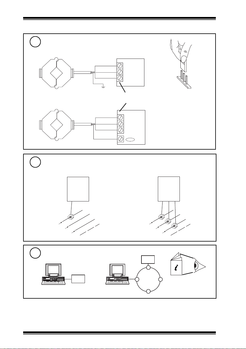
INSTALLATION (continued)
Connect CTX to IQ
3
24 V supply : 24 mA (max)
IQ1xx/2xx
CTX
yellow
black/blue
screen
IN
0 V
red
24 Vdc
Analogue input channel
linked for voltage (V)
V
black/blue
yellow
CTX
For kVA, or kW
4
if balanced load if unbalanced load
IQ
LOAD
N
I Q
5
L1
L2
SUPPLY
L3
Configure IQ
red
screen
or
IQ3
0 (0V)
N (in)
+ (24V)
L1
SUPPLY
I Q
L2
L3
IQ
LOAD
N
IQ Configuration
Manual 90-1533
2
CTX Clip on Current Transducers Installation Instructions TG200422 Issue 1/B 13/03/07
Page 3

Installation Instructions CTX
INSTALLATION (continued)
Set up sensor
6
For IQ controllers link input channel for voltage V and set up the sensor type scaling; the
recommended method of setting the sensor type scaling is to use SET.
For all IQ2 series controllers with firmware of version 2.1 or greater, or IQ3 series controllers,
one of the following SET Unique Sensor References should be used:
CT V 200A (for CTX/200)
CT V 500A (for CTX/500)
Alternatively use sensor scaling mode 5, characterise, and enter the scaling manually as defined
in the table shown.
For all other IQ controllers see the Sensor Scaling Reference Card, TB100521A.
Y epyttupnistloV,0
E tnenopxe3
U reppu002005
L rewol00
P stniop22
X IxxO
1 000
2 01002005
noisreV002/005/
Test
7
IQ
CTX Clip on Current Transducers Installation Instructions TG200422 Issue 1/B 13/03/07
I = xA
3
Page 4

CTX Installation Instructions
DISPOSAL
WEEE Directive :
At the end of their useful life the packaging
and product should be disposed of by a
Do not dispose of with normal household waste.
Do not burn.
suitable recycling centre.
Manufactured for and on behalf of the Environmental and Combustion Controls Division of Honeywell Technologies Sàrl, Ecublens, Route
du Bois 37,Switzerland by its Authorized Representative.
Trend Control Systems Limited reserves the right to revise this publication from time to time and make changes to the content hereof
without obligation to notify any person of such revisions or changes.
Trend Control Systems Limited
P.O. Box 34, Horsham, West Sussex, RH12 2YF, UK. Tel:+44 (0)1403 21888 Fax:+44 (0)1403 241608 www.trend-controls.com
Trend Control Systems USA
6670 185th Avenue NE, Redmond, Washington 98052, USA. Tel: (425)897-3900, Fax: (425)869-8445 www.trend-controls.com
4
CTX Clip on Current Transducers Installation Instructions TG200422 Issue 1/B 13/03/07
 Loading...